9
MOUNTING THE RANGE IN THE OPENING
2
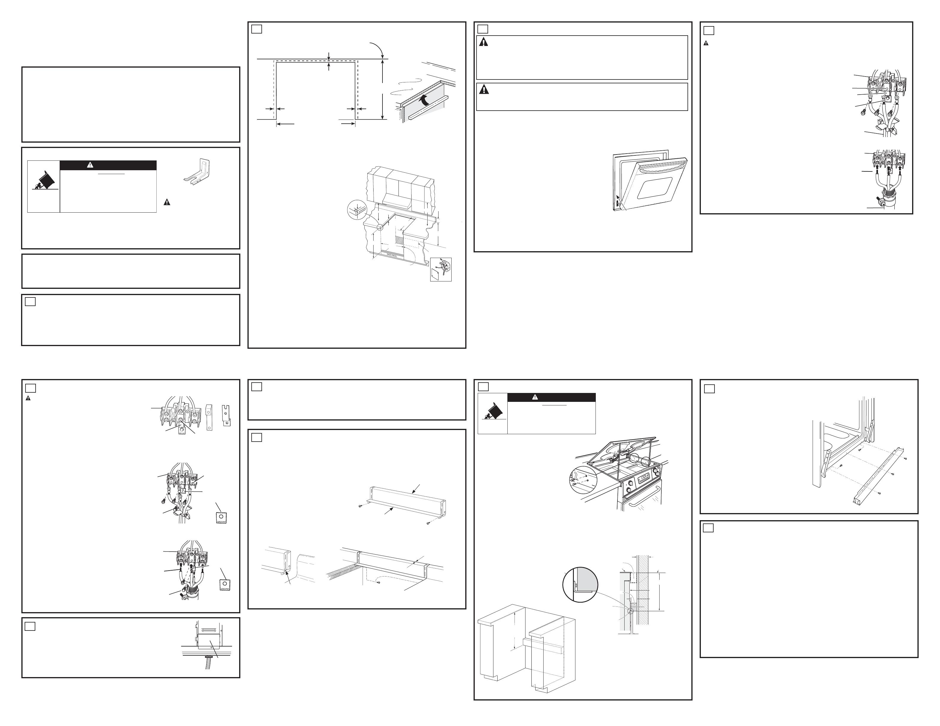
PREPARING THE OPENING (FOR INDOOR USE ONLY)
See the Illustrations for all rough dimensions. The range may be placed with 0” clearance at the side cabinet.
BEFORE YOU BEGIN
Read these instructions completely and
carefully.
•
,03257$17³ Save these instructions
for local inspector’s use.
•
,03257$17³ Observe all governing
codes and ordinances.
• Note to Installer – Be sure to leave these
instructions with Consumer.
• Note to Consumer – Keep these instructions for
future reference.
• Skill level – Installation of this appliance
requires a qualified installer or electrician.
• Proper installation is the responsibility
of the installer.
• Product failure due to improper installation
is not covered under Warranty.
Installation Instructions
27” Drop In Ranges
Questions? Call 1.800.GE.CARES (1.800.432.2737) or visit www.GEAppliances.com
In Canada, call 1.800.561.3344 or visit www.GEAppliances.ca
1
REMOVE PACKAGING MATERIALS
Failure to remove packaging materials could result in damage to the appliance. Remove all packing parts
from oven, racks and heating elements. Remove protective film and labels on the outer door and control
panel. Also, remove plastic on trims and panel and all tape around the oven. Open oven door and remove
literature pack and oven racks. Remove the bottom trim from the side of the oven. It will be installed at
the end of the installation process. The trim is wrapped separately in a plastic bag which also contains
the five screws to secure the bottom trim and the 4 anti-tip screws used to secure the product to the
countertop. The plastic bag is taped to the side of the unit.
ATTENTION INSTALLER: All electric drop-ins must be hard-wired (direct-wired) into an
approved junction box. A plug and receptacle is NOT permitted on these products.
9/16” min.
flat
9/16” min.
flat
26-1/4” smooth cut
Wall
3/8” min. flat
25”
typically
Countertop
Brace
Range support
Countertop thickness 1-1/2” min. is required to support the product. Countertop width 1-1/2” min. is
required to properly support the 3/4” anti-tip screw.
Braces must be installed between the underside of the countertop and the cabinet if required to obtain
1-1/2” minimum thickness (each side)
Make sure the wall coverings, counters and cabinets around the oven can withstand the heat (up to 200°F
[93.3°C]) generated by the oven.
This range is designed to hang from the
counter top. It does not rest on the cabinet.
The range must not be installed on a floor or
sub structure (2” x 4” support)
MATERIALS YOU MAY NEED
Junction Box
Wire Nuts
Strain Relief Clamp for 1/2” Conduit
TOOLS YOU MAY NEED
1/8” Drill Bit and Electric or Hand Drill
Phillips Screwdriver
Wire Strippers
Hand or Saber Saw
•
Allow 30” minimum clearance between sur-
face units and bottom of unprotected wood
or metal cabinet, or allow a 24” minimum
when bottom of wood or metal cabinet is
SURWHFWHGE\QROHVVWKDQµWKLFNÀDPH
retardant millboard covered with not less
than No 28 MSG sheet metal, (.015”), .015”
thick stainless steel, .024” aluminium or
.020” copper.
•
This appliance has been approved for 0”
spacing to adjacent surfaces above the cooktop. However, a 6” minimum spacing to surfaces less than
15” above the cooktop and adjacent cabinet is recommended to reduce exposure to steam, grease splat-
ter and heat.
•
7RUHGXFHWKHULVNRIEXUQVRU¿UHZKHQUHDFKLQJRYHUKRWVXUIDFHHOHPHQWVFDELQHWVWRUDJHVSDFH
above the cooktop should be avoided. If cabinet storage space is to be provided above the cooktop, the
risk can be reduced by installing a range hood that projects at least 5” beyond the front of the cabinets.
Cabinets installed above the cooktop must be no deeper than 16”.
Locate a wiring junction box at the rear of the cutout. The dimension from the top of the wiring junction
ER[WRWKHFRXQWHUWRSPXVWEHDPLQLPXPRIµ7KHER[PXVWQRWH[WHQGPRUHWKDWµRȺWKHSODQH
of a wall. The junction box must be located where it will allow considerable slack in the range conduit, so
that the range can be pulled for servicing if necessary.
9
MOUNTING THE RANGE IN THE OPENING (CONT.)
Bottom Trim Installation
•
Attach the bottom trim to the front frame and side
trim with color matched screws provided in the
hardware bag attached to the side of the unit.
Replace the Oven Door
•
Hold the door over the hinges with the slots at the
bottom edge of the door lined up with the hinges.
The hinge arms must still be in the broil stop posi-
tion.
•
Slide the door down onto the hinges as far as it will
go and close the door
3
ELECTRICAL REQUIREMENTS
WARNING
Electric Shock Hazard
• This appliance must be properly grounded.
• Do not use an extension cord.
%HIRUHLQVWDOOLQJUDQJHVZLWFKSRZHURȺDWWKHVHUYLFHSDQHODQGORFNWKHVHUYLFHGLVFRQQHFWLQJPHDQV
to
prevent power from being switched on accidentally. When the disconnection means cannot be locked,
securely fasten a prominent warning device, such as a tag, to the service panel.
Failure to follow these instructions may result in serious injury or death.
WARNING Fire Hazard
,PSURSHUFRQQHFWLRQRIDOXPLQXPKRXVHZLULQJWRFRSSHUOHDGVFDQUHVXOWLQDQHOHFWULFDORU¿UHKD]DUG,I
residence leads are aluminum, use only connectors designed for joining copper to aluminum and follow the
manufacturer’s recommended procedure closely. Failure to do so may result in serious injury or death.
:HUHFRPPHQG\RXKDYHWKHHOHFWULFDOZLULQJDQGKRRNXSRI\RXUDSSOLDQFHFRQQHFWHGE\DTXDOL¿HGHOHFWULFLDQ
After installation, have the electrician show you how to disconnect power from the appliance.
<RXPXVWXVHDVLQJOHSKDVH9$&RU9$&+HUW]HOHFWULFDOV\VWHP
(ȺHFWLYH-DQXDU\WKH1DWLRQDO(OHF
WULFDO&RGHUHTXLUHVWKDWQHZFRQVWUXFWLRQQRWH[LVWLQJXWLOL]HDIRXU
conductor connection to an electric oven. When installing an electric oven in new construction, a mobile home,
recreational vehicle or an area where local codes prohibit grounding through the neutral conductor, refer to the
section on four-conductor branch circuit connections.
Check with your local utilities for electrical codes which apply in your
area. Failure to wire your oven according to governing codes could
UHVXOWLQDKD]DUGRXVFRQGLWLRQ,IWKHUHDUHQRORFDOFRGHV\RXURYHQ
must be wired and fused to meet the National Electrical Code, NFPA
No. 70 – latest edition, available from the National Fire Protection
Association.
Rating plate is located on oven front frame and is visible when oven
door is open.
This appliance must be supplied with the proper voltage and
frequency, and connected to an individual, properly grounded, 40
amp (minimum) branch circuit protected by a circuit breaker or time-
delay fuse.
'2127VKRUWHQWKHÀH[LEOHFRQGXLW7KHFRQGXLWVWUDLQUHOLHIFODPS
PXVWEHVHFXUHO\DWWDFKHGWRWKHMXQFWLRQER[DQGWKHÀH[LEOHFRQGXLW
PXVWEHVHFXUHO\DWWDFKHGWRWKHFODPS,IWKHÀH[LEOHFRQGXLWZLOOQRW¿W
ZLWKLQWKHFODPSGRQRWLQVWDOOWKHRYHQXQWLODFODPSRIWKHSURSHUVL]HLVREWDLQHG
The 3 power leads supplied with this appliance are suitable for connection to heavier gauge household wiring. The
insulation of these 3 leads is rated for temperatures much higher than the temperature rating of the household
wiring. The current-carrying capacity of the conductor is governed by the wire gauge and the temperature rating of
the insulation around the wire.
Rating Plate Location
Bottom Trim
7
CHECK FOR PROPER INSTALLATION OF ANTI-TIP SCREWS
• Raise lift-up cooktop and support it with cooktop support rod so anti tip screws are visible. (see Section 6)
• Lower the oven door and gently apply a medium force to the inside of the door at the handle end.
• Properly installed screws will prevent any movement of the range when force is applied to the door. If
movement occurs, refer to “Mounting the range in the opening” section.
10
FINAL INSTALLATION CHECKLIST
• Check to make sure the circuit breaker is closed (RESET) or the circuit fuses are replaced.
• Be sure power is in service to the building.
•
Check that all packing material and tape have been removed. Failure to remove these materials could result
in damage to the appliance once the appliance has been turned on and surfaces have heated.
• Remove all items from inside the oven.
&RQ¿UPWKDWDQWLWLSGHYLFHKDVEHHQSURSHUO\LQVWDOOHGVHH6HFWLRQ6).
• Check that the bottom trim is installed properly (see Section 6).
OPERATION CHECKLIST
• Turn on one of the surface units to observe that the element glows within 60 seconds. Turn the unit
RȺZKHQJORZLVGHWHFWHG,IWKHJORZLVQRWGHWHFWHGZLWKLQWKHWLPHOLPLWUHFKHFNWKHUDQJHZLULQJ
connections. If change is required, retest again. If no change is required, have building wiring checked
for proper connections and voltage.
&KHFNWKDWWKH&ORFNGLVSOD\LVHQHUJL]HG,IDVHULHVRIKRUL]RQWDOUHGOLQHVDSSHDULQWKHGLVSOD\
disconnect power immediately. Recheck the range wiring connections. If change is made to
connections, retest again. If no change is required, have building wiring checked for proper connections
and voltage. It is recommended that the clock be changed if the red lines appear.
• Turn on the power to your oven(refer to Owner’s manual). Verify that the bake and broil operate
properly.
• See your owner’s manual for trouble shooting list.
• Be sure all of the oven controls are OFF before leaving the oven.
Do not install
screws here
8
WHEN INSTALLING RANGE IN COUNTERTOP WHICH IS CUT OUT
TO THE WALL
If you have an existing 27” wide cutout that goes all the way to the wall, you may want to buy a
backsplash kit for your range. Order Kit JX27RWH (White) or Kit JX27RBK (Black). This kit will fill in the
space between the back of the range and the wall.
BACKSPLASH KIT FOR 27” DROP-IN RANGES
This kit contains:
1 Backsplash
2 Screws
1 Maintop Filler
2 Wood Screws
NOTE: The backsplash attaches to the counter. The
range slides into position after the backsplash is in
place.
Follow the instructions packed with the backsplach kit.
Backsplash with End Caps
Possible Gap May Occur
Wood Screws Provided
Filler
Screw
Trim for any interference
with postformed backsplash
on countertop.
Both
sides
Install Anti-Tip Screws
• Raise lift-up cooktop and support it
with cooktop support rod.
•
Drill 1/8” diameter pilot holes into
the countertop using holes in upper
side panels. Attach range to the
countertop with four silver screws
provided in the hardware bag taped to
the side of the unit.
NOTE: Screws are (8 - 18 x .75”).
A child or adult can tip the range and be killed.
Install the anti-tip device (screws or bracket) per
instruction below.
Re-engage the anti-tip bracket if the range is moved.
Failure to follow these instructions can result in death or
serious burns to children or adults.
Tip-Over Hazard
WARNING
NOTE: If the countertop is less than
1-1/2” thick, refer to “Preparing the
opening” section.
If countertop screws cannot be used, an anti-tip support must be mounted to rear wall of the cutout.
The anti-tip bracket support is typically a 2x4 piece of wood screwed directly into the wall studs. The
anti-tip bracket support must be able to withstand 200 lbs. of force at the engagement point.
18-3/16”
Countertop
surface
Cover
Anti-tip support
anchored to
wall stud is
required
Anti-tip bracket
Anti-tip
support
Interior wall
Wall stud
Maintop
Anti-tip support to
engage bracket by
1/2” min.
ANTI-TIP INSTALLATION WHEN
COUNTERTOP SCREWS CANNOT BE USED
18-3/16” from
countertop to
anti-tip support
31-10830-2 08-15 GE
FOR YOUR SAFETY:
WARNING
Before beginning
the installation, switch power off at
service panel and lock the service
disconnecting means to prevent power
from being switched on accidentally.
When the service disconnecting means
cannot be locked, securely fasten a
prominent warning device, such as a
tag, to the service panel.
• A child or adult can tip the range and be killed.
• Install the anti-tip bracket to the wall or floor.
• Engage the range to the anti-tip bracket by sliding the
range back such that the foot is engaged.
• Re-engage the anti-tip bracket if the range is moved.
• Failure to do so can result in death or serious burns
to children or adults.
Tip-Over Hazard
WARNING
Anti-Tip Bracket
Kit Included
If you did not receive an anti-tip bracket with your purchase,
call 1.800.626.8774 to receive one at no cost. (In Canada,
call 1.800.561.3344.) For installation instructions of the bracket,
visit: www.GEAppliances.com. (In Canada, www.GEAppliances.ca.)
4
3-WIRE INSTALLATION
WARNING:
The neutral or ground wire of the power cord must be connected to the neutral
terminal located in the center of the terminal block. Ground strap must connect the neutral teminal
to the ground plate. The power leads must be connected to the lower left and the lower right
terminals of the terminal block.
DO NOT remove the ground strap connection.
FOR POWER CORD INSTALLATION
A. Remove the 3 lower terminal screws from the terminal block.
B. Insert the 3 terminal screws through each power cord terminal
ring and into the lower terminals of the terminal block. Be
certain that the center wire (white/neutral) is connected to the
center lower position of the terminal block.
C. Tighten screws securely into the terminal block.
FOR CONDUIT INSTALLATION
A. Loosen the 3 lower terminal screws on the terminal block. Strip
wire to exposed tip about 5/8” long.
B. Insert the center (white/neutral) wire tip through the bottom
center terminal block opening. On certain models, the wire will need to be
inserted through the ground strap opening and then into the bottom
center block opening. Insert the two side bare wire tips into the lower left
and the lower right terminal block openings.
C. 7LJKWHQVFUHZVXQWLOWKHZLUHLV¿UPO\VHFXUHGWRLQFKOEV
Do not over-tighten the screws.
NOTE: ALUMINUM WIRING: Aluminum building wire may
be used but it must be rated for the correct amperage and voltage.
PROCEED TO 5.
Ground
strap
Terminal block
(appearance
may vary)
Neutral
terminal
Power cord
Ground
plate
Power Cord
Wire tips
Terminal
block
Conduit
Conduit
5
4-WIRE INSTALLATION
WARNING: The neutral wire of the
supply circuit must be connected to the neutral
terminal located in the lower center of the terminal
block. The power leads must be connected to the
lower left and the lower
right terminals of the terminal block. The grounding
lead must be connected to the frame of the range
with the ground plate and the green ground screw.
FOR POWER CORD INSTALLATION
A. Remove the 3 lower terminal screws from the terminal
block. Remove the ground screw and
ground plate and retain them. Cut and discard
the ground strap. DO NOT DISCARD ANY SCREWS.
B. Insert the one ground screw into the power cord ground wire
terminal ring, through the ground plate and into
the frame of the range.
C. Insert the 3 terminal screws (removed earlier) through each power
cord terminal ring and into the lower terminals
of the terminal block. Be certain that the center wire (white/neutral)
is connected to the center lower position of the terminal block.
Tighten screws securely into the terminal block.
FOR CONDUIT INSTALLATION
A. Loosen the 3 lower terminal screws on the terminal block.
Strip wire to exposed tip about 5/8” long.
B. Insert the center (white/neutral) wire tip through the
bottom center terminal block opening. On certain models,
the wire will need to be ins erted through the ground
strap opening and then into the bottom center block
opening. Insert the two side bare wire tips into the
lower left and the lower right terminal block openings.
C. 7LJKWHQWKHVFUHZVXQWLOWKHZLUHLV¿UPO\VHFXUHG
(35 to 50 inch-lbs.). Do not over-tighten the screws.
NOTE: ALUMINUM WIRING: Aluminum building wire
may be used but it must be rated
for the correct amperage and voltage.
Before–Power Cord and Conduit
Terminal
block
Terminal
block
Neutral terminal
Neutral
terminal
Ground
strap
Ground plate
(grounding to
range)
Ground
screw
Ground strap
or
After–Conduit
Terminal
block
Ground
plate
(grounding
to range)
Wire
tips
Ground screw
After–Power Cord
18” Min.
4” MAX.
*
TRIM SECTION FOR
COUNTERTOP WITH
POST FORMED OR
RAISED FRONT EDGE
28-7/16”
28-1/2”
MIN.
27”
BETWEEN
CABINETS
MOULDING MAY BE FITTED TO
THE OVEN TRIM FOR A MORE
CUSTOM APPEARANCE
13/32”
30” MIN.
JUNCTION BOX LOCATION
(BOX MUST NOT EXTEND MORE THAN
3” OFF THE PLANE OF THE WALL)
21-3/4” CABINET
FACE TO REAR OF
CUT-OUT
6
REPLACE THE WIRE COVER
Replace wire cover on range back by sliding its left edge under the retaining
tabs and replace the screws removed earlier. Make sure that no wires are pinched
between cover and range back.
Wire
cover
NOTE:
The bottom of the trim provides an
opening for cooling air to enter the cabinet.
)RUSURSHUDLUÀRZWKHRSHQLQJVKRXOGQHYHU
be blocked.


