Page is loading ...

JAPAN
RZ Series
STEREO MICROSCOPES
The MEIJI TECHNO RZ series of advanced, high performance, modular, stereo microscopes are
specifically designed with today’s demanding applications in mind.
Engineered around a Common Main Objective and parallel optical paths, the RZ series offers crisp,
distortion-free, high-resolution images at magnifications ranging from 3.75X to 300X.
Featuring a 10:1 zoom ratio, built-in variable double iris diaphragms, and positive detente click-stops at
12 positions of magnification. Two perpendicular columns of eight zoom lenses in four groups move in a
smooth continuous motion by rotation of the ergonomically sized and positioned zoom control.
A magnification indicator is conveniently located on the zoom control. The RZ series is also coated with
a special anti-static finish, which is especially useful when working with sensitive electronic components.
Ergonomic and standard heads are available. The ergonomic head features low positioned eyetubes
and is adjustable vertically from 10 to 50 for comfortable, fatigue-free viewing. Interpupillary distance
is adjustable from 52mm to 75mm. The standard, economical binocular head is inclined at 45 with an
interpupillary adjustment ranging from 46mm to 75mm.
Distortion-free, ultra wide-field eyepieces with dioptric adjustment are available in several powers of
magnification and are provided with reticule mounts for measurement and photomicrography.
A coaxial coarse and fine focus mechanism with a 50mm focusing range is provided for ultra-smooth and
precise focus control.
MEIJI TECHNO’s RZ series offers a full range of optional modular accessories including: Ergonomic
Binocular Body, Coaxial Vertical Illuminator, TV Camera Adapter, Varied Interchangeable Objectives and
Widefield Eyepieces, Polarizing Filters, Brightfield Transmitted Light Stand, Brightfield/Darkfield
Transmitted Light Base, Photomicrographic Systems and various other components and accessories for
complete system versatility.
3

Page
INSTRUCTION
................................................................................................................
3
ASSEMBLY INSTRUCTIONS
.........................................................................................
4
USE
Installing the Eye Guards
...........................................................................................
6
Installing the Eyepieces
..............................................................................................
6
Adjusting the Interpupillary Distance
..........................................................................
6
Determining the Correct Eyepoint
..............................................................................
6
Eyeglass Wearers
......................................................................................................
6
Standard Binocular Head
...........................................................................................
7
Ergonomic Binocular Head
.........................................................................................
7
Adjusting the Viewing Height
......................................................................................
7
Adjusting for Specimen Height
...................................................................................
7
Focus Controls
...........................................................................................................
7
Tension Controls
........................................................................................................
8
Changing the Magnification
........................................................................................
8
Magnification Index
.....................................................................................................
8
Dioptric and Parfocality Adjustment
............................................................................
8
Dioptric and Parfocality Adjustment with Eyepiece Reticle
........................................
9
Double Iris Diaphragm
................................................................................................
9
Coaxial Vertical Illuminator
.........................................................................................
9
STANDS
RZP Plain Stand
.......................................................................................................
10
RZT Transmitted Light Stand
...................................................................................
11
RZDT Brightfield/Darkfield Transmitted Light Stand
.................................................
11
RZBD Brightfield/Darkfield Transmitted Light Stand
................................................
12
MAC Universal Boom Stand
.....................................................................................
12
ILLUMINATORS
COX Coaxial Vertical Illuminator
..............................................................................
14
Oblique Illumination
..................................................................................................
10
Annular Illumination
..................................................................................................
10
Fluorescent Ring Illumination
...................................................................................
10
STAGES
Graduated Mechanical Stage for RZP
......................................................................
13
Graduated Mechanical Stage for RZT, RZDT, RZBD
..............................................
13
Ungraduated Mechanical Stage for RZP
..................................................................
13
Ungraduated Mechanical Stage for RZT, RZDT, RZBD
...........................................
13
Polarizing Stage for RZT, RZDT, RZBD
...................................................................
13
PHOTOMICROSCOPY AND VIDEOMICROSCOPY PARTS AND ACCESSORIES
MA751 Photo/Video Attachment
..............................................................................
15
MA752 Auxiliary Video Attachment
..........................................................................
16
35mm Photomicroscopy Equipment
.........................................................................
17
Installing MA150/50 and MA150/60 Camera Attachment
........................................
18
Using the MA150/50 and MA150/60 Camera Attachment
..................................
19-20
Large Format Photomicroscopy Equipment
.............................................................
21
Using the Framing Reticle
........................................................................................
22
Installing MA752 Auxiliary Video Attachment “C” Mounts
........................................
24
Installing MA751 Photo/Video Attachment “C” Mounts
............................................
25
MA765 Drawing Attachment
.....................................................................................
25
OPTICAL DATA
............................................................................................................
26
MAINTENANCE AND CARE
........................................................................................
27
Replacing the Bulb or Fuse
......................................................................................
27
Bulb Replacement RZT Stand
..................................................................................
27
Bulb Replacement RZDT Stand
...............................................................................
27
Bulb Replacement RZBD Stand
...............................................................................
28
Care
..........................................................................................................................
28
Cleaning
...................................................................................................................
28

JAPAN
RZ Series
STEREO MICROSCOPES
The MEIJI TECHNO RZ series of advanced, high performance, modular, stereo microscopes are
specifically designed with today’s demanding applications in mind.
Engineered around a Common Main Objective and parallel optical paths, the RZ series offers crisp,
distortion-free, high-resolution images at magnifications ranging from 3.75X to 300X.
Featuring a 10:1 zoom ratio, built-in variable double iris diaphragms, and positive detente click-stops at
12 positions of magnification. Two perpendicular columns of eight zoom lenses in four groups move in a
smooth continuous motion by rotation of the ergonomically sized and positioned zoom control.
A magnification indicator is conveniently located on the zoom control. The RZ series is also coated with
a special anti-static finish, which is especially useful when working with sensitive electronic components.
Ergonomic and standard heads are available. The ergonomic head features low positioned eyetubes
and is adjustable vertically from 10 to 50 for comfortable, fatigue-free viewing. Interpupillary distance
is adjustable from 52mm to 75mm. The standard, economical binocular head is inclined at 45 with an
interpupillary adjustment ranging from 46mm to 75mm.
Distortion-free, ultra wide-field eyepieces with dioptric adjustment are available in several powers of
magnification and are provided with reticule mounts for measurement and photomicrography.
A coaxial coarse and fine focus mechanism with a 50mm focusing range is provided for ultra-smooth and
precise focus control.
MEIJI TECHNO’s RZ series offers a full range of optional modular accessories including: Ergonomic
Binocular Body, Coaxial Vertical Illuminator, TV Camera Adapter, Varied Interchangeable Objectives and
Widefield Eyepieces, Polarizing Filters, Brightfield Transmitted Light Stand, Brightfield/Darkfield
Transmitted Light Base, Photomicrographic Systems and various other components and accessories for
complete system versatility.
3

4
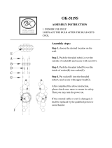
ASSEMBLY INSTRUCTIONS
Read these instructions thoroughly before attempting assembly. The RZ is a modular system, and your
configuration might not include all of the parts discussed in this manual. This will affect the assembly
process, so be sure that you understand how your components fit together and the order in which they
should be assembled before you begin. Make sure that all exposed lens and prism surfaces on each
part are clean and free of dust before assembly.
(1) Unpacking: Carefully remove each part from its shipping container, and verify that you have received
all items on the packing list. It is a good idea to keep the packaging material, as it is useful for future
storage or transport.
(2) Microscope Body and Stand: The microscope body may already be mounted on the stand. If not,
loosen the set screw at the back of the body and slide the body over the vertical mounting post on the
stand. Make sure that both the body set screw and the safety collar set screw are well tightened. To
protect the microscope body from damage, remember to adjust the safety collar each time you raise
or lower the body.
(3) Objective: Screw the objective lens into the threaded opening on the bottom of the microscope body.
Be careful not to drop the objective or touch the exposed lens surfaces.
Body
Objective
Mounting Post
Set Screw
Safety Collar
Stand
STANDARD BINOCULAR HEAD
The standard binocular head is inclined at 45 degree. The interpupillary
distance is adjustable from 46mm to 75mm.
ERGONOMIC BINOCULAR HEAD
The ergonomic binocular head viewing angle is adjustable from 10 to 50 and
the interpupillary distance is adjustable from 52mm to 75mm.
ADJUSTING THE VIEWING HEIGHT
The viewing height is correctly adjusted when your body, neck and back are
positioned to avoid fatigue and strain. In the case of the ergonomic head the
viewing angle (10
50 ) can be adjusted by holding the eyepiece tubes and
swinging them upwards or downwards.
When using the standard viewing head the eyetubes are fixed and the viewing
height can only be adjusted by increasing or decreasing the height of your
worktable or chair.
ADJUSTING FOR SPECIMEN HEIGHT
Set the diopter adjustments to zero. Place a specimen beneath the
microscope objective. Zoom to the lowest end of the zoom range (7.5).
Loosen the clamp screw holding the microscope body on the stand while
supporting the weight of the body with your free hand. Raise and lower the
body while looking through the eyepieces until the image is roughly in focus.
Tighten the clamp screw.
FOCUS CONTROLS
The coaxial coarse and fine focus controls are located on each side of the
microscope body and can be operated from either side of the microscope.
The coarse focus control rotates a full 360 and allows the microscope to
travel vertically over a distance of 50mm or 2 inches.
7

(4) Viewing Head: A basic RZ system will have the viewing head mounted directly to the microscope
body. However, If your system includes the COX Coaxial Illuminator or the MA751 Photo/Video
Attachment, these items must be installed before the head is mounted (see Page15 ). The dovetail
on the bottom of the viewing head (ergonomic or standard) fits into the mount on the top of the
microscope body. Loosen the set screw on the upper front of the body, and place the viewing head
into the mount. The guide pin at the back of the mount should fit into the slot at the rear of the
dovetail. Re-tighten the set screw to hold the head firmly in place.
(5) Eyepieces: Loosen the set screws on the eyepieces and slide them over the eyetubes on the viewing
head until they are fully seated. Orient the set screws downwards, tighten them, and set the diopter
adjustment rings on both eyepieces to zero (see diagram).
5
Dovetail
Eyetube
Viewing Head
Set Screw
Diopter Adjustment
Mount
Guide Pin
Set Screw
Eyepieces
6
INSTALLING THE EYE GUARDS
Each eyepiece is provided with a protective rubber eye guard. Use of the
rubber eye guard protects the optical surface of the eyepiece from accidental
damage and prevents stray light from interfering with the image you are
viewing. The protective eye guard simply slips over the viewing end of each
eyepiece until it is firmly seated.
INSTALLING THE EYEPIECES
Loosen the set screws on the eyepieces and insert them into the eyetubes on
the viewing head until they are fully seated. Orient the set screws downwards,
tighten them, and set the diopter adjustment rings on both eyepieces to zero.
The dioptric range is from
5 to 5.
ADJUSTING THE INTERPUPILLARY DISTANCE
The correct interpupillary distance is achieved when the viewer observes a
single circular field of view when using both eyes to view a specimen. The
interpupillary distance is set by moving the eyetubes closer together or farther
apart. The interpupillary distance will vary from individual to individual.
Interpupillary distance range: Standard head 46mm
75mm, Ergonomic head
52mm 75mm.
DETERMINING THE CORRECT EYEPOINT
The eyepoint of the eyepiece is the distance from the eyepiece to the pupil of
the eye. To find the eyepoint or correct viewing position move your eyes closer
to the eyepiece until the image of the specimen and the entire field of view is
observed without restriction.
EYEGLASS WEARERS
If you are an eyeglass wearer and the rubber eye guards interfere with viewing
of the specimen then fold the eye guards back upon themselves to give you
more distance between the eyepiece and your eyeglasses.

4
ASSEMBLY INSTRUCTIONS
Read these instructions thoroughly before attempting assembly. The RZ is a modular system, and your
configuration might not include all of the parts discussed in this manual. This will affect the assembly
process, so be sure that you understand how your components fit together and the order in which they
should be assembled before you begin. Make sure that all exposed lens and prism surfaces on each
part are clean and free of dust before assembly.
(1) Unpacking: Carefully remove each part from its shipping container, and verify that you have received
all items on the packing list. It is a good idea to keep the packaging material, as it is useful for future
storage or transport.
(2) Microscope Body and Stand: The microscope body may already be mounted on the stand. If not,
loosen the set screw at the back of the body and slide the body over the vertical mounting post on the
stand. Make sure that both the body set screw and the safety collar set screw are well tightened. To
protect the microscope body from damage, remember to adjust the safety collar each time you raise
or lower the body.
(3) Objective: Screw the objective lens into the threaded opening on the bottom of the microscope body.
Be careful not to drop the objective or touch the exposed lens surfaces.
Body
Objective
Mounting Post
Set Screw
Safety Collar
Stand
STANDARD BINOCULAR HEAD
The standard binocular head is inclined at 45 degree. The interpupillary
distance is adjustable from 46mm to 75mm.
ERGONOMIC BINOCULAR HEAD
The ergonomic binocular head viewing angle is adjustable from 10 to 50 and
the interpupillary distance is adjustable from 52mm to 75mm.
ADJUSTING THE VIEWING HEIGHT
The viewing height is correctly adjusted when your body, neck and back are
positioned to avoid fatigue and strain. In the case of the ergonomic head the
viewing angle (10
50 ) can be adjusted by holding the eyepiece tubes and
swinging them upwards or downwards.
When using the standard viewing head the eyetubes are fixed and the viewing
height can only be adjusted by increasing or decreasing the height of your
worktable or chair.
ADJUSTING FOR SPECIMEN HEIGHT
Set the diopter adjustments to zero. Place a specimen beneath the
microscope objective. Zoom to the lowest end of the zoom range (7.5).
Loosen the clamp screw holding the microscope body on the stand while
supporting the weight of the body with your free hand. Raise and lower the
body while looking through the eyepieces until the image is roughly in focus.
Tighten the clamp screw.
FOCUS CONTROLS
The coaxial coarse and fine focus controls are located on each side of the
microscope body and can be operated from either side of the microscope.
The coarse focus control rotates a full 360 and allows the microscope to
travel vertically over a distance of 50mm or 2 inches.
7

8
TENSION CONTROL
The tension control adjustment is located on the left side of the microscope
body directly behind the coaxial coarse focus control. Rotating the tension
control ring clockwise decreases the tension on the focus control mechanism.
Rotating the tension control ring counter-clockwise increases the tension on
the focus control mechanism. The tension control can be set to the user’s
preference.
CHANGING THE MAGNIFICATION
The RZ series microscopes have a continuous zoom range with a 10:1 zoom
ratio and positive detente click stops at twelve positions of magnification. The
zoom controls are located on each side of the microscope and can be
operated from either side of the microscope. Rotate the controls clockwise to
increase the magnification and counter-clockwise to decrease the
magnification.
MAGNIFICATION INDEX
The magnification index shows the actual magnification to the viewer when the
standard 1.0X objective and 10X eyepiece are used. Please refer to the
optical data table on Page 26 to determine the total magnification for various
optional eyepiece/objective combinations.
DIOPTRIC AND PARFOCALITY ADJUSTMENT
Set the dioptric adjustment rings on both eyetubes to zero. Place a flat
specimen on the microscope stage beneath the objective. Zoom the
microscope to the highest end of the zoom range. Focus on the specimen
using the coarse and fine focus controls. Zoom the microscope to the lowest
end of the zoom range. Close your left eye and look into the right eyepiece
with your right eye. Slowly rotate the diopter adjustment ring
or until the
image is sharply focused. Close your right eye and look into the left eyepiece
with your left eye. Slowly rotate the diopter adjustment ring
or until the
image is sharply focused. Zoom the microscope from the low to high position
while viewing the flat specimen. The image should remain in focus throughout
the entire zoom range.
RZT TRANSMITTED LIGHT STAND
The RZT Transmitted Light Stands are used for brightfield observation of
transparent specimens. The RZT features a 6V 30W halogen lamp with
variable intensity control, 95mm diameter clear glass stage plate, two stage
clips and an anti-static finish. A second transformer is incorporated into the
base for use with the optional COX illuminator or auxiliary light source.
Base Dimensions: 280mm wide x 255mm deep x 85mm high
Pillar Height: 325mm
Model No. RZT/100 (110 Volt), RZT/200 (220/240 Volt)
Replacement Bulb: Cat. No. MA326
RZDT BRIGHTFIELD/DARKFIELD TRANSMITTED LIGHT
STAND
The RZDT Transmitted Light Stands are used for brightfield/darkfield
observation of transparent specimens. The RZDT features a 12V 30W
halogen lamp with variable intensity control, 95mm diameter clear glass stage
plate, two stage clips and an anti-static finish. Quick change over from
brightfield to darkfield observation is facilitated by easy to reach, front-
mounted controls. A second transformer is incorporated into the base for use
with the optional COX illuminator or auxiliary light source.
Base Dimensions: 280mm wide x 255mm deep x 85mm high
Pillar Height: 325mm
Model No.RZDT/100 (110 Volt), RZDT/200 (220/240 Volt)
Replacement Bulb: Cat. No. MA275/05
11

DIOPTRIC AND PARFOCALITY ADJUSTMENT
WITH EYEPIECE RETICLE
Install the eyepiece containing the reticle into the right eyetube. Focus the
right eyepiece on the image of the reticle by rotating the dioptric adjustment
rings
or until the image of the reticle is sharply in focus. Place a flat
specimen on the microscope stage beneath the objective. Zoom the
microscope to the highest end of the zoom range (75). Focus on the
specimen using the coarse and fine focus controls. Zoom the microscope to
the lowest end of the zoom range (7.5). Close your right eye and look into the
left eyepiece with your left eye. Slowly rotate the diopter adjustment ring
or
until the image of the specimen is sharply focused. Zoom the microscope
from the low to high position while viewing the flat specimen. The image of the
eyepiece micrometer should remain in focus throughout the extended zoom
range. The image of the specimen will not remain in focus throughout the
extended zoom range. Refocus on the specimen using the coaxial coarse and
fine focus controls.
DOUBLE IRIS DIAPHRAGM
The double iris diaphragm control is located on the front of the microscope
body. Closing down the iris diaphragm enhance contrast and increases the
depth of focus. When the double iris diaphragm is closed down the image
brightness is decreased slightly and exposure times for photographs are
increased. When the double iris diaphragm is closed down the resolution is
also slightly reduced.
COAXIAL VERTICAL ILLUMINATOR
The coaxial vertical illuminator is used when observing flat, highly reflective
specimens such as integrated circuits, semiconductor wafers, polished metal
specimens, solder balls or magnetic recording heads. The coaxial vertical
illuminator fits between the binocular head and the main body of the
microscope and may be used in conjunction with photo/video attachment. A
quarter wave plate is required when using the coaxial vertical illuminator to
view reflective specimens. The quarter wave plate is attached to the bottom of
the objective and is rotated to achieve the desired effect. Use of the coaxial
illuminator increases the total magnification to the viewer by a factor of 1.5X.
Optional optical filters are available and are listed in the COX illuminator
section of this manual. The light source for the coaxial vertical illuminator is a
6V, 30W halogen bulb.
9
10
OBLIQUE ILLUMINATION
Dual-arm fiber optic illumination system is available for oblique illumination.
Composed of a 150W halogen light source, self-supporting, dual-arm fiber
light guides, adapter and focusing lenses.
Cat. No. FL181 (110V), FL181/220 (220/240V)
Replacement Bulb: Cat. No. FL180/70
ANNULAR ILLUMINATION
An annular fiber optic light system is also available for the RZ series stereo
microscopes. Composed of a 150W halogen light source and annular light
guide.
Cat. No. FL182 (110V), FL182/220 (220/240V)
Replacement Bulb: Cat. No. FL180/70
FLUORESCENT RING ILLUMINATION
The MA305/100 (110V) or MA305/200 (220/240V) Fluorescent Ring
Illuminators provide cool, white, diffuse illumination similar to daylight.
Suitable for low magnification examination of delicate organisms that are
sensitive to heat, or for specimens subject to surface reflection. The MA308
adapter is necessary to attach the MA305 illuminator to the RZ series
microscope.
Illuminator: Cat. No. MA305/100 or MA305/200
Adapter: Cat. No. MA308
Replacement Bulb: Cat. No. MA305/05
RZP PLAIN STAND
The RZP Plain Stand consists of an anti-static finished aluminum alloy base
with a 95mm diameter black and white plastic stage plate and two stage clips.
Base Dimensions: 280mm wide x 255mm deep x 35mm high
Pillar Height: 325mm

8
TENSION CONTROL
The tension control adjustment is located on the left side of the microscope
body directly behind the coaxial coarse focus control. Rotating the tension
control ring clockwise decreases the tension on the focus control mechanism.
Rotating the tension control ring counter-clockwise increases the tension on
the focus control mechanism. The tension control can be set to the user’s
preference.
CHANGING THE MAGNIFICATION
The RZ series microscopes have a continuous zoom range with a 10:1 zoom
ratio and positive detente click stops at twelve positions of magnification. The
zoom controls are located on each side of the microscope and can be
operated from either side of the microscope. Rotate the controls clockwise to
increase the magnification and counter-clockwise to decrease the
magnification.
MAGNIFICATION INDEX
The magnification index shows the actual magnification to the viewer when the
standard 1.0X objective and 10X eyepiece are used. Please refer to the
optical data table on Page 26 to determine the total magnification for various
optional eyepiece/objective combinations.
DIOPTRIC AND PARFOCALITY ADJUSTMENT
Set the dioptric adjustment rings on both eyetubes to zero. Place a flat
specimen on the microscope stage beneath the objective. Zoom the
microscope to the highest end of the zoom range. Focus on the specimen
using the coarse and fine focus controls. Zoom the microscope to the lowest
end of the zoom range. Close your left eye and look into the right eyepiece
with your right eye. Slowly rotate the diopter adjustment ring
or until the
image is sharply focused. Close your right eye and look into the left eyepiece
with your left eye. Slowly rotate the diopter adjustment ring
or until the
image is sharply focused. Zoom the microscope from the low to high position
while viewing the flat specimen. The image should remain in focus throughout
the entire zoom range.
RZT TRANSMITTED LIGHT STAND
The RZT Transmitted Light Stands are used for brightfield observation of
transparent specimens. The RZT features a 6V 30W halogen lamp with
variable intensity control, 95mm diameter clear glass stage plate, two stage
clips and an anti-static finish. A second transformer is incorporated into the
base for use with the optional COX illuminator or auxiliary light source.
Base Dimensions: 280mm wide x 255mm deep x 85mm high
Pillar Height: 325mm
Model No. RZT/100 (110 Volt), RZT/200 (220/240 Volt)
Replacement Bulb: Cat. No. MA326
RZDT BRIGHTFIELD/DARKFIELD TRANSMITTED LIGHT
STAND
The RZDT Transmitted Light Stands are used for brightfield/darkfield
observation of transparent specimens. The RZDT features a 12V 30W
halogen lamp with variable intensity control, 95mm diameter clear glass stage
plate, two stage clips and an anti-static finish. Quick change over from
brightfield to darkfield observation is facilitated by easy to reach, front-
mounted controls. A second transformer is incorporated into the base for use
with the optional COX illuminator or auxiliary light source.
Base Dimensions: 280mm wide x 255mm deep x 85mm high
Pillar Height: 325mm
Model No.RZDT/100 (110 Volt), RZDT/200 (220/240 Volt)
Replacement Bulb: Cat. No. MA275/05
11

12
RZBD BRIGHTFIELD/DARKFIELD TRANSMITTED LIGHT
STAND
The RZBD transmitted light stand is used for brightfield/darkfield observation
of transparent specimens. The RZBD stand incorporates an annular optic light
guide and an external 150W halogen light source.
The RZBD stand features an anti-static paint-coated aluminum alloy base
which includes a 95mm diameter clear glass stage plate, two stage clips and a
built-in brightfield/darkfield baffle. Quick change over from brightfield to
darkfield observation is facilitated by easy-to-reach front mounted controls.
Base Dimensions: 280mm wide x 255mm deep x 85mm high
Pillar Height : 325mm
Light source Dimensions: 150mm wide x 230mm deep x 130mm high
Model No. RZBD/100 (110 volt), RZBD/200 (220/240 Volt)
Replacement Bulb : Cat. No. FL180/70
MAC UNIVERSAL STANDS
Universal boom stand for special applications involving large specimens.
Features a 506mm vertical post with hand-operated crank for easy vertical
positioning. The 460mm horizontal articulated arm with lockable joints allows
the RZ to be swung easily into position. Available in three versions:
MAC-1: Without mounting post
MAC-2: With fixed vertical mounting post
MAC-3: With tilting mounting post
Base Dimensions: 305mm x 305mm x 38mm
Pillar Height: 483mm
Swing Arm: 445mm from column center to drop post center
Weight: 38.7kg
PHOTOMICROSCOPY AND VIDEOMICROSCOPY
PARTS AND ACCESSORIES
The primary component necessary for photo or video work with the RZ stereo microscope is the MA751
Photo/Video Attachment. The MA751 allows you to take 35mm or large-format Polaroid photographs
of your specimens, or to display your specimens on a video monitor. If you wish to photograph
specimens while simultaneously displaying them on a video monitor, you can do so by attaching the
MA752 Auxiliary Video Attachment to the MA751 photo/video attachment. (Note: You must have an
MA751 to use the MA752.)
MA751 PHOTO/VIDEO ATTACHMENT
The MA751 Photo/Video Attachment contains a beam-splitter prism which redirects 80% of the light
that would normally go to the eyepieces into the vertical photo tube behind the viewing head. This is
accomplished by means of the beam-splitter slider control on the right side of the photo/video attachment
below the viewing head (marked “BI/PHOTO” and “BI” ). With the slider control in the “BI” position, the
microscope functions normally with 100% of the light directed through the eyepieces. With the slider
control in the “BI/PHOTO” position, the beam-splitter prism redirects 80% of the light through the photo
tube (and auxiliary video attachment, if installed) and 20% through the eyepieces. This allows you to
view the specimen through the eyepieces while also taking photographs and/or displaying the image on
a video monitor. (Further accessories are needed to attach 35mm or video cameras to the MA751; see
below)
INSTALLATION:
The photo/video attachment uses the same dovetail/guide pin/set screw mount as the viewing head and
coaxial illuminator, so follow the mounting procedure described on Page 5 and 15 to mount the MA751 to
the RZ body. Then mount the viewing head to the MA751 in the same manner. If you are also using the
COX coaxial illuminator, it must be mounted on the RZ body first. The MA751 then mounts to the top of
the COX, and the viewing head to the top of the MA751.
15
Beam-Splitter
Slider Control
Assembly Units
with COX Coaxial Illuminator
COX
MA751
Photo/Video Attachment

GRADUATED MECHANICAL STAGE FOR RZP
This stage has 0.1mm graduations and coaxial controls for precise control of
mounted specimens. Features 116mm x 137mm work surface with stage
clips, 50mm x 75mm X-Y travel.
Cat. No. MA578
GRADUATED MECHANICAL STAGE FOR RZT,
RZBD, RZDT
This stage has 0.1mm graduations and coaxial controls for precise control of
mounted specimens. Features 116mm x 137mm work surface with stage clips
and 74mm x 96mm clear glass plate for use with transmitted light stands,
50mm x 75mm X-Y travel.
Cat. No. MA578/05
UNGRADUATED SLIDING MECHANICAL STAGE
FOR RZP
This stage features a 125mm x 170mm work surface with stage clips. Roller
bearing mount allows smooth, easy, fingertip control over 100mm x 100mm X-
Y travel.
Cat. No. MA565
UNGRADUATED SLIDING MECHANICAL STAGE
FOR RZT, RZBD, RZDT
This stage features a 125mm x 170mm work surface with stage clips and a
94.5mm diameter clear glass plate for use with transmitted light stands. Roller
bearing mount allows smooth, easy, fingertip control over 100mm x 100mm X-
Y travel.
Cat. No. MA565/05
POLARIZING STAGE (fits RZT, RZBD and RZDT)
150mm diameter rotatable stage with 1 vernier markings and detent.
Includes 1st order red and quarter wave plates in sliding mounts, and stage
clips.
Cat. No. MA761
13
14
COX COAXIAL ILLUMINATOR
The COX Coaxial Illuminator directs light from a 6V 30W halogen lamp (replacement bulb: MA326)
down through the objective lens onto your specimen and increases the microscope magnification by a
factor of 1.5X. This vertical lighting is especially useful for viewing highly reflective surfaces such as
solder balls, integrated circuits, wafers, or magnetic recording heads, as well as for illuminating small pits
and other surfaces that would otherwise be in shadow. The MA762 quarter wave plate (ordered
separately) is required for use with the COX to reduce glare and reflection. The COX also has dual filter
slots that accepts these five optional filters:
MA754 LB100 clear blue
MA755 G533 clear green
MA756 Y48 clear yellow
MA757 ND2 neutral density
MA758 ND8 neutral density
If you have a transmitted light stage (RZT, RZBD, RZDT) the COX draws power from a socket at the rear
of the base. If you do not have one of these stands, you will need the MA651/05 (115V) or the
MA651/10 (220V) power supply to provide 6V 30W current to the COX.
INSTALLATION:
The COX mounts directly to the RZ body below the viewing head using the same dovetail/guide pin/slot
mount as the viewing head. If the head is already installed, remove it. Loosen the set screw on the
upper front of the body, and place the dovetail on the bottom of the COX into the mount. The guide pin at
the back of the mount should fit into the slot at the rear of the dovetail. Re-tighten the set screw to hold
the COX firmly in place. If your system includes an MA751 photo/video attachment, it should be
mounted in the same manner to the top of the COX (see Page15 ). If not, mount the viewing head to the
top of the COX. Finally, connect the COX plug to the socket either at the rear of the base or at the rear of
the additional power supply.
Filter
Filter Slot
Guide Pin
Mount
Set Screw
Coaxial Illuminator
Dovetail
Power Supply
Quarter Wave Plate

12
RZBD BRIGHTFIELD/DARKFIELD TRANSMITTED LIGHT
STAND
The RZBD transmitted light stand is used for brightfield/darkfield observation
of transparent specimens. The RZBD stand incorporates an annular optic light
guide and an external 150W halogen light source.
The RZBD stand features an anti-static paint-coated aluminum alloy base
which includes a 95mm diameter clear glass stage plate, two stage clips and a
built-in brightfield/darkfield baffle. Quick change over from brightfield to
darkfield observation is facilitated by easy-to-reach front mounted controls.
Base Dimensions: 280mm wide x 255mm deep x 85mm high
Pillar Height : 325mm
Light source Dimensions: 150mm wide x 230mm deep x 130mm high
Model No. RZBD/100 (110 volt), RZBD/200 (220/240 Volt)
Replacement Bulb : Cat. No. FL180/70
MAC UNIVERSAL STANDS
Universal boom stand for special applications involving large specimens.
Features a 506mm vertical post with hand-operated crank for easy vertical
positioning. The 460mm horizontal articulated arm with lockable joints allows
the RZ to be swung easily into position. Available in three versions:
MAC-1: Without mounting post
MAC-2: With fixed vertical mounting post
MAC-3: With tilting mounting post
Base Dimensions: 305mm x 305mm x 38mm
Pillar Height: 483mm
Swing Arm: 445mm from column center to drop post center
Weight: 38.7kg
PHOTOMICROSCOPY AND VIDEOMICROSCOPY
PARTS AND ACCESSORIES
The primary component necessary for photo or video work with the RZ stereo microscope is the MA751
Photo/Video Attachment. The MA751 allows you to take 35mm or large-format Polaroid photographs
of your specimens, or to display your specimens on a video monitor. If you wish to photograph
specimens while simultaneously displaying them on a video monitor, you can do so by attaching the
MA752 Auxiliary Video Attachment to the MA751 photo/video attachment. (Note: You must have an
MA751 to use the MA752.)
MA751 PHOTO/VIDEO ATTACHMENT
The MA751 Photo/Video Attachment contains a beam-splitter prism which redirects 80% of the light
that would normally go to the eyepieces into the vertical photo tube behind the viewing head. This is
accomplished by means of the beam-splitter slider control on the right side of the photo/video attachment
below the viewing head (marked “BI/PHOTO” and “BI” ). With the slider control in the “BI” position, the
microscope functions normally with 100% of the light directed through the eyepieces. With the slider
control in the “BI/PHOTO” position, the beam-splitter prism redirects 80% of the light through the photo
tube (and auxiliary video attachment, if installed) and 20% through the eyepieces. This allows you to
view the specimen through the eyepieces while also taking photographs and/or displaying the image on
a video monitor. (Further accessories are needed to attach 35mm or video cameras to the MA751; see
below)
INSTALLATION:
The photo/video attachment uses the same dovetail/guide pin/set screw mount as the viewing head and
coaxial illuminator, so follow the mounting procedure described on Page 5 and 15 to mount the MA751 to
the RZ body. Then mount the viewing head to the MA751 in the same manner. If you are also using the
COX coaxial illuminator, it must be mounted on the RZ body first. The MA751 then mounts to the top of
the COX, and the viewing head to the top of the MA751.
15
Beam-Splitter
Slider Control
Assembly Units
with COX Coaxial Illuminator
COX
MA751
Photo/Video Attachment

16
MA752 AUXILIARY VIDEO ATTACHMENT
The MA752 Auxiliary Video Attachment attaches to on the left side of the MA751 photo/video attachment
and allows you to mount an additional video camera to the microscope. A standard “C” mount
(MA151/10) for attaching a video camera is included in the MA752, so if you have a camera and monitor,
no further accessories are required. (Optional “C” mounts are also available; see below)
INSTALLATION
Insert the black tube on the auxiliary video attachment into the port on the left side of the MA751
photo/video attachment below the viewing head. The guide pin on the tube mount fits into the port.
Then tighten the silver locking ring on the tube mount onto the threads around the port until the video
camera attachment is securely locked in place.
MA752
“C” Mount
Locking Ring
Black Tube
MA751 Assembled Unit
USING THE MA150/50 AND MA150/60 CAMERA ATTACHMENTS
Taking high quality photographs through a microscope takes a little practice, but the basic steps that you
will need to follow are really quite simple. First of all, it is important that your microscope’s interpupillary,
diopter, and illumination settings are properly adjusted (see Pages-in this manual). When this has been
done, the next step is to “parfocal” the microscope and camera.
PARFOCALLING THE MA150/60 35mm CAMERA ASSEMBLY
When you use the MA150/60 camera attachment there are actually three ways you can view the image
of your specimen: through the eyepieces of the microscope: through the camera viewfinder, or through
the focusing eyepiece on the MA150/60.
The word “parfocal” means that when the image of the specimen is in focus through one of the viewing
positions it is also clearly focused in the other viewing positions.
It is only necessary to have the image focused at the plane of the film (i.e. as seen through the camera
viewfinder) in order to take clear photographs, but when the microscope and attachment are properly
adjusted or “parfocal” to each other it is much easier to take sharp pictures. Follow these steps to ensure
that it is:
(1) Look through the microscope eyepieces, bring the image you wish to photograph into focus. Then
pull out the beam splitter knob to redirect the image to the photo tube.
(2) Look through the focusing eyepiece of the MA150/60 camera attachment. Rotate and adjust the
outer part of the focusing eyepiece until the center double crossline
on the framing reticle comes clearly into focus. At this point the
image of the specimen is in focus when viewed through the
eyepieces of the microscope and the image of the crossline is in
focus when viewed through the focusing eyepiece. The next step is
to bring the image of the specimen into focus through the focusing
eyepiece.
(3) Look through the focusing eyepiece on the MA150/60. If the image
of the specimen is not clear, you can bring it into focus by adjusting
the height of the MA150/60 camera attachment on the photo tube. The photo tube is threaded where
it mates to the microscope body, and its height is adjusted by screwing it farther into or out of the
body. To do so, loosen both the locking ring on the photo tube and the set screw that holds the
MA150/60 on the photo tube. This allows you to turn the photo tube and adjust its height without
having to turn the camera. Look through the focusing eyepiece while adjusting the height of the
photo tube. When the image is as clear as possible in both the focusing eyepiece and normal
eyepieces lock down the photo tube locking ring and the set screw.
19
Framing Reticle

35mm PHOTOMICROSCOPY EQUIPMENT
Three parts are required for mounting a 35mm SLR camera body to the MA751 Photo/Video
Attachment:
1. The appropriate T-2 Adapter Ring for your SLR camera body:
T2-1 Canon T2-6 Olympus
T2-2 Minolta T2-7 Contax, Yashika
T2-3 Pentax K T2-8 Konica
T2-4 Pentax S (threaded) T2-9 Canon EOS
T2-5 Nikon T2-10 Minolta Alpha/Maxim 2000
These adapter rings attach directly to your camera body’s lens mount.
2. A Photo Eyepiece. Available in the following magnifications:
MA512 2.5X magnification
MA500 3.3X magnification
MA508 5X magnification
The photo eyepiece performs the same function as a standard 35mm camera lens (i.e. focusing
the image at the plane of the film).
3. A MA150 series Camera Attachment:
MA150/50 Straight-tube camera attachment
MA150/60 Camera attachment with built-in focusing eyepiece
These are used to mount the camera/T2 assembly to the photo tube.
17
MA150/50
Straight-tube
camera attachment
MA150/60
Camera attachment
with built-in
focusing eyepiece
18
INSTALLING MA150/50 AND MA150/60
The MA150/50 is comprised of two parts held
together by a set screw: a small mounting flange that
fits over the photo tube and locks down with a second
set screw, and a larger upper tube with a threaded
end to accept the T2 adapter that is attached to your
camera body. To assemble these parts, first attach
the T2 adapter to your camera body. Next separate
the two halves of the MA150/50 camera attachment,
slide the small mounting flange portion over the
photo tube, and tighten the set screw. Then drop the
photo eyepiece into the open top of the photo tube.
Take the upper tube of the MA150/50 camera
attachment and screw it into the T2 adapter mounted
on your camera body. Finally, re-attach the opposite
end of the MA150/50 upper tube to the MA150/50
mounting flange on the photo tube and tighten the set
screw so that the entire assembly is stable.
The MA150/60 has a focusing eyepiece with a photo
sizing reticle built in. This enables you to focus the
image at the plane of the film more easily than if you
are looking through the camera’s viewfinder. Unlike
the MA150/50, the MA150/60 is a single-piece unit,
so assembly is slightly different. First attach the T2
adapter to your camera body, then screw the
threaded end of the MA150/60 into the T2 adapter.
Next, drop the photo eyepiece directly into the photo
tube, slide the lower end of the MA150/60 over the
photo eyepiece, and tighten the set screw onto the
photo tube so that the entire assembly is stable.
Camera Body
T2 Adapter
MA150/50
Upper Tube
Photo Eyepiece
MA150/50
Mounting Flange
Photo Tube
MA751
Camera Body
T2 Adapter
MA150/60
Photo Eyepiece
Photo Tube
MA751

16
MA752 AUXILIARY VIDEO ATTACHMENT
The MA752 Auxiliary Video Attachment attaches to on the left side of the MA751 photo/video attachment
and allows you to mount an additional video camera to the microscope. A standard “C” mount
(MA151/10) for attaching a video camera is included in the MA752, so if you have a camera and monitor,
no further accessories are required. (Optional “C” mounts are also available; see below)
INSTALLATION
Insert the black tube on the auxiliary video attachment into the port on the left side of the MA751
photo/video attachment below the viewing head. The guide pin on the tube mount fits into the port.
Then tighten the silver locking ring on the tube mount onto the threads around the port until the video
camera attachment is securely locked in place.
MA752
“C” Mount
Locking Ring
Black Tube
MA751 Assembled Unit
USING THE MA150/50 AND MA150/60 CAMERA ATTACHMENTS
Taking high quality photographs through a microscope takes a little practice, but the basic steps that you
will need to follow are really quite simple. First of all, it is important that your microscope’s interpupillary,
diopter, and illumination settings are properly adjusted (see Pages-in this manual). When this has been
done, the next step is to “parfocal” the microscope and camera.
PARFOCALLING THE MA150/60 35mm CAMERA ASSEMBLY
When you use the MA150/60 camera attachment there are actually three ways you can view the image
of your specimen: through the eyepieces of the microscope: through the camera viewfinder, or through
the focusing eyepiece on the MA150/60.
The word “parfocal” means that when the image of the specimen is in focus through one of the viewing
positions it is also clearly focused in the other viewing positions.
It is only necessary to have the image focused at the plane of the film (i.e. as seen through the camera
viewfinder) in order to take clear photographs, but when the microscope and attachment are properly
adjusted or “parfocal” to each other it is much easier to take sharp pictures. Follow these steps to ensure
that it is:
(1) Look through the microscope eyepieces, bring the image you wish to photograph into focus. Then
pull out the beam splitter knob to redirect the image to the photo tube.
(2) Look through the focusing eyepiece of the MA150/60 camera attachment. Rotate and adjust the
outer part of the focusing eyepiece until the center double crossline
on the framing reticle comes clearly into focus. At this point the
image of the specimen is in focus when viewed through the
eyepieces of the microscope and the image of the crossline is in
focus when viewed through the focusing eyepiece. The next step is
to bring the image of the specimen into focus through the focusing
eyepiece.
(3) Look through the focusing eyepiece on the MA150/60. If the image
of the specimen is not clear, you can bring it into focus by adjusting
the height of the MA150/60 camera attachment on the photo tube. The photo tube is threaded where
it mates to the microscope body, and its height is adjusted by screwing it farther into or out of the
body. To do so, loosen both the locking ring on the photo tube and the set screw that holds the
MA150/60 on the photo tube. This allows you to turn the photo tube and adjust its height without
having to turn the camera. Look through the focusing eyepiece while adjusting the height of the
photo tube. When the image is as clear as possible in both the focusing eyepiece and normal
eyepieces lock down the photo tube locking ring and the set screw.
19
Framing Reticle

20
The image you wish to photograph should now be focused in all of the eyepieces and at the plane of the
film.
The procedure is identical for the MA150/50, except you must use the viewfinder window located on your
35mm camera body to parfocal the camera attachment instead of using the focusing eyepiece. Viewing
the image of the specimen using the MA150/50 camera attachment is more difficult due to the small size
of the viewfinder window and the lack of 10X magnification that the MA150/60 focusing eyepiece adds.
CAMERA SETTINGS
The most difficult part of photomicrography is determining the proper film, aperture, and exposure for the
images you wish to capture. There are so many factors that influence the way your pictures will turn out
that it would be impossible to discuss them all here. Different cameras, different types of film, different
specimens, different types of illumination, etc. will require different settings to achieve the desired
photograph. The best advice is to experiment with your equipment to learn which settings work best.
Shoot several pictures of the same specimen using different aperture and exposure settings, and keep a
record of the settings for each frame so that when the film is developed you can get a feel for how
changing the settings affects the photograph. Try different brands and speeds of film. Learn how your
camera works. If you become serious about photomicrography, there are good books available from
scientific supply companies that discuss these issues in more depth.
VIDEOMICROSCOPY EQUIPMENT
MEIJI TECHNO offers a variety of videomicrography equipment including cameras, monitors and "C"
mounts in a range of magnifications.
1. VIDEO CAMERAS
CK3800N CCD color TV camera, 1/2” CCD, 450 lines horizontal resolution, NTSC system, 115V-
DC12V adapter, BNC and Y/C cables.
CK3800P Same as above, except designed for the PAL (European) system, with DC adapter.
2. MONITORS
Information available upon request
3. “C” MOUNTS
“C” mounts have a standard 1” thread that fits most CCD cameras, and are used to connect the
camera to the MA751 photo/video attachment or the MA752 auxiliary video attachment. The
MA151/10 is a standard “C” mount with no projection lens (and thus no magnification factor) and
comes included with the MA752. All other “C” mounts have projection lenses of various
magnifications and must be ordered separately.
“C” Mounts with projection lenses for use with
MA751 Photo/Video Attachment
MA151/35/04 with 0.45X lens
MA151/35/15 with 1.0X lens
MA151/35/20 with 0.7X lens
MA151/35/25 with 2.5X lens
“C” Mounts with projection lenses for use with
MA752 Aux. Video Attachment
MA151/10 (included)
MA151/10/04 with 0.45X lens
MA151/10/15 with 1.0X lens
MA151/10/20 with 0.7X lens
MA151/10/25 with 2.5X lens
23
/