Hitachi G15VA Technical Data And Service Manual
- Category
- Power tools
- Type
- Technical Data And Service Manual

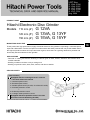
These product are high-performance, highly functional electronic disc grinders incorporating a 1500-watt power
input and a slide switch. We aim to expand our market share with these products that can provide added value in
the high-end product markets in Europe and other regions, where there is a growing demand for powerful and
functionally advanced electronic disc grinders.
LIST Nos.
G 12VA : E296
G 13VA : E297
G 13YF: E299
G 15VA : E298
G 15YF: F201
Aug. 2009
PRODUCT NAME
Hitachi Electronic Disc Grinder
Models 115 mm (4”) G 12VA
125 mm (5”) G 13VA, G 13YF
150 mm (6”) G 15VA, G 15YF
• Removal of casting fins and the finishing of various types of steel, bronze, aluminum and various othe
r
metallic materials
• Grinding of welds or sections cut by a cutting torch
• Grinding of synthetic resins, slate, brick, marble, and other materials
MARKETING OBJECTIVE
APPLICATIONS
SELLING POINTS
[ NEW FEATURES ]
Equipped with four existing electronic controls
+ two most advanced controls
1. Constant speed control
2. Soft-start speed control
3. Variable speed control (G 12VA, G 13VA and G 15VA)
4. Overload protection control
+
5. Kickback protection control
6. 0-voltage restart protection control
Equipped with most powerful motor in its class
Excellent overload durability (G 13VA)
Sales Division
SPECIFICATIONS AND PARTS ARE SUBJECT TO CHANGE FOR IMPROVEMENT.
G

REMARK:
• For more information about HANDLING INSTRUCTIONS, visit our website at:
http://www.hitachi-koki.com/manual_view_export/
• Throughout this TECHNICAL DATA AND SERVICE MANUAL, a symbol(s) is(are) used in the place of
company name(s) and model name(s) of our competitor(s). The symbol(s) utilized here is(are) as follows:
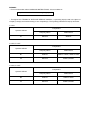
G 12VA
Competitors
Symbols Utilized
Company Name Model Name
C1 MAKITA 9564CV
G 13VA, G 13YF
Competitors
Symbols Utilized
Company Name Model Name
B1 BOSCH GWS14-125CIE, GWS14-125CI
C2 MAKITA 9565CV, 9565C
G 15VA, G 15YF
Competitors
Symbols Utilized
Company Name Model Name
B2 BOSCH GWS14-150CI
C3 MAKITA 9566CV, 9566C

CONTENTS
Page
SELLING POINT DESCRIPTIONS ----------------------------------------------------------------------------------------- 1
SPECIFICATIONS -------------------------------------------------------------------------------------------------------------- 2
COMPARISONS WITH SIMILAR PRODUCTS-------------------------------------------------------------------------- 3
PRECAUTIONS ON SALES PROMOTION ------------------------------------------------------------------------------ 6
1. Safety Instructions ----------------------------------------------------------------------------------------------- 6
2. Control Circuit Functions and Operation ------------------------------------------------------------------- 7
3. Precautions on Usage ------------------------------------------------------------------------------------------ 8
4. Operation Phenomena to Note in Sales Promotion------------------------------------------------------ 9
REPAIR GUIDE---------------------------------------------------------------------------------------------------------------- 11
1. Precautions on Disassembly and Reassembly --------------------------------------------------------- 11
STANDARD REPAIR TIME (UNIT) SCHEDULES-------------------------------------------------------------------- 17
Assembly Diagram for G 12VA
Assembly Diagram for G 13VA
Assembly Diagram for G 13YF
Assembly Diagram for G 15VA
Assembly Diagram for G 15YF

-1-
Equipped with four existing electronic controls + two most
advanced controls
These products are highly functional electronic disc grinders that provide added value and incorporate a
microcomputer with a new original program loaded in place of a conventional general-purpose IC, four fully
updated control features—(1) constant speed control, (2) soft-start speed control, (3) variable speed control
(on Models G 12VA, G 13VA and G 15VA), and (4) overload protection control—and two new additional
control features—(5) kickback protection control and (6) 0-voltage restart protection control.
1. Constant speed control
The constant speed control feature maintains constant rotation speed during operation to ensure highly
efficient work.
2. Soft-start speed control
The soft-start speed control feature reduces the reactive force generated at motor startup so as to lessen
the load on the operator's hands.
3. Variable speed control (G 12VA, G 13VA and G 15VA only)
The variable speed control feature selects an appropriate rotation speed for different applications to
ensure highly efficient work.
4. Overload protection control
The overload protection feature shuts off power to the motor in the event of motor overload or a
conspicuous reduction in rotation speed during operation. This feature thus reduces the risk of motor
burnout and controller failure.
5. Kickback protection control
The kickback protection feature cuts off power to the motor and stops the power tool in the event of a
sudden drop in wheel rotation speed during operation (e.g., wheel locking during cutting operation). This
feature thus lessens the load on the operator's hands.
6. 0-voltage restart protection control
The 0-voltage restart protection feature disables motor startup even with the main switch on when the
power cord is reconnected to the power outlet after being unplugged during operation or when the power
supply is recovered from power failure. This feature thus minimizes accidents due to motor restart.
Equipped with most powerful motor in its class
These products are equipped with a high-performance, powerful motor featuring the highest input and
output in its class to enable highly efficient work.
Maker
HITACHI
Model
G 12VA, G 13VA, G 13YF,
G 15VA and G 15YF
B1, B2 C1, C2, C3
Power input 1500W 1400W 1400W
Max power output 2800W 2100W 2650W
Excellent overload durability (G 13VA)
The Model G 13VA provides the highest overload durability in its class (1.2 times higher than that of B1)
thanks to an improved cooling mechanism and a high-power motor.
116
100
123
0 50 100 150
SELLING POINT DESCRIPTIONS
G 13VA
B1
C2
Practical test data: Com
p
arison of tor
q
ue at 200-K rise in stator coil tem
p
erature

-2-
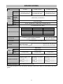
Model G 12VA G 13VA, G 13YF G 15VA, G 15YF
Dimensions
O.D. 115 mm (4-1/2”)
x thickness 6 mm (1/4”)
x I.D. 22.2 mm (7/8”)
O.D. 125 mm (5”)
x thickness 6 mm (1/4”)
x I.D. 22.2 mm (7/8”)
O.D. 150 mm (6”)
x thickness 6 mm (1/4”)
x I.D. 22.2 mm (7/8”)
Max.
practical
peripheral
speed
4,800 m/min (15,756 ft/min)
Type
27 (A, 36, Q, BF)
Depressed
center
wheels
Spindle
thread
U.S.A., Canada: 5/8-11 UNC Other countries: M14 x 2
Power source
AC single phase 50 or 60Hz
Voltage and power input
No-load speed
G 12VA, G 13VA: 2,800 to 10,500/min
G 13YF: 10,500/min
G 15VA: 2,300 to 9,000/min
G 15YF: 9,000/min
Type of motor
AC single-phase commutator motor
Enclosure
Housing (black)
Tail cover (green)
Gear cover, Packing gland ---------------------------- Aluminum alloy die-casting
Type of switch
Slide switch
Net *
2.0 kg (4.4 lbs.)
Weight
Gross
2.9 kg (6.4 lbs.) 3.0 kg (6.6 lbs.) 3.1 kg (6.8 lbs.)
Type of packing
Corrugated cardboard box, Plastic case
Standard accessories
Depressed center wheel
115 mm (4-1/2”) ----- 1
Side handle ---------- 1
Wrench ---------------- 1
Hex wrench ---------- 1
Depressed center wheel
125 mm (5”) ------------- 1
Side handle ------------- 1
Wrench ------------------- 1
Hex wrench ------------- 1
Depressed center wheel
150 mm (6”) ------------- 1
Side handle -------------- 1
Wrench ------------------- 1
Hex wrench -------------- 1
Optional accessories
Super washer(code No.310338)
* Net weight excludes the cord, side handle, depressed center wheel, wheel nut, wheel washer and wheel
guard.
Voltage (V) Current (A) Power input (W)
110 13.7 1430
120 13.0 1500
127 12.4 1500
230 7.0 1500
240 6.3 1430
SPECIFICATIONS
-----------------------------
Polyamide resin with glass fib
e
r

-3-
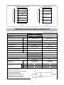
• Relation between dial settings and rotation speeds of Models G 12VA, G 13VA and G 15VA (Reference)
(Superior specifications:
)
Maker HITACHI
Model name G 12VA
C1
Capacity:
Dia. of depressed center wheel
(mm) 115 (4-1/2”) 115 (4-1/2”)
Power Input
*1
(W) 1,500 1,400
Power output
*1
(W) 850 570
Max power output
*1
(W) 2,800
2,650
No-load speed
*1
(/min) 2,800 to 10,500
2,800 to 11,000
No-load sound pressure level
*1
(dB) 86 84
Service life of carbon brushes
*2
(hrs.) 74 73
0-voltage restart protection Provided None
Kickback protection Provided None
Tool-less wheel guard Provided Provided
Anti-vibration side handle
*3
Provided None
Weight
*4
(Actual weight)
(kg)
2.0 (4.4 lbs.)
2.9 (6.4 lbs.)
1.9 (4.2 lbs.)
2.7 (6.0 lbs.)
L (mm) 297.5 (11-45/64”) 299.0 (11-25/32”)
Dimensions H (mm) 70.0 (2-3/4”) 80.0 (3-9/64”)
P (mm) 220.0 (8-21/32”) 212.0 (8-11/32”)
*1
Depends on the market
*2
Service life of carbon brushes based on
continuous rated load test
*3
Except for (HKU) & (HTM)
*4
Weight without cord, side handle,
depressed-center wheel, wheel nut,
wheel washer and wheel guard
0
2000
4000
6000
8000
10000
123456
COMPARISONS WITH SIMILAR PRODUCTS
0
2000
4000
6000
8000
10000
12000
123456
DIAL
DIAL
Spindle Rotation Speed (/min.)
Spindle Rotation Speed (/min.)
Model G 15VA
Models G 12VA and G 13VA
H
L
P

-4-
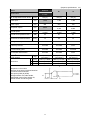
(Superior specifications:
)
Maker HITACHI
Model name
G 13VA
G 13YF
B1 C2
Capacity:
Dia. of depressed center wheel
(mm) 125 (5”) 125 (5”) 125 (5”)
Power Input
*1
(W) 1,500 1,400 1,400
Power output
*1
(W) 850 593 570
Max power output
*1
(W) 2,800
2,100 2,650
No-load speed
*1
(/min)
2,800 to 10,500
10,500
2,800 to 11,000
11,000
2,800 to 11,000
11,000
No-load sound pressure level
*1
(dB) 86 91 84
Service life of carbon brushes
*2
(hrs.) 74 80 73
0-voltage restart protection Provided Provided None
Kickback protection Provided Provided None
Tool-less wheel guard Provided Provided Provided
Anti-vibration side handle
*3
Provided Provided None
Weight
*4
(Actual weight)
(kg)
2.0 (4.4 lbs.)
3.0 (6.6 lbs.)
1.8 (4.0 lbs.)
3.0 (6.6 lbs.)
1.9 (4.2 lbs.)
2.8 (6.2 lbs.)
L (mm) 297.5 (11-45/64”) 298.0 (11-47/64”) 299.0 (11-25/32”)
Dimensions H (mm) 70.0 (2-3/4”) 70.0 (2-3/4”) 80.0
(3-9/64”)
P (mm) 220.0 (8-21/32”) 212.0 (8-21/32”) 212.0 (8-11/32”)
*1
Depends on the market
*2
Service life of carbon brushes based on
continuous rated load test
*3
Except for (HKU) & (HTM)
*4
Weight without cord, side handle,
depressed-center wheel, wheel nut,
wheel washer and wheel guard
H
L
P

-5-
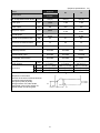
(Superior specifications:
)
Maker HITACHI
Model name
G 15VA
G 15YF
B2 C3
Capacity:
Dia. of depressed center wheel
(mm) 150 (6”) 150 (6”) 150 (6”)
Power Input
*1
(W) 1,500 1,400 1,400
Power output
*1
(W) 850 593 570
Max power output
*1
(W) 2,800
2,100 2,650
No-load speed
*1
(/min)
2,300 to 9,000
9,000
9,300
-
4,000 to 9,000
9,000
No-load sound pressure level
*1
(dB) 86 91 84
Service life of carbon brushes
*2
(hrs.) 74 80 73
0-voltage restart protection Provided Provided None
Kickback protection Provided Provided None
Tool-less wheel guard Provided Provided Provided
Anti-vibration side handle
*3
Provided Provided None
Weight
*4
(Actual weight)
(kg)
2.0 (4.4 lbs.)
3.1 (6.8 lbs.)
1.8 (4.0 lbs.)
3.1 (6.8 lbs.)
1.9 (4.2 lbs.)
2.9 (6.4 lbs.)
L (mm) 297.5 (11-45/64”) 298.0 (11-47/64”) 299.0 (11-25/32”)
Dimensions H (mm) 70.0 (2-3/4”) 70.0 (2-3/4”) 80.0
(3-9/64”)
P (mm) 220.0 (8-21/32”) 212.0 (8-21/32”) 212.0 (8-11/32”)
*1
Depends on the market
*2
Service life of carbon brushes based on
continuous rated load test
*3
Except for (HKU) & (HTM)
*4
Weight without cord, side handle,
depressed-center wheel, wheel nut,
wheel washer and wheel guard
H
L
P

-6-
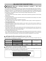
1. Safety Instructions
In the interest of promoting the safest and most efficient use of the Models G 12VA, G 13VA, G 13YF,
G 15VA and G 15YF Electronic Disc Grinders by all of our customers, it is very important that when
concluding a sale that the salesperson carefully ensure that the buyer seriously recognizes the importance
of the Handling Instructions, and fully understands the precautions listed on the Name Plate or Caution
Plate attached to each tool.
A. Handling instructions
Although every effort is made in each step of design, manufacture, and inspection to provide protection
against safety hazards, the dangers inherent in the use of any electric power tool cannot be completely
eliminated. Accordingly, the Handling Instructions list general precautions and suggestions on the use of
electric power tools, and specific precautions and suggestions on the use of the disc grinders in order to
enhance the safe, efficient use of the tools by the customer.
Salespersons must be thoroughly familiar with the contents of the Handling Instructions in order to offer
appropriate guidance to customers during sales promotion activities.
(1) Checking the power source voltage
Ensure that the power source voltage complies with the power specifications listed on the Name Plate.
Never operate the Models G 12VA, G 13VA, G 13YF, G 15VA and G 15YF using a direct current (DC)
power source. The control circuit in these tools functions through a phase-control system utilizing a triac,
and will not function under the application of DC power.
Any subsequently uncontrolled increase in motor rotation speed could be extremely hazardous.
Do not operate these tools from an engine generator, booster or any other type of transformer. Doing so
may not only damage the grinder, but may also lead to accidents.
NOTE: When the tool is connected to the power supply, the built-in electronic control circuit shifts
to standby status and the grinder becomes slightly warm, though not a malfunction.
B. Caution on Name Plate
Each tool is provided with a name plate that contains the following basic safety precautions on use of the
tool.
[For Europe]
[For New Zealand and Australia]
CAUTION
Read thoroughly read HANDLING INSTRUCTIONS before use.
PRECAUTIONS ON SALES PROMOTION

-7-
[For the U.S.A. and Canada]
WARNING
To reduce the risk of injury, user must read and understand instruction manual.
Always use guards and wear eye protection.
Use only accessories rated at least * /min.
AVERTISSEMENT
Afin de reduire le risque de blessures, I'utilisateur doit lire et bien comprendre le mode d'emploi.
Utilisez toujours un outil muni d'un protecteur et portez des lunettes on une visiere.
N'utilisez que des accessoires prevus pour au moins * /min.
* G 12VA : 13,300
G 13VA, G 13YF : 12,000
G 15VA, G 15YF : 10,200
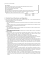
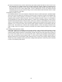
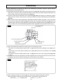
2. Control Circuit Functions and Operation
(1) The control circuit generally consists of four components (see Fig. 1). The following describes the
function and operation of each circuit component:
(a) Rotation speed detector
The rotation speed detector generates a signal whose frequency is in proportion to the motor rotation
speed.
A magnetic sensor within the controller assembly detects flux changes due to the magnet built into
the rotor assembly, and generates the frequency signal.
(b) Variable resistor
The variable resistor applies a reference voltage to the microcomputer in order to determine the no-
load speed (reference rotation speed).
(c) Triac
A trigger signal from the microcomputer determines the conduction angle of the triac, according to
which voltage is applied to the motor.
(d) Microcomputer
Under program control, the microcomputer generates trigger signals to turn the triac on and off
according to frequency signals from the rotation speed detector, the reference rotation speed
specified by the variable resistor, and the on or off state of the main switch.
The microcomputer performs the following controls based on precise trigger signal control:
• Soft-start speed control: The microcomputer generates trigger signals so that the triac's conduction
angle is gradually increased until motor speed reaches the reference rotation speed.
• Constant speed control: The microcomputer generates trigger signals so that motor speed, even if
varied, approximates the reference rotation speed. In other words, the microcomputer enlarges the
triac's conduction angle to increase voltage applied to the motor when motor load increases,
thereby lowering the rotation speed. In this way, motor speed becomes closer to the reference
rotation speed.
• Overload protection control: For overload protection, the microcomputer issues a command to shut
off power to the motor when the motor is placed under a heavier load during operation or the triac's
conduction angle exceeds a preset limit, thereby significantly lowering the rotation speed below a
preset minimum rotation speed.
• Kickback protection control: For kickback protection, the microcomputer computes the drop in
rotation speed per a specified length of time when the tool attached to the grinder receives a load
large enough to immediately stop the tool's rotation during operation, and issues a command to
shut off power to the motor if this computed drop exceeds a preset drop limit.
• 0-voltage restart protection control: For 0-voltage restart protection, the microcomputer issues a
command to shut off power to the motor to disable motor restarting once power is restored after
being cut off, even if the main switch is on (since it detects the on and off states of the main
switch) .

-8-
G 13V
A
*1
G 13YF
*2
G 13V
A
*1
G 13V
A
*1
*1 : G 12VA, G 15VA
*2 : G 15YF
(2) Motor characteristics and voltage applied to the motor
Phase control voltage waveform
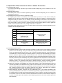
3. Precautions on Usage
(1) Never press the pushing button while the depressed center wheel is rotating.
Pressing the pushing button during depressed center wheel rotation will immediately stop the spindle. In
such case, the wheel nut may become loose and the depressed center wheel could suddenly fly off,
possibly causing serious injury.
(2) Using this product near a welding machine may cause the motor rotation speed to fluctuate. Since the
control circuit of this product includes a magnetic sensor (to detect flux changes) and a triac (which may
malfunction due to noise), instruct the customer not to use this product near a machine that generates
electromagnetic noise or near an extremely strong magnetic field.
Fig. 2
Fig. 1

-9-
4. Operation Phenomena to Note in Sales Promotion
(1) Constant speed control
The rotation speed during operation may fluctuate somewhat depending on the conditions of use and
power source.
(2) Soft-start speed control
Immediately after startup, the rotation speed may fluctuate somewhat depending on the conditions of
use and power source.
(3) Variable speed control (G 12VA, G 13VA and G 15VA)
For adjusting the number of revolutions, the models above (G 12VA, G 13VA and G 15VA) are
equipped with an electronic infinite-variable-speed drive by which the number of revolutions can be
changed according to specific use. For example, turning and setting the dial scale to 6 increases the
number of revolutions; turning and setting it to 1 decreases the number of revolutions. Before using the
tool, use the dial to set the number of revolutions. Refer to the following table as a rough guide. Be
careful not to turn the dial scale to any setting value below 1 or above 6.
Immediately after shifting gear in the tool, the rotation speed may fluctuate somewhat depending on the
conditions of use and power source.
Dial Use Tools
1 Polishing, finishing
2
3
4
Removal of paint or other coating
Removal of rust
Removal of burrs
Radial grinding disc
Sanding disc
5 Grinding Depressed center wheel
6
Rough grinding
Cutting
Depressed center wheel
Diamond wheel
(4) Overload protection control
(a) Overload protection control tends to be easily actuated by certain types of work. Applying excessive
pressure on the tool during cutting or similar heavy-duty operation will actuate overload protection
control and automatically stop the motor. This is because overload protection control detects the
increased flow of current caused by excessive pressure on the tool, and automatically turns off the
motor to protect it against possible overload burnout. The customer should be advised that the
Models G 12VA, G 13VA, G 13YF, G 15VA and G 15YF are specifically designed to perform more
efficiently and faster with considerably less pressure applied than that required for conventional disc
grinders, and that skillful use of the tools with minimal applied pressure will avoid actuating overload
protection control. The customer should also be advised, however, that the overload protection
control feature cannot always prevent overload motor burnout under all possible use conditions.
(b) Instruct the customer to immediately turn off the main switch in case overload protection control is
actuated, separate the tool attached to the grinder from the workpiece, turn on the main switch, wait
until the rotation speed increases to normal speed, and then resume work. Also advise the customer
that overload protection control will quickly reactuate even under a slight load if the customer
resumes work before the rotation speed increases to the normal level.
(c) When beginning operation, note that you may inadvertently turn on the switch immediately after
pressing the depressed center wheel or cut-off wheel against the workpiece before the tool reaches
full rotation speed. (This will actuate overload protection control. Therefore, strongly recommend that
the customer never turn the switch on with the depressed center wheel in contact with the workpiece
or press the wheel against the workpiece when beginning operation until normal rotation speed has
been attained.)

-10-
(d) Control circuit failure may result in abnormally high rotation speed. Should the control circuit in the
tool malfunction, the rotation speed may increase excessively, thereby rendering continued use of
the tool extremely hazardous. In such case (of abnormally high rotation speed), the operator will hear
abnormal noise from the motor and/or gears. If such a phenomenon occurs, the customer should
immediately shut off the tool, and then bring it to the nearest Hitachi authorized sales outlet or repair
center for inspection and repair.
(5) Kickback protection control
For kickback protection, the microcomputer computes the drop in rotation speed per a specified length
of time when the tool attached to the grinder is placed under a load large enough to immediately stop
the tool's rotation during operation, and issues a command to shut off power to the motor if this
computed drop exceeds a preset drop limit. Conversely, kickback protection control is not actuated if
the computed drop is less than the preset drop limit. In either case, overload protection control may be
actuated several seconds later to stop the motor. Instruct the customer to immediately turn off the main
switch in case kickback protection control is actuated, separate the tool attached to the grinder from the
workpiece, turn on the main switch, wait until the rotation speed increases to normal speed, and then
resume work. Also advise the customer that overload protection control will quickly reactuate even
under a slight load if the customer resumes work before the rotation speed increases to the normal
level.
(6) 0-voltage restart protection control
Instruct the customer to immediately turn off the main switch in case 0-voltage restart protection control
is actuated, separate the tool attached to the grinder from the workpiece, turn on the main switch, wait
until the rotation speed increases to normal speed, and then resume work. Also instruct the customer to
turn off the main switch and not to use this product near a machine that generates electromagnetic
noise, near an extremely strong magnetic field, or under stormy weather conditions with thunder or
lightning because the microcomputer could malfunction due to noise and 0-voltage restart protection
control may not be actuated correctly. Note that 0-voltage restart protection control may not be actuated
in case of momentarily power failure.

-11-
Before attempting disassembly or reassembly, always remember to turn off the power switch and
disconnect the plug from the power source outlet.
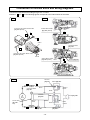
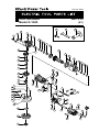
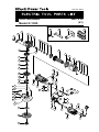
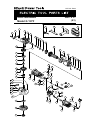
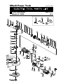
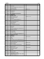
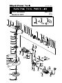
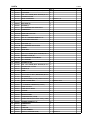
1. Precautions on Disassembly and Reassembly
The [Bold] numbers in the descriptions below correspond to numbers in the Parts List and exploded
assembly diagrams for the Models G 12VA, G 13VA, G 13YF; the <Bold> numbers correspond to those in
the Parts List and exploded assembly diagrams for the Models G 15VA and G 15YF.
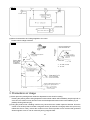
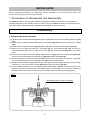
1. Disassembly of the armature
(1) Loosen the Hex. Socket Hd. Bolt (W/Washers) M5 x 20 [31] <32> and remove the Wheel Guard Ass’y [34]
<35>.
(2) Loosen the two Tapping Screws (W/Flange) D4 x 50 (Black) [59] <60> and remove the Tail Cover [57]
<58>.
(3) Remove the two Carbon Brushes [42], [43] <43>, <44> from the Carbon Brush Holders [41] <42>.
(4) Remove the four Tapping Screws D5 x 25 (Black) [2] <1>. The Armature [11] <12> can then be
removed simultaneously with the Gear Cover Ass'y [4] <5>, Packing Gland [25] <26>, and related
parts.
(5) Remove the four Seal Lock Screws (W/Sp. Washer) M5 x 16 [26] <27>. The Packing Gland [25] <26>
can then be removed together with Spindle (A) [28] <29> and the Gear [19] <20>.
(6) After removing the two Seal Lock Screws (W/Sp. Washer) M4 x 10 [1] <3>, the Armature [11] <12>
can be extracted together with the Bearing Cover [10] <11> and related parts.
(7) Carefully wrap the Armature [11] <12> in a soft, clean rag to protect it against damage, and then clamp
it securely in a vise. Then remove the Nut [5] <6> and extract the Pinion [19] <20>.
(8) For the models indicated in Fig. 3, Ball Bearing 629T12DDC3PS2-L [8] <9> can be removed from the
Armature [11]
<12> by utilizing the J-204 Bearing Puller (special repair tool, Code No. 970982) as
illustrated. After removing the ball bearing, you can easily remove the Bearing Cover [10] <11>.
Disassembly
REPAIR GUIDE
Fig. 3
J204 bearing puller (Code No. 970982)

-12-
2. Disassembly of the dust seal
(1) Remove the Magnet [18] <19>. (Note that the magnet features a left-hand thread.)
(2) Insert the hooks of the J-204 Bearing Puller between the commutator and Dust Seal (A) [16] <17> from
both sides, and then fix the hooks with the wing bolts.
(3) Place the J-204 Bearing Puller on a supporting jig and push down on the armature shaft with a hand
press to remove Dust Seal (A) [16] <17> together with Ball Bearing 608VVC2PS2L [17] <18>. Replace
Dust Seal (A) [16] <17> with a new one, since it will be damaged by removing Ball Bearing
608VVC2PS2L [17] <18>.
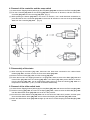
3. Disassembly of the gear
(1) Loosen the four Seal Lock Screws (W/Sp. Washer) M5 x 16 [26] <27>, and then remove the Packing
Gland [25] <26> together with Spindle (A) [28] <29> and the Gear [19] <20> from the Gear Cover Ass'y
[4] <5> as a single body.
(2) When necessary to remove the Gear [19] <20> from Spindle (A) [28] <29>, it is highly recommended to
use the special repair tools described below. As illustrated in Fig. 4 support the angled surface of the
Gear [19] <20> with the J-129-2 Gear Puller (special repair tool, Code No. 970906), rest the J-129-2
Gear Puller on the J-130 Sleeve (special repair tool, Code No. 970907), and then push down on the tip
of Spindle (A) [28] <29> with a hand press to remove the Gear [19] <20>.
Fig. 4

-13-
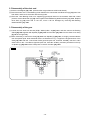
4. Removal of the controller and the snap switch
(1) Loosen the two Tapping Screws (W/Flange) D4 x 50 (Black) [59] <60> and remove the Tail Cover [57] <58>.
(2) Turn the Controller [53] <54> for the Housing [39] <40> in the arrow "A" direction, and then remove the
Controller [53] <54> from the Housing [39] <40>. (Fig. 5)
(3) While pressing the Switch [49] <50> in the arrow "A" direction, use a small flat-blade screwdriver to
press the latches of the Controller [53] <54> in the arrow "B" direction to remove the snap Switch [49]
<50> from the Controller [53] <54>. (Fig. 6)
5. Disassembly of the stator
(1) After removing the Armature [11] <12>, disconnect the lead wires connected to the carbon Brush
Holders [41] <42>, and then remove the Connector 50091 [52] <53>.
(2) Remove the Fan Guide [12] <13> from the Housing [39] <40>.
(3) Loosen the two Hex. Hd. Tapping Screws D4 x 70 [13] <14>, and then remove the Stator [14] <15> and
Internal Wire [51] <52> from the Housing [39] <40>. If the Stator [14] <15> proves difficult to remove
from the Housing [39] <40>, use an appropriate heating device to heat the Housing [39] <40> to a
temperature of about 60¶C (140¶F) in order to facilitate disassembly.
6. Removal of the slide switch knob
(1) Loosen the two Tapping Screws (W/Flange) D4 x 50 (Black) [59] <60> and remove the Tail Cover [57] <58>.
(2) Hold the Housing [39] <40> and remove the Spring [46] <47>, and then raise the Slide Bar [47] <48>
until the Slide Switch Knob [38] <39> moves to the "ON" position.
(3) Check that the Slide Switch Knob [38] <39> has not moved to the "ON-LOCK" position, and then push
down the Slide Switch Knob [38] <39> until it clicks while keeping the Slide Bar [47] <48> raised.
(4) Raise the Slide Switch Knob [38] <39> straight up and remove it while keeping the Slide Bar [47] <48>
raised.
Fig. 5 Fig. 6

-14-
Perform reassembly by reversing the order of the disassembly procedure. However, special attention
should be given to the following items.
(1) Generously lubricate the teeth of the Gear and Pinion set [19] <20> with grease. Rub grease onto the
teeth with your fingers so that it reaches the bottom of each tooth. Note that insufficient lubrication may
result in faster wear of the Gear and Pinion set [19] <20>.
(2) Be sure to soak the inner diameter of the Felt Packing [24] <25> with machine oil. Otherwise, its dust-
sealing function will fail to work properly, resulting in premature damage to Ball Bearing 6201DDCMP2L
[23] <24>.
(3) When replacing the Armature [11] <12> or Ball Bearing 608VVC2PS2L [17] <18> on the commutator
side, be sure to replace Dust Seal (A) [16] <17> with a new one together. Dust Seal (A) [16] <17> is an
important part to ensure the dust resistance of the ball bearing. Replace Dust Seal (A) [16] <17> with a
new one without fail. Press-fit Ball Bearing 608VVC2PS2L [17] <18> into the position shown in Fig. 7.
(4) Apply Three Bond TB 1406 Screw Locking Agent to the following screws:
• Two Seal Lock Screws (W/Sp. Washer) M4 x 10 [1] <3> that secure the Bearing Cover [10] <11> in
place.
• Three Seal Lock Screws (W/Sp. Washer) M4 x 8 [21] <22> that secure the Bearing Cover (B) [22]
<23> in place.
• Four Seal Lock Screws (W/Sp. Washer) M5 x 16 [26] <27> that secure the Packing Gland [25] <26>
in place.
(5) Check that the end of the spring does not hold the pigtail when mounting the carbon brush. Do not catch
the pigtail in the tail cover when mounting the cover as shown in Fig. 8 below.
(6) When replacing the Gear Cover Ass'y [4] <5>, lubricate the needle bearing with mixed oil.
Mixed oil: Mixture of Hitachi power tool grease No. 2 (Unilube No. 00) and turbine oil
• Mixed ratio ------- 1:1 (weight ratio) • Volume ---------- 0.5 cc
Reassembly
Fig. 7
Press-fitting position:
4.2 to 4.5 mm
Thrust Washer [15] <16>
Dust Seal (A) [16] <17>
Ball Bearing
608VVC2PS2L [17] <18>
A
rmature shaft
Magnet [18] <19>
Fig. 8

-15-
Fig. 10
Connect the internal wires according to Figs. 9 to 11 below.
Numbers 1 to 4 in the following figures correspond to the internal wires of the stator.
Connection of internal wires and wiring diagrams
4
3
2
1
Pillar Terminal [48] <49>
Connector 50091
[52]
<53>
Terminal [60] <61>
Carbon Brush Holder
[41] <42> (Side B)
Carbon Brush Holder
[41] <42> (Side A)
Side A
Side B
Connect to the Carbon Brush Holder
[41] <42> (Side A)
1
2
3
4
Connect to the Carbon Brush Holder
[41] <42> (Side B)
Controller
[53] <54>
Connector 50091
[52] <53>
Pillar Terminal
[48] <49>
Connector 50091
[
52
]
<53>
Internal Wire
[51] <52>
Gray
Terminal
[
60
]
<61>
Cord [63] <64>
Switch [49] <50>
Blue or
White
White or
Brown
Black
or Blue
Black
Black
Gray
Red
White
Brown
2
3
4
1
Fig. 11
Fig. 9

-16-
Pinion chamber of the Gear Cover Ass'y [4] <5> -------COSMO MOLYBDEN No. 2 grease 22 g
Generously rub grease onto the gear and the pinion.
Needle bearing -------------------------------------------------- Mixed oil 0.5 cc
Mixed oil: Mixture of Hitachi power tool grease No. 2
(Unilube No. 00) and turbine oil
Mixed ratio1:1 (weight ratio)
Tapping Screws D4 [13] <14> [55] <56> [59] <60>------- 2.0 r 0.5 N
•m (20 r5 kgf•cm, 1.5 r 0.4 ft-lbs.)
Seal Lock Screws (W/Sp. Washer) M4 x 10 [1] <3> ------ 1.8 r 0.4 N
•m (18 r 4 kgf•cm, 1.3 r 0.3 ft-lbs.)
Tapping Screw D5 x 25 [2] <1>--------------------------------- 2.9 r 0.5 N
•m (30 r 5 kgf•cm, 2.2 r 0.4 ft-lbs.)
Seal Lock Screw (W/Sp. Washer) M4 x 8 [21] <22> ------ 2.9 r 0.5 N
•m (30 r 5 kgf•cm, 2.2 r 0.4 ft-lbs.)
Seal Lock Screw (W/Sp. Washer) M5 x 16 [26] <27>----- 3.4 r 0.7 N
•m (35 r 7 kgf•cm, 2.5 r 0.5 ft-lbs.)
Tapping Screw D3 x 10 [44] <45>------------------------------ 0.74 r 0.15 N
•m (7.5 r 1.5 kgf•cm, 0.5 r 0.1 ft-lbs.)
Magnet [18] <19> (M6 left-hand thread)---------------------- 1.27 r 0.29 N
•m (13 r 3 kgf•cm, 0.9 r 0.2 ft-lbs.)
Nut M8 [5] ----------------------------------------------------------- 13.7 r 2.0 N
•m (140 r 20 kgf•cm, 10.1 r 1.5 ft-lbs.)
Spacial Nut M6 <6> ----------------------------------------------- 5.1 r 1.0 N
•m (50 r 10 kgf•cm, 3.6 r 0.7 ft-lbs.)
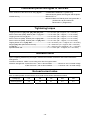
Upon completing disassembly and repair, measure the insulation resistance and conduct a dielectric
strength test.
Insulation resistance: 10M: or more using a DC 500 V megohm tester
Dielectric strength test: 4,400 VAC/3 sec., with no abnormalities ------------ More than 150 V of rated voltage
3,000 VAC/3 sec., with no abnormalities ------------ Less than 150 V of rated voltage
After no-load operation for 30 minutes, the no-load current values should be as follows.
Voltage (V) 110 120 127 230 240
Current (A) max. 4.9 4.8 4.7 2.4 2.4
Lubrication points and types of lubricant
Tightening torque
Insulation tests
No-load current value

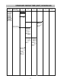
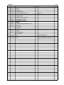
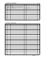
-17-
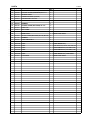
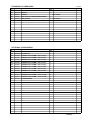
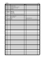
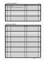
MODEL
Variable
Fixed
10 20 30 40 50 60 min.
Work Flow
G 12VA
G 13VA
G 13YF
G 15VA
G 15YF
General Assembly
Wheel Guard
Ass’y
Tail Cover
Carbon Brush
x 2
Spring x 2
Controller
Snap Switch
Cord
Cord Armor
Pinion
Ball Bearing
(629T12DD)
Bearing
Cover
Armature
Dust Seal (A)
Ball Bearing
(608VV)
Gear Cover
Ass’y
Pushing
Button
Lock Pin
Gear
Bearing
Cover (B)
Ball Bearing
(6201VV)
Felt Packing
Packing
Gland
Feather Key
Spindle
Housing
Stator
Slide Switch
Knob
Slide Bar
Spring
STANDARD REPAIR TIME (UNIT) SCHEDULES
Page is loading ...
Page is loading ...
Page is loading ...
Page is loading ...
Page is loading ...
Page is loading ...
Page is loading ...
Page is loading ...
Page is loading ...
Page is loading ...
Page is loading ...
Page is loading ...
Page is loading ...
Page is loading ...
Page is loading ...
Page is loading ...
Page is loading ...
Page is loading ...
Page is loading ...
Page is loading ...
-
 1
1
-
 2
2
-
 3
3
-
 4
4
-
 5
5
-
 6
6
-
 7
7
-
 8
8
-
 9
9
-
 10
10
-
 11
11
-
 12
12
-
 13
13
-
 14
14
-
 15
15
-
 16
16
-
 17
17
-
 18
18
-
 19
19
-
 20
20
-
 21
21
-
 22
22
-
 23
23
-
 24
24
-
 25
25
-
 26
26
-
 27
27
-
 28
28
-
 29
29
-
 30
30
-
 31
31
-
 32
32
-
 33
33
-
 34
34
-
 35
35
-
 36
36
-
 37
37
-
 38
38
-
 39
39
-
 40
40


Hitachi G15VA Technical Data And Service Manual
- Category
- Power tools
- Type
- Technical Data And Service Manual
Ask a question and I''ll find the answer in the document
Finding information in a document is now easier with AI
Related papers
-
Hitachi H41SC User manual
-
Hitachi G12S2 User manual
-
-
Hitachi PDA-100D Handling Instructions Manual
-
Hitachi G 12SE2 Handling Instructions Manual
-
Hitachi G 23SCY Handling Instructions Manual
-
-
-
-
Other documents
-
Black & Decker BEG210 User manual
-
Hikoki G12SR User manual
-
 Northern Industrial Tools 143379 User manual
-
Wen 944 User manual
-
 Confidential G Series Disc Grinder User manual
-
 Alpha Tool.Com.HK Limited 225 User manual
-
Koblenz 0060251 Operating instructions
-
-
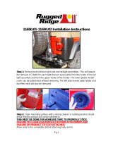 Rugged Ridge 11650.02 Installation guide
-
King Canada 8204G User manual


