Argos Home Manhattan Ceiling Fan User manual

Type
User manual

This manual is also suitable for

MANHATTAN CLEAR SAT NICKEL RC CEILING FAN
432/5114(D)
PDF compression, OCR, web optimization using a watermarked evaluation copy of CVISION PDFCompressor
MOUNTING PLATE
BALL JOINT
CANOPY
ROUND HOLE
BAYONET
SLOT
CANOPY
SCREW
FIGURE 2
ASSEMBLY & FITTING INSTRUCTIONS
IMPORTANT
Please read these instructions carefully before attempting to install this ceiling fan. It is also advis-
able to keep these instructions in a safe place for future reference.
Before installing and using this ceiling fan, read the list of Do and Don’ts below.
CAUTION
Do not use the ceiling fan and open gas heating appliances in the same room at the same time.
It is important that the correct electrical connections are made and that the mountingplate is fitted
to an adequate ceiling support. Ceiling fans are heavy, so it is important that they should be
suspended securely. If in any doubt about the installation of this product consult a qualified
electrician.
This product must be installed in accordance with national building regulations.
LOCATION
When deciding on the location for your ceiling fan make sure that there will be plenty of room for
the rotation of the fan blades and that no obstacles are likely to get in their way. The distance
betweenthe fan blades and the floor should be at least 2.3m (7½ft).
TOOLS AND MATERIALS REQUIRED
Crosshead and slotted screw drivers
1xMax.40w E14 buld(NOT INCLUDED)
Step ladder
Insulating tape
UNPACKING
Remove the upper polystyrene cover from the box .Take the motor out of the box and place it on
the polystyrene cover ,or on a soft padded surface to protect it during the installation procedure.
Keep all packing material for future protection in transit.
UNSTALLING THE MOUNTING PLATE
1.Unscrew the four screws on the ceiling canopy to release the mounting plate(Figure 1). Secure
the mounting plate to a ceiling joist ,or an equally secure ceiling structure using the two wood fix-
ing screws and washers supplied. The support for the mounting plate must be capable of safety
and securely holding the moving weight of the fan. Note that additional strengthening of the joist
might be necessary.
2.For best fan performance and safety,make sure the mounting plate is fitted to a level ceiling
joist or ceiling support. If the mounting position is not level, hard packing material should be used
to make the plate level.
INSTALLING THE FAN
1.Hang the ball joint and the fan onto the bracket. Make sure the guled pon of bracket is fitted
into slot of ball joint.(Figute 2) With the fan suspended in this manner, you can now make the
appropriate electrical connections. See the CONNECTION TO THE LIGHT CIRCUIT section.
2.insert the remote control receiver betwwen the bracket and the downrod. And the sensor as
shown.(Figure 2)
3.Fix conopy onto the bracket by tightening the screws.(Figure 4)
CONNECTION TO THE LIGHT CIRCUIT
Ensure electricity is switched off at the mains before installing or maintaining this fitting.
Any switches connected to the ceiling fan must conform to the necessary British Standards. If you
are not sure how to wire the ceiling fan consult a qualified electrician. For the basic means of
wiring the ceiling fan (model 1 above) use the following procedure(Figure 3)
Blue or black (Neutral)to the terminal marked N
Brown or Red (Live)to the terminal marked L
Green/Yellow or Green (Earth)to the terminal marked
Ensure that earth terminal of the canopy is securely connected to the earth pole of the terminal
block.
Ensure that all electrical connections are tight and that no loose strands are left out of the terminal
block. Cover the terminal block with insulation tape.
Warning : If there are only two wires in your existing mains wiring,this means that there is no
Earth. Under no circumstance should you wire up this fitting without using an Earth connection.
Ask a qualified electrician to provide an Earth facility.
The installation must be provided with a double pole switch.
FIGURE 3
DOWNROD
EARTH TERMINAL
LIGHT SUPPLY
(RED)
L
N
WIRES TO FAN
L
N
INCOMING MAINS SUPPLY
L
N
BROWN
(GREEN /YELLOW)
BLUE
1
RECEIVER
RECEIVER
MATE
CONNECTOR
FAMATE
CONNECTOR
PDF compression, OCR, web optimization using a watermarked evaluation copy of CVISION PDFCompressor
2
-Use the remote control transmitter to change the speed of the fan and to switch the light and fan
on or off.
-Replace the batteries by sliding the battery compartment cover on the romote control transmitter
in the direction of the arow,fit 2*AAA batteries ,ensure the polarity of the batteries match wit the
figures shown in the battery compartment .(Note:Batteries NOT include). Reassemble the battery
compartment cover.
-Always ensure the battery compartment cover is closed properly.
-Don’ts expose the remote control to direct sunlight
-Don’ts attempt to rechange expired bateries. There are special rechargeable batteries,which are
clearly marked with.
-Don’ts dispose of batteries in fire to avoid explosion.
REVERSE CONTROL
The fan must be switched off before this slide switch, located on the side of the switch housing is
operated.
Switch upwards for REVERSE winter operation.
Switch downwards for FORWARD summer operation.
FITTING THE LIGHT
1. Insert 40W E14 bulb (not supplied) into the lampholders. Do not use a higher wattage bulb.
2. Install the lamp shade onto the lamp holder by rotating the lamp shade clockwise.
3. The light is switched on and off by the use of remote control.(Figure 6).
CLEANING
Wipe with a soft dry cloth or use a soft brush to remove dust. Care should be taken that no water
or moisture gets into the ceiling fan. Do not use water to clean the ceiling fan.
Do not use metal polish or abrasive cleaning materials on any part. A small amount of furniture
polish can be used to clean the fan blades. When cleaning the fan blades do not apply too much
pressure on them. It is recommended that you support the ends of the blades when you clean
them.
TROUBLE SHOOTING
Fan will not start
CAUTION: Make sure mains power is switched off before you carry out these checks.
1. Check the main and branch circuit fuses or contact breakers.
2. Check power supply wires to the fan are secure.
3. Check reverse switch is firmly in the up or down position.
Fan sounds noisy
Allow a break-in period of 24 hours. Most noise associated with a new fan will disappear after
this period.
1. Check to make sure all screws to the fan motor housing are secure but not overtight.
2. Check mounting plate screws are tight and securely fitted to ceiling joist or ceiling support.
3. Check that the screws which attach the blade holder arms are tight.
4. Make sure the screws securing the lamp shade are finger tight. Check that the lamp is properly
fitted to the lampholder.
5. A dimmer switch should not be fitted to this ceiling fan. If this ceiling fan is connected to a dim-
mer switch it will make noises when the fan light is switched off. Remove the dimmer switch.
Fan wobblers or shakes excessively.
Please note that a small amount of wobble is natural and should not be considered a problem.
All blades are weighed and grouped by weight. Natural wood varies in density which could
cause the fan to wobble even though all blades are weight matched. The following procedure
should eliminate most of the wobble. Check for wobble after each step.
1. Check that fan blades are screwed firmly into the blade holder arms.
2. Check that all blade holder arms are tightened securely to the fan housing.
3. Most fan wobble problems are caused when blade tracking levels are unequal. Blade tracking
may be checked simply by use of a length of timber. Place the timber vertically against the ceiling
and even with the outside leading edge of the blade. Mark the distance from the edge of the
blade to the ceiling. Turn the blades slowly by hand to check the remaining blades. If a blade is
not in alignment, the blade holder arm may be gently bent up or down to be in-line with the other
blades. Allow the fan to operate for ten minutes to check if this problem has been solved.
4. Make sure the mounting plate is securely fixed to the ceiling joist.
5. Check that the ball joint engages with the groove on the ceiling canopy.
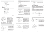
REMOTE CONTROL
ASSEMBLY OF THE FAN BLADES AND LAMP HOLDER
1Install the fan blades sets onto motor by tightening the hexagonal screws and spring washers.
2. Secure the lamp holder onto the lamp holder bracket by tightening the 3 set screws.
(CAUTION: Make sure the set screws are fitted properly into the key slots.)(Figure 5)
Attention: Ensure the star washers to be secured tightly to lamp gallery bracket with sot screws.
FIGURE 6
LAMP SHADE
LAMP HOLDER
SCREW &
SPRING WASHER
FAN MOTOR
HOUSING
SCREW &
SPRING WASHER
LAMP
HOLDER
FIGURE 5
FAN MOTOR
HOUSING
INFRARED
RAY RECEIVER
BLADE
PDF compression, OCR, web optimization using a watermarked evaluation copy of CVISION PDFCompressor
3
DO
DON’ T
Do ensure that the ceiling joist or ceiling support will hold the moving weight of the ceiling fan.
Do ensure that all electrical connections are in accordance with relevant safety and government
regulations.
Do use or consult a qualified electrician if you are uncertain about wiring this ceiling fan.
Do use a qualified electricion for installation to a concrete ceiling.
Do switch off the fan before using the reverse switch.
Don’t use the ceiling fan and open gas heating appliances in the same room at the time,
otherwise harmful gases might be circulated.
Don’t fit in rooms where the distance between floor and blades is less than 2.3m (7½ft).Allow
at least 500mm between the blade tip and any wall or fumishings.
Don’t fit in bathrooms or areas where the fan might become wet.
Don’t insert anything into the fan blades when they are rotating.
Don’t use a dimmer switch with this ceiling fan. This could damage the dimmer and the fan.
Don’t use this fan with any speed control device as it could be a fire risk.
Don’t use the ceiling fan for any other purpose than described in this instruction sheet.
Don’t modify or alter the ceiling fan.
IF IN ANY DOUBT CONSULT A QUALIFIED ELECTRICIAN
SPECIFICATIONS
Fan 55W Light fitting 1x40W. Total 95W. 230V~50Hz.
Specification subject to change without prior notice.
REPAIRS
Do not attempt to repair this unit yourself. Repairs can only be made by qualified service person-
nel. Repairs by unqualified persons will invalidate the guarantee, and may result in accident or
injury.
CEILING FAN CONTENTS LIST
Ceiling mounting plate 1
Mounting plate fixing
screws & washers 2
Canopy mounting screws, spring 4
washers & star spring washers
Switch housing 1
Mounting bracket screws
& lock washers --
Ceiling canopy 1
Fan body (motor & switch
housing) with optional downrod 1
Fan body (motor & switch
housing) with no downrod
Reversible fan blades 5
Fan blade holder
arms --
Screws and washers
for fitting blade to
fan body --
Screws, washers and nuts
for fitting blades to
blade holders --
Lamp shade 1
Lamp shade securing
screws 3
Pull chain for speed
control with wooden konb --
Pull chain for light
control with wooden
knob --
Remote control 1
Lamp holder 1
ARGOS MK9 2NW
432/5114(D)
PDF compression, OCR, web optimization using a watermarked evaluation copy of CVISION PDFCompressor
  • Page 1 1
  • Page 2 2
  • Page 3 3
  • Page 4 4

Argos Home Manhattan Ceiling Fan User manual

Type
User manual
This manual is also suitable for

Ask a question and I''ll find the answer in the document

Finding information in a document is now easier with AI