Page is loading ...

M968484
Thank you for selecting American-Standard...the benchmark of fine quality for over 100 years.
To ensure that your installation proceeds smoothly--please read these instructions carefully
before you begin.
Installation Instructions
ROUGHING-IN DIMENSIONS
7271.3017271.300
7271.5217271.571
7271.021
7
271.
5
2
1
7
271.
0
21
7271.071
7271.571
7271.071
7271.400
7271.400
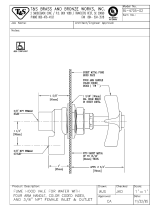
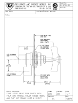
LABORATORY FUME HOOD FITTINGS
DIA.
[32mm]
1-1/4"
[89mm]
3-1/2"
DIA.
[54mm]
2-1/8"
[57mm]
2-1/4"
1-3/4"
[45mm]
[24mm]
15/16"
[67mm]
2-5/8"
3/8" NPT FEMALE
THREAD OUTLET
3/8" NPT
FEMALE
THREAD INLET
INDEX A
S
RE
QU
IRE
D
(
AIR, GAS, OR VAC
)
DIA.
[32mm]
1-1/4"
1/16"-
[2mm-32mm]
WARE THICKNESS
1-1/4"
1/16"-
[2mm-32mm]
WARE THICKNESS
1-1/4"
[89mm]
3-1/2"
DIA.
[54mm]
2-1/8"
[57mm]
2-1/4"
[24mm]
15/16"
1-3/4"
[45mm]
[57mm]
2-1/4"
3/8" NPT FEMALE
THREAD OUTLET
3/8" NPT FEMALE
THREAD INLET
INDEX 'CW'
PANEL THI
C
KNE
SS
N
O
T T
O
EX
C
EE
D
[
3mm
]
1
/
8
"
4
5
˚
3"
[76mm
]
1-
3/
4
"
[
44mm
]
[
44mm
]
1-3
/
4
"
[
51mm
]
I
A. FLAN
GE
2"
[
32mm
]
1-1
/
4
"
[
7mm
]
9
/
32
"
1-5/8" [41mm]
HEX. N
U
L
OC
K D
O
PROVIDE 1-1/2"
[
38mm
]
DIA
.
O
PENIN
G
IN PANEL T
O
A
CC
EP
T
1-7/16"
[
37mm
]
DIA. BOD
Y
IN
OUT
N
O
TE
:
I
NLET ALWAY
S
O
N B
O
TT
OM
3
/
8" NPT FEM
.
INLET THRD.
3
/
8" NPT FEM
.
OU
TLET THRD
.
INDEX A
S
RE
QU
IRE
D
(
AIR, GAS, VAC
)
[
54mm
]
2-1/8"
1
/
16"
-
[
2mm-32mm
]
WARE THICKNESS
1-1
/
4
"
[54mm]
DIA. FLAN
GE
2-1/8
DIA.
[
17mm
]
11/16
"
"
[
102mm
]
4
3/8
" NPT MALE
THREAD INLET
Product names listed herein are trademarks of American Standard Inc.
©American Standard Inc. 2004
HOTLINE FOR HELP
For toll-free information and answers to your questions, call:
1 (800) 442-1902
Weekdays
8:00 to 7:00 p.m. Eastern Time
CANADA
1-800-387-0369 (TORONTO 1-905-306-1093)

M968484
R
OUG
HIN
G
-IN DIMEN
S
I
O
N
S
T
OO
L
S
AND
SU
PPLIE
S
RE
QU
IRE
D
7271.301 7271.300
3
˚
3
˚
[29mm
]
1-1
/
8
"
[
51mm
]
2
"
[
7
3
mm
]
" DIA.
[
51mm
]
2
[
152mm
]
6"
[
273mm
]
10-3
/
4
"
[
114mm
]
4-1/2
"
[
38mm
]
1-1
/
2
"
3
/
8" NPT FEMALE
THREAD INLET
3
/
8" NPT FEMALE
THREAD INLET
[29mm
]
1-1
/
8
"
[
51mm
]
2"
[
7
3
mm
]
2-7
/
8
"
" DIA.
[
51mm
]
2
[
137mm
]
5-3/8"
[114mm
]
4-1
/
2
"
[279mm
]
11"
Adjustable Wrench
Channel Locks
Flat Blade Screwdriver
Phillips Screwdriver
Pipe Wrench
Teflon Tape
Plumbers' Putty or
Caulking
1
2
3
4
FR
O
NT-L
O
ADED VALVE F
O
R AN
G
LED PANEL
S
(
AIR, GAS, VACUUM, WATER
)
FR
O
NT-L
O
ADED VALV
E
F
O
R
S
TRAI
G
HT PANEL
S
(
AIR, GAS, VACUUM OR WATER
)
TYPI
C
AL F
U
ME H
OOD
F
U
ME H
OO
D FITTIN
GS
WALL M
OU
NTED REM
O
T
E
CO
NTR
O
L
OU
TLET FITTIN
G
For installation of
p
roducts refe
r
t
o ste
p
s one to four
.
WALL M
OU
NTED REM
O
T
E
CO
NTR
O
L
OU
TLET FITTIN
G

M
968
4
84
1
2
B
O
D
Y
S
H
OU
LDER WA
S
HE
R
H
O
LD D
O
WN N
UT
CARTRIDGE STEM
HANDLE
SC
RE
W
Im
p
ortant service note
:
T
he Faucet Panel mounted fume hood fittin
g
has been desi
g
ned such that future servicin
g
of th
e
f
ittin
g
's cartrid
g
e can be done from the (user's) side of the fume hood. To do this, insure that th
e
main suppl
y
valve to the fittin
g
has been completel
y
turned off and then pur
g
ed b
y
completel
y
o
penin
g
the fittin
g
and releasin
g
trapped material into the fume hood atmosphere. Then, suppor
t
t
he entire fittin
g
b
y
holdin
g
the hold-down nut in place with a wrench, before loosenin
g
th
e
c
artrid
g
e's cap nut
.
T
his Panel mounted fume hood valve has been shi
pp
ed as shown below to ease installation. It i
s
d
esi
g
ned to be installed in a 4
5
˚
angled fume hood equipped with 1-1/2" (38.1mm) diameter
˚
mountin
g
holes. Before proceedin
g
with the installation, identif
y
and familiarize
y
ourself with al
l
o
f the com
p
onents
.
Important Note: The front load fume hood fittin
g
s described in these installation instruction
s
a
re available in both ri
g
ht hand and left hand models. Ri
g
ht hand models are marked on bot
h
sides of the bod
y
with an "R" and left hand models are similar marked with an "L". Due to th
e
u
se of these fittin
g
s in both ri
g
ht and left hand fume hoods, the bodies are marked on bot
h
sides with directional flow arrows. Re
g
ardless of the model used, the fittin
g
s are desi
g
ned t
o
be
in
sta
ll
ed
suc
h
t
h
at
t
h
e
inl
et
i
s
o
n
t
h
e
botto
m
.
4
5
˚
AN
G
LE
D
F
U
ME H
OOD
L
OC
K N
UT
FLAN
GE
VALVE
H
OO
D M
OU
NTIN
G
H
O
L
E
C
R
OSS
HANDL
E
C
AP N
UT
PACKING NUT (7271.571 and 7271.521 ONLY)
INSTALL FRONT-LOADED ANGLE CONTROL VALVE
,
7271.021/52
1
(
AIR, GAS, VACUUM, WATER
)
INSTALL FRONT-LOADED VALVE FOR STRAIGHT PANELS
,
7271.071/571
(
AIR, GAS, VACUUM, WATER
)
HANDLE SCRE
W
N
DEX B
U
TT
ON
S
TEEL WA
S
HE
R
R
U
BBER WA
S
HE
R
B
O
D
Y
FI
GU
RE
1
S
H
OU
LDE
R
WA
S
HE
R
1-1/2"
(
38.1mm
)
M
OU
NTIN
G
H
O
L
E
H
O
LD D
O
WN N
UT
R
e
m
o
v
e
a
n
d
flan
ge
fr
o
m v
a
lv
e
.
Rubber seal washer
,
steel washe
r
a
n
d
l
oc
k n
ut
v
a
lv
e
Ali
g
n the mounted
a
r
e
in lin
e
a
n
d
t
h
e
v
a
lv
e
a
n
d
v
a
lv
e
bod
y
securel
y.
Wi
t
h v
a
lv
e
now firml
y
secured to the fume hood install the ca
p
nu
t
cro
ss
handl
e
a
n
d
secu
r
e
wi
t
h handle
s
crew
.
in
de
x
button
in
to
h
a
n
d
l
e
cou
n
te
r
bo
r
e.
Complete the inlet and outlet pipin
g
to the v
a
lv
e
a
n
d
c
h
ec
k f
o
r l
ea
k
s.
HANDLE SCREW
INDEX B
U
TT
O
N
S
(
AIR, GAS, VACUUM, WATER
)
HANDLE
S
TE
M
FI
GU
RE
2
4
5
˚
AN
G
LE
D
F
U
ME H
OOD
IMP
O
RTANT: FL
US
H ALL
SU
PPLY LINE
S
PRI
O
R T
O
FITTIN
G
IN
S
TALLATI
O
N
.
IMPORTANT: FLUSH ALL SUPPLY LINES PRIOR TO FITTING INSTALLATION.
R
e
m
o
v
e
t
h
e
h
o
l
d
-
do
wn n
ut
fr
o
m
t
h
e
body
a
n
d
t
h
e
y
handle
s
cre
w
fr
o
m
t
h
e
s
te
m
.
With a
p
air o
f
body
such that the threads on the two components lock together.
y
Pl
ace
t
h
e
fr
o
n
t
e
n
d
o
f
t
h
e
bod
y
(end which contains the operating cartridge) through the 1-1/2"
y
h
o
l
d
-
do
wn n
ut
o
n
to
t
h
e
bod
y
h
o
l
d
-
do
wn n
ut
at
t
hi
s
t
im
e.
Align the mounted fitting from the backside of the fume hood such that the
bod
y
'
s
inl
et
a
n
d
out
l
et
a
r
e
in lin
e
a
n
d
t
h
e
su
pp
ort the valve bod
y
from the backside, tighten the
y
h
o
l
d
-
do
wn n
ut
securel
y.
h
a
n
d
l
e
o
n
to
t
h
e
s
te
m
and ti
g
hten i
t
into
p
lace with the
s
cre
w
r
e
m
o
v
ed
fr
o
m
t
h
e
s
tem
.
in
de
x
button
in
to
h
a
n
d
l
e
Complete the inlet and outlet pipin
g
to the fittin
g
a
n
d
c
h
ec
k f
o
r l
ea
k
s.

7
271.
301
7
271.
300
7271.521
7271.571
7271.071
7271.021
7271.400
M968484
3
S
P
OU
T N
UT
SPOUT BOD
Y
RTRIDGE
96
2
3
2
9
-
00
7
0
A L
H
9
62330-0070A R
H
W Index
M96
2
3
12-
00
7
0A
HANDLE
M
96
2
3
1
0
-
00
2
0A
S
P
OU
T A
SS
EMBL
Y
WALL MOUNTED REMOTE
C
ONTRO
L
4
WALL MOUNTED REMOTE CONTROL OUTLET
FITTING
(
GOOSE NECK SPOUTS
)
, 7271.300/30
1
AVAILABLE REPAIR PART
S
L
OC
K N
UT
S
TEEL WA
S
HE
R
H
OO
D M
OU
NTIN
G
H
O
L
E
1-1/4" DIA.
(
32mm
)
R
e
m
o
v
e
l
oc
k n
ut
a
n
d
s
teel wa
s
he
r
from fittin
g.
Ali
g
n and moun
t
fittin
g
from the front side of the fume hood. Usin
g
fittin
g
bod
y
and install
s
tee
l
wa
s
he
r
a
n
d
l
oc
k n
ut.
ti
g
hten the l
oc
k n
ut
securel
y
.
Wi
t
h fittin
g
now firml
y
secured to the fume hood complete the i
n
pipin
g
to the fittin
g.
(See rou
g
h-in for pipin
g
requirements)
.
Turn suppl
y
to fittin
g
o
n
a
n
d
c
h
ec
k f
o
r l
ea
k
s.
Note: See roughing-in to determine pipe nipple length fro
m
s
i
de
w
a
ll
.
T
u
rn s
p
out nu
t
cou
n
te
r
c
l
oc
k-wi
se
to
l
oose
n
a
n
d
r
e
m
o
v
e
spout assembl
y
from
f
ittin
g
base
.
p
i
pe
ni
pp
l
e
(See rou
g
h-in for pipin
g
requirements)
.
Thr
ead
spout body
o
n
to
y
p
i
p
e ni
pp
l
e
and align so tha
t
s
p
ou
t
assembl
y
i
s
v
e
r
t
i
ca
l
.
Thr
ead
spout assembly
o
n
to
y
spout body
and tighten.
y
Turn suppl
y
t
o
fittin
g
o
n
a
n
d
c
h
ec
k f
o
r l
ea
k
s
.
F
U
ME H
OO
D WAL
L
F
U
ME H
OOD
WALL
VA
CUU
M BREAKE
R
REPAIR KIT
M
96
2
3
22-
00
7
0A
GOOS
ENE
C
K
S
P
OUT
M
96
2
3
1
6
-
00
2
0A
S
ERRATED TIP
S
M
96
2
3
1
8
-
00
2
0A
BREAKER SPOUT
M
96
2
3
17-
00
2
0A
FITTIN
G
3
/
8" NP
T
APPLY
S
EALAN
T
C
W In
dex
M96
2
3
12-
00
7
0A
GAS Index
M
96
2
3
1
3
-
00
AIR
M962314-00
VA
C
M
96
2
3
1
5
-
00
VA
C
In
d
M
96
2
3
1
5
-
00
7
HANDLE
M
96
2
3
1
0
-
00
2
0
G
A
S
In
M
96
2
3
1
3
-
007
AIR In
M
96
2
3
14-
007
C
ARTRID
GE
M
96
2
3
2
9
-
00
7
0A
M
96
2
330
-
00
7
0A
C
ARTRID
GE
M
96
2
336
-
00
7
0A
C
ARTR
I
M
96
2
336
-
007
C
ARE INSTRU
C
TIONS
:
DO: SIMPLY RINSE THE PRODU
C
T
C
LEAN WITH
C
LEA
R
WATER. DRY WITH A SOFT COTTON FLANNEL CLOTH.
DO NOT: CLEAN THE PRODUCT WITH SOAPS, ACID,
POLISH, ABRASIVES, HARSH CLEANERS, OR A CLOTH
WITH A COARSE SURFACE.
/