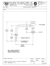
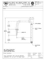
American Standard 7272 User manual

Type
User manual
7272.120
7272.120
7272.220
7272.220
7272.201
7
272.2
0
1
(
WRIST HANDLES
)
7272.221
7272.221VR
7272.221
7272.221VR
7272.121
7272.121VR
7272.121
7272.121VR
M968487
Thank you for selecting American-Standard...the benchmark of fine quality for over 100 years.
To ensure that your installation proceeds smoothly--please read these instructions carefully
before you begin.
Installation Instructions
ROUGHING-IN DIMENSIONS
SINGLE HOLE LABORATORY FITTINGS
[133mm]
5-1
/
4 "
3
˚
3"
76mm
DIA.
2
6-3
/
8
"
[
162mm
]
1/
8"
-
[3mm-35mm]
WARE THI
C
KNE
SS
60mm
2-3
/
8
"
60mm
2-3
/
8
"
DIA.
7/8 "
7/8 "
[
330mm
]
1
3
"
[
330mm
]
1
3
"
NPSM COUPLIN
G
NUT FOR 3
/
8" OR 1
/
2
"
FLEXIBLE RI
S
E
R
DEX
W'
1
6" DIA
.
[24mm]
1
/
4" DIA
.
[
6mm
]
23
/
32
"
18mm
6
[
152
m
51mm
[
324mm
]
12-3
/
4
"
[
168mm
]
6-5
/
8
"
PLAN VIEW HOLE LO
C
ATIO
N
)
DY
SHANK AND PIN
(
SINGLE CONTROL
)
1/4"
[
6mm
]
PI
N
LENGTH X 3
/
16
"
[
5mm
]
DIA
.
DEX
W'
2
3
/
[
1
8
1-1
/
8" DIA
.
29mm
1
/
4" DIA
.
[
6mm
]
"
[
152m
6
[365mm]
14-3
/
8
"
[
311mm
]
12-1
/
4
"
DIA.
27mm
[
337m
m
13-1/4"
1
/
8"-1-5
/
8
"
[3mm-41mm
]
WARE THI
C
KNE
SS
7-3
/
8"
[
187mm
]
7-1
/
8
"
[
181mm
]
PLAN VIEW HOLE LO
C
ATIO
N
FOR BODY SHANK AND PIN
(
DUEL CONTROL
)
3/8"
[
9.5mm
]
O.D. COPPER
TUBBING FOR 3/8"
[
9.5mm
]
CO
MPRE
SS
I
O
N
CO
NNE
C
TI
O
N
S
1
0"
DIA.
7/8 "
7/8 "
27mm
1-1/16
"
[365mm]
14-3
/
8
"
[
311mm
]
12-1
/
4
"
1
/
8"-1-5
/
8"
[
3mm-41mm
]
WARE THI
C
KNE
SS
m
m
]
C
KNE
SS
-
3
/
8
"
8
7mm
]
1
33mm
]
5-1
/
4"
3
˚
NPSM COUPLIN
G
O
R 3
/
8" OR 1
/
2
"
FLEXIBLE RI
S
E
R
1/4"
[
6mm
]
PI
N
LENGTH X 3
/
16
"
[
5mm
]
DIA
.
3/8"
[
9.5mm
]
O.D. COPPER
TUBBING FOR 3/8"
[
9.5mm
]
CO
MPRE
SS
I
O
N
CO
NNE
C
TI
O
N
S
3
˚
6-3
/
8"
[162mm]
L
OC
K N
UT
S
TEEL WA
S
HE
R
M968487
SINGLE AND DUAL CONTROL
LABORATORY FITTINGS
SINGLE CONTROL
LABORATORY FITTINGS
DUAL CONTROL
LABORATORY FITTINGS
1
For vandal resistant fitting only, a pin hole will be need to be drilled into the deck offset from the mounting shank hole.
Note: For vandal resistant models it is important to obtain the rough-in drawing for the particular model. The
drawing illustrates exact size and positioning of the offset hole. Drill a 1/4" (6mm) dia. hole 3/8" (10mm) deep
in mounting surface, per roughing-in dimensions for vandal resistant pin.
For vandal resistant fitting apply putty to underside of fitting base to assure a good seal and level fit.
When installing a vandal resistant fitting, align pin with pin hole in mounting surface.
For standard fitting, assemble rubber washer onto body shank.
Place body shank through hole in deck and assemble steel washer and lock nut. Tighten securely.
Pipe to correct service to complete installation.
After installation is complete turn service on and check all connections for leaks.
TOOLS AND SUPPLIES REQUIRED
Adjustable Wrench
Teflon Tape
Drill
Plumbers' Putty or
Caulking
FITTIN
G
BA
SE
P
U
TT
Y
B
O
D
Y
S
HAN
K
B
O
D
Y
S
HAN
K
FITTIN
G
BA
SE
L
OC
K N
UT
S
TEEL WA
S
HE
R
Channel Locks
7272.220
7272.201
7272.221
7272.221VR
7272.120
7272.121
7272.121VR
CARE INSTRUCTIONS:
DO: SIMPLY RINSE THE PRODUCT CLEAN WITH CLEAR
WATER. DRY WITH A SOFT COTTON FLANNEL CLOTH.
DO NOT: CLEAN THE PRODUCT WITH SOAPS, ACID, POLISH,
ABRASIVES, HARSH CLEANERS, OR A CLOTH WITH A
COARSE SURFACE.
R
U
BBER WA
S
HE
R
(
NOT USED O
N
V
R FITTINGS
)
R
U
BBER WA
S
HE
R
(
NOT USED O
N
V
R FITTINGS
)
VANDAL RE
S
I
S
TANT PI
N
O
N VANDAL RE
S
I
S
TAN
T
FITTIN
GS
O
NL
Y
O
FF
S
ET H
O
LE F
OR
VANDAL RE
S
I
S
TANT PI
N
VANDAL RESISTANT PIN
O
N VANDAL RE
S
I
S
TAN
T
FITTIN
GS
O
NL
Y
O
FF
S
ET H
O
LE F
OR
VANDAL RE
S
I
S
TANT PI
N
P
U
TT
Y
IMPORTANT: FLUSH ALL SUPPLY LINES PRIOR TO FITTING INSTALLATION.
M968487
CARTRIDGE
M
96
2
330
-
00
7
0
A R
H
EC
K MT
G
. KI
T
96
2
3
1
9
-
00
7
0A
SU
PPLY T
U
BE
S
M
96
2
3
2
6
-
00
7
0A
E
M962329-0070A LH
CO
LD WATER INDE
X
M962312-0070A
H
O
T WATER INDE
X
M
96
2
3
11-
00
7
0A
S
ERRATED
T
M
96
2
3
1
8
-
00
2
0
W
RI
S
T BLADE
C
ARTRID
GE
M
96
2
3
27-
00
2
0
A L
H
WRI
S
T BLADE
C
ARTRID
GE
M962328-0020A R
H
HANDLE
M
96
2
3
1
0
-
00
2
0A
AVAILABLE REPAIR PART
S
DUAL CONTROL
LABORATORY FITTINGS
7
272.22
0
(with GN Spout)
7272.221
7272.221VR
(with Vac.
Brkr. Spout)
7272.201
(With Vac. Brkr.
Wrist Handles.)
G.N. SPOUT
A
SS
EMBL
Y
M
96
2
3
17-
00
7
0A
SERRATED TIP
M
96
2
3
1
8
-
00
2
0
VA
CUU
M BREAKE
R
REPAIR KIT
M
96
2
3
22-
00
7
0A
VA
CUU
M BRKR
.
S
P
OU
T A
SS
EMBL
Y
M
96
2
3
17-
00
7
0A
S
ERRATED
T
M962318-0020
VA
CUU
M BREAKE
R
REPAIR KIT
M
96
2
3
22-
00
7
0A
VACUUM BRKR
.
SPOUT ASSEMBL
Y
M962317-0070
A
DE
C
K MT
G
. KI
T
M
96
2
3
1
9
-
00
7
0A
SU
PPLY T
U
BE
S
M
96
2
3
2
6
-
00
7
0A
M968487
C
ARTRID
GE
M
96
2
3
2
9
-
00
7
0
A LH
CO
LD WATER INDE
X
M
96
2
3
12-
00
7
0A
Product names listed herein are trademarks of American Standard Inc. © A m e r i c a n Standard Inc. 2004
HOTLINE FOR HELP
For toll-free information and answers to your questions, call:
1 (800) 442-1902
Weekdays
8:00 to 7:00 p.m. Eastern Time
CANADA
1-800-387-0369 (TORONTO 1-905-306-1093)
HANDLE
M
96
2
3
1
0
-
00
2
0A
AVAILABLE REPAIR PART
S
SINGLE CONTROL
LABORATORY FITTINGS
7272.120
(with GN Spout)
7272.121
7272.121VR
(With Vac. Brkr.)
G
.N.
S
P
OUT
A
SS
EMBL
Y
M
96
2
3
1
6
-
00
7
0A
T
ED TI
P
M
96
2
3
1
8
-
00
2
0A
C
ARTRID
GE
M
96
2
3
2
9
-
00
7
0
A L
H
COLD WATER INDEX
M
96
2
3
12-
00
7
0A
HANDLE
M962310-0020A
DE
C
K MT
G
. KI
T
M
96
2
3
2
0
-
00
7
0A
DECK MTG. KI
T
M
96
2
3
2
0
-
00
7
0A
S
ERRATED TI
P
M
96
2
3
1
8
-
00
2
0A
VA
CUU
M BREAKE
R
REPAIR KIT
M
96
2
3
22-
00
7
0A
VA
CUU
M BRKR
.
S
P
OU
T A
SS
EMBL
Y
M
96
2
3
17-
00
7
0A
  • Page 1 1
  • Page 2 2
  • Page 3 3
  • Page 4 4

American Standard 7272 User manual

Type
User manual

Ask a question and I''ll find the answer in the document

Finding information in a document is now easier with AI