Page is loading ...

GTD-2000Tx(2W)
Instruction Manual
Headquarters / Engineering research laboratory :
23 Gunpo Advance d Industry 1-ro(Bugok-dong), Gunpo-si, Gyeonggi-do
Tel +82-31-490-0800 Fax +82-31-490-0801
Yeongnam business office / Plant :
55 Gonghangap-gil 85beon-gil, Gangseogu, Busan Metropolitan City
Tel +51-973-8518 Fax +51-973-8519
E-mail : [email protected]
www.gastron.com
Read in detail for correct use.

Gas & Flame
Detection System
GTD-2000Tx(2W)
Instruction Manual
www.gastron.com
02
_
03
In case of a problem after purchasing the product,
please contact the address below.
· Address : 23 Gunpo Advanced Industry 1-ro, Gunpo-si, Gyeonggi-do
· Tel : 031-490-0800
· Fax : 031-490-0801
· URL : www.gastron.com
· e-mail : [email protected]
The product and manual are subject to change without a notice for the product's functional improvement and ease of use.
* KOSHA GUIDE : P-135/6-2018
Calibration must be performed at a frequency requested by the manufacturer and shall be performed quarterly when
the calibration period is not specified.
■Foraccurateoperationofthegasdetector,pleaseperformaninspectionandacalibrationatleastonce
per 6 months.
( * In reference to KOSHA GUIDE: P-135/6-2018 / 7.2 In-house inspection, section 2 )
■Foraccurateoperationofthegasdetector,inspectionandcalibrationusingareferencegasbefore
measurement is recommended.
■Failuretocalibratemayresultinmalfunctionoftheequipmentduetoagingofthesensor.
■Onlyanindividualspecializedingasdetectormaydisassemblethedevice.
■Wirespecificationforthepowercablemustbedecidedinreferencetothe"Installationcablelength"
section.
■Pleasecontactourcompany'stechnicalsupport,e-mail,orwebsiteforinquiriesrelatedtoinspection
and calibration of the gas detector.
Thank you very much for purchasing a product from Gastron Co. Ltd.
OurGastronCo.Ltd.isacompanyspecializedinGasDetector&GasMonitoringSystemandhavebeen
recognizedbymanycustomersforthebestqualityanduseconvenience.Wealwaysseektohelpour
customers to find the product they need and we continuously research to develop gas detectors that satisfies
our customers. From now on, you can solve all problems related to gas detectors with the products of
Gastron.WeGastronwillberesponsibleforyoursatisfaction.
This user manual describes operation and simple maintenance methods etc. for the gas detector. Please read
carefully and store it in a safe place. Using it as a reference will help a lot when you have a question during
use.
Greetings

www.gastron.com
04
_
05
ContentsContents
GTD-2000Tx(2W)
Instruction Manual
8. Drawings and Dimensions
········································································································································ 21
9. Precautions before Installation
································································································································ 22
9.1. Selecting a Place for Installation (Occupation Safety and Health Act Data) ···················································· 22
9.2. Selecting a Site for Installation (High-Pressure Gas Safety Control Act Data) ················································· 22
9.3. Precautions during Installation ·························································································································· 22
10. Revision History
·························································································································································· 24
`
1. Overview
······································································································································································ 6
2. Configuration
······························································································································································ 6
3. Specification
································································································································································ 7
3.1. Basic Specifications ············································································································································ 7
3.2. Mechanical Specifications ································································································································· 7
3.3. Electrical Specifications (Standard Type) ··········································································································· 8
3.4. Environmental Specifications ···························································································································· 8
4. Name and description of each part
························································································································ 9
4.1. Components ······················································································································································ 9
5. Installation
···································································································································································· 11
5.1. Detachment of Housing Cover ·························································································································· 11
5.2. Main PCB Configuration ···································································································································· 12
5.3. Power Signal and Terminal Configuration ········································································································ 13
5.4. Method to Connect to External Control Unit ··································································································· 14
5.5. Installation Cable Length ··································································································································· 15
6. Detector Operation Flow
·········································································································································· 16
6.1. Initial Operation Status (Power On) ·················································································································· 16
6.2. Measuring Mode ··············································································································································· 17
6.3. Operation Flow ················································································································································· 18
7. System Mode
······························································································································································ 18
7.1. PROGRAM MODE ············································································································································· 18
7.2. CALIBRATION MODE ········································································································································· 19

www.gastron.com
06
_
07
GTD-2000Tx(2W)
Instruction Manual
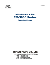
[Figure1.GTD-2000Tx(2W)Overview]
Gas
Sensor Module
(GSA860TX)
Main Board
(Transmitter)
VIN & 4-20mA
Analog
Signal Output
Display Board
(User Interface)
Transmitter enclosure
(GDH-1000)
Safety Controller
(PLC or DCS)
GTD-2000Tx-2w Gas Detector
Hazardous Area (Filed) Safe Area
3.1. Basic Specifications
ITEMS SPECIFICATION
Measuring Type Diffusion
Measuring Value Display Local Digital LCD Display
Measuring Method Electrochemical Cell
Detectible Gas Toxic Gas (Note 1)
Measuring Range 000.0 ~ 9999 (Note1)
Accuracy ≤±3%/FullRange
Zero Drift ≤2%/FullRange
Response Time
Depends on Sensor Module.
Refer to Sensor Specification or Contact in case for Special Gas.
Approvals Classification KCs: Ex d llC T6
Basic Interface Analog 4-20mA current interface
Option Rain Cover
Warranty
Transmitter 2Year
Sensor 1Year
3.2. Mechanical Specifications
ITEMS SPECIFICATION
Explosion-Proof Type Explosion-Proof Enclosure
Dimension 136(W)×166(H)×95(D)mm
WeightincludingSensor App. 1.5kg
Mounting Type Wallmount
Mounting Hole Ø7±0.1
Cable Inlet 3/4"PF(1/2"or3/4"NPT)
Body material
Transmitter Aluminum Alloy
Sensor Stainless Steel (STS316)
※Note1.Refertothemeasuredgaslistformeasuredgasesandtheirranges.Contactusforspecialgas.
GTD-2000Tx(2-wire) toxic gas detector has been developed to detect gas leaked from industrial sites and various toxic
gases generated from factories, gas storages, and manufacturing processes that produce or use toxic gases and to
prevent accidents in advance.
GTD-2000Tx(2W)toxicgasdetectorisinstalledinareaswithgasleakhazardsandcontinuouslymonitorsgasleak.It
displays measurements on LCD of the detector, converts and transmits data in DC 4~20 mA standard output signal. Also,
for DC 4~20 mA standard output, output signal transmission length between detector and receiver can be connected up
to2,500m.(WhenCableCVVSorCVVSB1.5sqandaboveisused.)
BodyofGTD-2000Tx(2W)ismadeofAluminumalloyandthegassensormoduleismadeofstainlesssteel.Itconsists
of a complete explosion-proof enclosure (Ex d IIC T6). This product can be installed in areas with combustible gas leak
andexplosionhazards.Ithasbuilt-inLCDonthedetectortodisplaygasleakstatusatinstalledsite.Itconsistsofdisplay
part that indicates measurements, terminal part that output measurements (DC 4~20 mA) externally, and a PCB board.
External configuration consists of detector part that monitors gas leak and cable inlets.
2. Conguration
1. Overview 3. Specications

www.gastron.com
08
_
09
GTD-2000Tx(2W)
Instruction Manual
[Figure2.GTD-2000Tx(2W)Components]
3. Specications 4. Name and Description of Each Part
3.3. Electrical Specifications (Standard Type)
ITEMS SPECIFICATION
Input Voltage(Standard)
※CustomersuppliedPSUmustmeet
requirements IEC1010-1 and CE
Marking requirements.
Absolute min:
Nominal:
Absolute max:
Ripple maximum allowed:
16V
24V
31V
1V pk-pk
Wattage
Max. wattage:
Max. current:
0.5W@+24VDC
22mA @+24 VDC
Analog output Current
0-20 mA (500 ohms max load)
Allreadings±0.2mA
Measured-value signal: 4mA(Zero) to 20mA(Full Scale)
Fault:
0-100%LEL:
100-109%LEL:
Over110%LEL:
Maintenance:
3mA
4mA - 20mA
21.6mA
20mA - 21.4mA
3.5mA
Analogoutputcurrentripple&noisemax ±20uA
Wiringrequirement Power CVVS or CVVSB with shield
Cable Connection Length Analog 2500m
EMC Protection: Complies with EN50270
No ITEMS SPECIFICATION
1 Detector Housing Body Protects PCB Board built in Sensor and Housing from external environmental change and shock.
2 Detector Housing Cover
It is assembled with Detector Housing Body.
Top surface is built with circular glass to enable monitoring of measurement displayed on LCD.
3 AMP PCB
Amplifies fine outputs generated from Sensor Element to transmit
a converted output in 4~20 mA DC standard. It sends data to display part.
4 Display PCB
Displays data sent from Main (Terminal) Transmitter PCB on LCD and
displays power status with a power lamp.
5 DIP Switch DIPSwitch(SW1)issetbasedonSensortype.
6 Sensor Terminal CN5isSensorConnectionTerminal.(Blue,Red,White)
7 Power LED Lamp lights on when power is supplied.
8 Function Key
Used during Parameter setting to enter the Program by contacting a magnet bar for 2 s and longer.
Used to enter data for setting.
3.4. Environmental Specifications
ITEMS SPECIFICATION
Operation Temperature
Transmitter -40to80℃
Sensor Refer to Sensor Specification
Storage Temperature
Transmitter -40to80℃
Sensor Refer to Sensor Specification
Operation Humidity
Transmitter 5to99%RH(Non-condensing)
Sensor Refer to Sensor Specification
Pressure Range 90 to 110KPa
Max. air velocity 6m/s
4.1. Components

www.gastron.com
10
_
11
No ITEMS SPECIFICATION
9 Reset Key
To cancel or return to the previous status during Parameter setting, use the Magnet-Bar and
touch once.
Each touch returns to the previous status by one unit.
10 (↑)Key
During conversion of mode or number, use the Magnet-Bar and touch once.
Each touch converts or increases displayed value by one unit.
11 (↓)Key
During conversion of mode or number, use the Magnet-Bar and touch once.
Each touch converts or decreases displayed value by one unit.
12 External Ground
It must be grounded to outside of detector for protection from external noise or strong electric
field.
13
Mount Hole
(ø7×2ea)
Hole to fix the gas detector on external wall or other installation sites.
14 Sensor
It is a site that detects actual gas leak. It converts the amount of gas leak into electrical signal and
transmits to the Main PCB.
15 Conduit Connection
It is supplied during installation work to supply power to detector part and inlet of measured
outputsignal.3/4"or1/2"PF,NPTispreparedforcableinlet.(DefaultisPF3/4")
16 Internal Ground
It must be grounded to inside of detector for protection from external noise or strong electric
field.
[Table1.GTD-2000Tx(2W)DescriptionofComponents]
GTD-2000Tx(2W)
Instruction Manual
5. Installation
It is prohibited for an individual, other than an approved user or a technician responsible for installation and repair from
the head office, to install a gas leak detector on site or open the cover of the installed gas leak detector and manipulate
it. This may cause serious loss of life and property from fire, explosion, and etc. In addition, please check whether there
is any remaining explosive gas or combustible material in the surroundings. Power must be turned off before performing
work.
[Figure4.MethodtodetachDisplayPart]
[Figure3.SlottedSetScrew]
4. Name and Description of Each Part
5.1. Detachment of Housing Cover
■Afterdetachingthecover,disassemblethedisplayparts
as below.
① Pushinleftandrightfixingringslocatedonfrontside
of LCD at the same time.
② Whilepushing,pullthedisplaypartstowardsthefront
to detach from gas detector body.
③ Afterdetachingthedisplayparts,theMainPCBis
installed at the bottom part of the detector body.
■<Warning-Donotopenwhenelecticalcurrentis
flowing>
■Turntheslottedsetscrew(M4x1ea)fixingthecover
part of main body 3~4 turns counter clockwise (ccw)
using a hex wrench (M2) then turn the cover of gas
leak detector ccw to detach the cover.
Whenthecoverisdetached,LCDappears.

www.gastron.com
12
_
13
5. Installation 5. Installation
GTD-2000Tx(2W)
Instruction Manual
[Table2.MainPCBKeyPartDescription]
5.2. Main PCB Configuration
■Afterdetachingthecover,theMainPCBterminallayoutappearsasshowninthefigurebelow.
No NAME DESCRIPTION
1 CN6 Program download Connector
2 CN2 Display Module Connector for Status Display
3 CN5 Sensor Connector
4 CN4 Program download Connector
5 VR2 Potentiometer to control ZERO output (Factory Setting)
6 VR1 Potentiometer to control SPAN output (Factory Setting)
7 SW1 Sensor Configuration Switch1 (Factory Setting)
8 SW2 Sensor Configuration Switch2 (Factory Setting)
9 CN1 Power&OutputSignalTerminal
[Figure5.MainPCBKeyLayout]
[Figure6.CN1TerminalConfiguration]
■UseCVVSorCVVSB2.0sq↑ShieldCableforterminalconfiguration.
[Table3.CN1TerminalDetailedDescription]
NO PIN NAME DESCRIPTION
1 +V +24V/POWER(+)
2 -V 4~20mA Source Out
3 ET EARTH
5.3. Power and Signal Terminal Configuration
■<Warning-Turnoffpowerbeforeconnectingpowerterminal>
■Afterdisassemblingdisplayparts,thereisaterminalblockintheMainPCBasshowninthefigurebelow.
Holding it with hands and pulling towards ceiling detaches it from the Main PCB.
■Loosen5terminalfixingscrewslocatedattoppartofdetachedterminalblockCN8(VIS,+,mA,-,ETH)Connector
byturningccwusingaΘdriver.ConnectDC18~24Vpowerto+,and-thenconnectsignalcabletomA.Tighten
5 terminal fixing screws clockwise (cw) so that terminal does not leave the track then insert Main PCB as the same
condition before disassembly.

www.gastron.com
14
_
15
GTD-2000Tx(2W)
Instruction Manual
5. Installation 5. Installation
5.4. Method to Connect to External Control Unit
■Connect18V~31VDCoperationpowertoCN1(+,mA,-,ET)ConnectionTerminalofthegasdetectorthen
connect a device that can receive 4~20 mA signals to mA.
[Figure7.MethodtoconnectExternalControlUnit]
5.5. Installation Cable Length
■ThemaximumlengthbetweenGTD-2000Tx(2W)andpowersupplyisdecidedbywirespecification.
■Max.InstallationLength=VMAXDROP÷IMAX÷WIRER/m÷2
·VMAXDROP:MaximumPowerLoopVoltageDrop(=PowerSupplyvoltage-minoperatingvoltage)
·IMAX:Max.CurrentofGTD-2000Tx(2W)
·WIRER/m:Theresistanceofthewire(ohms/metervalueavailableinwiremanufacturer'sspecificationdatasheet)
■Exampleofinstallationlengthsusing24Vpowersupplyand16AWGisasfollows.
·GTD-2000Tx(2W)minimumoperatingvoltage=16VDC
·VMAXDROP=24-16-5.5=2.5V
·IMAX=0.022A(22mA)
·2.5÷0.022÷0.01318÷2=4,310.9m≒4310m
[Figure7.CalculationofGTD-2000Tx(2W)InstallationCableLength]
■Powercableinstallationforeachcabletypeisasshowninthetablebelow.
[Table4.GTD-2000Tx(2W)PowerCableInstallationLength]
AWG mm2 COPPER RESISTANCE(ohms/m) METERS
12 3.31 0.00521 10905
14 2.08 0.00828 6862
16 1.31 0.01318 4310
18 0.82 0.02095 2712
20 0.518 0.0333 1706

www.gastron.com
16
_
17
GTD-2000Tx(2W)
Instruction Manual
6.1. Initial Operation Status (Power On)
■AfterwiringtopowerterminalatthetopofMainPCBboardthensupplypower,thefollowingcontentsare
displayedonLCD.Approx.30minofstabilizationoftimeisneededfromtheinitialsupplyofoperationpowerandit
startstooperatenormallyaftersufficientstabilization.
- Displays Program Version
-Afterrunning"SELFTEST"for30secthenconvertstoMeasuringMode.
-During"SELFTEST",statusLEDblinksontheMainBoard.Aftercompletionof"SELFTEST",statusLED
- lights on.
-However,whenMembraporO2isused,"SELFTEST"persistsuntilthesensorstabilizes.
- Contacting"RESET"keyreturnstoMeasuringMode.
- Displays the current measurement.
-Whenavalueequalorgreaterthan10%ofHighScalevalueisinputted,"OUr(over)"isdisplayedonLCD.
-When%LELvaluebelowzeroisequalorlessthan-10%,"Und(under)"isdisplayedonLCD.
- (Optional - Refer to Page 20)
6.2. Measuring Mode
■Afterpoweron,whenthereisnoerrorfrom"SELFTEST",itautomaticallyentersMeasuringMode.
6.3. Operation Flow
LEVEL1
LEVEL2
DEFAULT
NAME PARAMETER
(Decimal-Point) 100,10.0,1.00,0.100 100
(High-Scale) 1~1999 100
(Gas Function Type) Ty1,Ty2,Ty3,Ty4 Ty1
(Pass-Word) 0~99 --
(Version) XXX XXX
(End) - -
(Zero-Calibration) NO , YES NO
( 0 ) - -
(Good) - -
( 0 ) - -
(Span-Calibration) NO , YES NO
( 50 ) - -
(Good) - -
( 50 ) -
Sensor Mode Factory Mode
Option Mode Factory Mode
System Mode Factory Mode
Program Mode
Calibration Mode
■Afterpoweron,itpassesself-diagnosticprocessthenentersMeasuringMode.Here,byoperatingfrontkeys,you
can go to internal System Mode.
■TimeoutforLevel1andLevel2are10sec.Itissetto1hforLevel2CalibrationandTestMode.
■When"RESET:keycontactsatProgramModeScreen,itreturnstoMeasuringMode.When"RESET"keycontactsat
each Program Setting Screen, it returns to the parent step.
6. Detector Operation Flow 6. Detector Operation Flow

www.gastron.com
18
_
19
GTD-2000Tx(2W)
Instruction Manual
7. System Mode 7. System Mode
-Contacting"FUNC"keywiththeMagnet-barfor2secorlongerinMeasuringModeentersPasswordmode.
-Entera2-digitpasswordusing"↑"or"↓"keythencontact"FUNC"keytoenterProgramMode.
-Contact"↑"or"↓"keytoselect"CalibrationMode".
-Contact"FUNC"keywhen"CAL"isdisplayedtoenterCalibrationMode.
-Contact"RESET"keytoreturntoMeasuringMode.
-Contact"↑"or"↓"keytoachieveZ-C(Zero-Calibration)thencontact"FUNC"keytoenterthenextstep.
-Contact"↑"or"↓"keytoachieve[YES]thencontact"FUNC"keytoenterZeroCalibration.(Default"no")
- Mode that performs Zero Calibration and measurement is displayed.
-Usingacalibrationtool,injectcleanairor100%nitrogenintothesensorataflowrateof500mL/min
- for1min.Contact"FUNC"keywhenmeasurementisstabilizedtoautomaticallyperformZeroCalibration.
-Whenzerocalibrationissuccessful,"god(good)"isdisplayedonLCDdisplayfor2sec.
-Whenzerocalibrationisnotsuccessful,"FAI(Fail)"isdisplayedfor2secanditchangesto"CalibrationData".
-Contact"RESET"keytoreturnto"Calibration".
- It is a mode to display measurement after calibration and checks whether calibration is successful after
- performing auto calibration.
-Contacting"FUNC"keyreturnsto"CalibrationMode".
-Contact"↑"or"↓"keytoachieveS-C(Span-Calibration)thencontact"FUNC"keytoenterthenextstep
-Contact"↑"or"↓"keytoachieve[YES]thencontact"FUNC"keytoenterSpanCalibration.(Default"no")
-Usingacalibrationtool,injectstandardgastothesensor.Whenitisstabilized,contact"FUNC"key.
-Using"↑"or"↓"key,setstandardgasvaluethencontact"FUNC"key.
7.1. PROGRAM MODE
PASSWORD
[**]
-Contacting"FUNC"keywiththeMagnet-barfor2secorlongerinMeasuringModeentersPasswordmode.
-AftersettingPasswordusing"↑"or"↓"key,contact"FUNC"key.
PROGRAM
MODE
- If password is correct, it enters Program mode.
-Bycontacting"↑"or"↓"key,modechangesindefinedorder.
- ( PROGRAM -> CALIABRA. -> ALARM -> SENSOR -> MAINTEN. -> DEVICE -> VERSION -> TEST )
GAS TYPE
[ DEFIN. ]
-Modethatsetsgasnametypeandcontacting"↑"or"↓"keychangesgastype.(DEFIN./USER)
- DEFIN. Is acronym for Define and is selected when using built-in setting of gas name.
- USER is selected when the user directly sets a gas name.
-Whenadesiredgastypeisdisplayed,contact"FUNC"keytosetthegasnameandenterProgramMode.
GAS SEL
[ COMB. ]
-Modethatsetsgasnameandcontacting"↑"or"↓"keychangesgasname.
-WhengastypeissettoDEFIN.,built-ingasnamescanbeselectedforuse.WhenitissettoUSER,
- the user shall set gas name using 5 character for use. Characters allowed for use are number, capital
- Alphabet,space,andperiod.Whenpositionismovedbysettingcharacters,acursorinblackboxshape
- appears as shown in the figure on left.
USER GAS
[■ SER ]
UNIT SEL
[ %LEL ]
-Modethatsetsgasmeasuringunitandcontacting"↑"or"↓"keychangesgasmeasuringunit.
- (%/%LEL/PPM/PPB).
-Whenadesiredgasmeasuringunitisdisplayed,contact"FUNC"keytosettheunitandenterProgram
- Mode.
D-POINT
[ 100]
-Modethatchangesdecimalplaceandcontacting"↑"or"↓"keychangesdecimalplace.
- (0.100/1.00/10.0/100)
-Whenadesireddecimalplaceisdisplayed,contact"FUNC"keytosetthedecimalplaceandenterthe
- next Program Mode.
HIGH SCL
[ 100]
-Modethatsetshighscalevaluethatshouldbedisplayedforfullrange.Contacting"↑"or"↓"key
- increases or decreases the scale value. (1 ~ 10000)
-Whenadesiredhighscaleisdisplayed,contact"FUNC"keytosetthehighscalevalueandenterthe
- next Program Mode.
PASSWORD
[00]
- It is password setting mode. This password is checked when entering Program Mode.
-Setusing"↑"or"↓"keythencontact"FUNC"keytosetthepasswordandenterthenextProgramMode.
7.2. CALIBRATION MODE
■Duetocharacteristicsofthegasdetector,minimum30minofstabilizationtimeisrequiredandmaintenance
condition may change depending on site condition.

www.gastron.com
20
_
21
GTD-2000Tx(2W)
Instruction Manual
7. System Mode
-Whenspancalibrationissuccessful,"god(good)"isdisplayedonLCDdisplayfor2sec.
-Whenspancalibrationisnotsuccessful,"FAI(Fail)"isdisplayedfor2secanditchangesto"Calibration
- DataMode".
-Contact"RESET"keytoreturnto"CalibrationMode".
- It is a mode to display measurement after calibration and checks whether calibration is successful after
- performing auto calibration.
-Contacting"FUNC"keyreturnsto"CalibrationMode".
8. Drawings and Dimensions
[Figure8.GTD-2000Tx(2W)Drawing]

www.gastron.com
22
_
23
GTD-2000Tx(2W)
Instruction Manual
9. Precautions before Installation 9. Precautions before Installation
9.1. Selecting a Place for Installation (Occupational Health & Safety Act Data)
A gas leak detector alarm shall be installed in the following places.
■
Around chemical equipment and accessories that have concerns of gas leak. This includes compressors, valves, reactors,
pipe joints, etc. installed inside and outside of a building that handle combustible and toxic materials.
■Placesthatareeasierforgasestostaysuchasareasaroundmanufacturingfacilitieswithignitionsourceslikeheating
furnace, etc,
■Areasaroundequipmentforfillingcombustibleandtoxicmaterials.
■Substations,panelrooms,controlrooms,andetc.locatedwithinexplosivearea.
■Otherareasthatareeasierforgasestostay.
9.2. Selecting a Site for Installation (High-Pressure Gas Safety Control Act Data)
Gas detector of gas leak detector alarm must be installed as close to the areas with concerns of gas leakage as possible.
However, for areas where direct gas leakage is not expected but are easier for leaked gas to stay, the detector must be
installed at the point 1 of the following.
■ Gasleakdetectoralarminstalledoutsideabuildingshallbeinstalledatpointswheregasislikelytostayinconsideration
to wind direction, wind speed, specific gravity of gas, etc.
■Gasleakdetectoralarminstalledinsideabuildingshallbeinstallednearthefloorwhenthespecificgravityofgasis
heavier than air and near ventilation of ceiling when it is lighter than air.
■Alarmforgasleakdetectoralarmmustbeinstalledatsiteswherethegasdetectorisinstalledandworkersarepresent.
9.3. Precautions during Installation
Avoid areas with electrical barriers such as rain water, etc. It is recommended to be installed in areas that are easier to
work in since regular maintenance is needed. Avoid areas with vibration or shock since they can affect output values.
Sensor part must be installed towards the direction of gravity.
■Thisequipmenthasexplosion-proofconstructionforinternalpressureandbelongstoGROUPIIforgasandvaporin
generalworksitesandchemicalplants.ItcanbeusedinZONE1(ONE)andZONE2(TWO)hazardoussites.
■Allowabletemperatureis85Corbelow,whichcorrespondstoT6.
■Surroundingtemperatureshallbeinarangeof-40to80°C(forMainbody.Forsensor,refertoeachsensormanual.)
■InstallationHeight:1,000Mbelowsealevel
■RelativeHumidity:5%~99%(Non-condensing)
■InstallationSite:IndoorandOutdoor
■ExplosionIgnitionGroupforTargetGasorVapor:ExdIICT6
■
During wiring work, use explosion-proof cable gland at cable inlet or tightly seal cable conduit during metal cable wiring
construction to prevent spread of flames in case of explosion or movement of gas, etc. through the cable conduit within
50 mm. All materials including materials used for sealing of unused inlets must have safety certificates!
■Whenconnectingtheequipmentwithcable,screwthreadmustbetightened5threadsormore.
■
Workinconditionssatisfyingother[StandardsforSelection,Installation,andMaintenance,etc.ofExplosion-proofElectric
MachineandEquipmentWiring,etc.atWorkSite]
■
All materials used for cable inlet such as cable gland and sealing fitting, etc. and used as sealing unused inlets must pass
the verification!
[Figure9.High-PressurePackingType] [Figure10.YSealingCompound]
Cable Cable
Inside
Inside
Outside
Outside
Lead-in unit connector
Lead-in unit connector
Charging compound
Cable-fixing device
Pipe for piping
Cable-fixing device
Sealing ring
Sealing
ring
Connector
Pipe for piping
Compressed
element
Connector for fixing
compressed element

www.gastron.com
24
_
25
GTD-2000Tx(2W)
Instruction Manual
VERSION CONTENTS DATE
0.0 * Manual Initial Revision 2012.04.17
1.0 * Corrected Typos 2012.04.20
2.0 * Changed consumed current 2013.01.21
3.0 * Changed Font 2013.02.21
4.0 * Added Program Mode Function. 2014.06.08
5.0 * Added O2 function 2014.10.24
6.0 * Separated Factory mode manual 2016.09.28
7.0 *ChangedExplosion-proofEquipmentCableEntryInstallationRegulation45cm→50mm 2017.01.20
10. Revision History
/