Page is loading ...

INSTALLATION AND OPERATING INSTRUCTIONS
Astro Express 2 - Hot Water Delivery System
TYPICAL APPLICATIONS
The Armstrong Astro Express 2 hot water delivery system ensures that users have hot
water at the tap when you need it, while helping to conserve water. It’s easy to install,
and does not require special return piping to the water heater.
Equipped with a high performance circulator and adjustable flowrate injection valve,
the Astro Express 2 system is a “one-size-fits-all” solution for virtually any residential
installation. The Astro Express 2 is the ideal solution for existing home retrofit where
recirculation system return line installation is impractical, or new home construction
where dedicated hot water return line installation is cost prohibitive.
HOW IT WORKS
Armstrong Astro Express 2 hot water delivery systems consist of a circulator for water
heater mounting, and a valve for under-sink mounting. In operation, the timer activated
circulator creates differential pressure across the Astro Express LF valve. When the water
at the hot water faucet cools below the Astro Express LF valve low temperature setpoint,
the valve opens, allowing the cooled water to be injected into the cold water line. When
the water reaches the valve high temperature setpoint, the valve closes. The valve is
equipped with a pressure independent flowrate adjustment to maintain the desired
temperature balance. Additionally, the valve is equipped with a check valve to prevent
cold water backflow when the hot water faucet is opened.
INSTALLATION
WARNING:
Installation should only be completed by qualified personnel, in accordance with all applicable codes, and following
generally accepted installation practices.
Ensure the hot and cold water supply is turned off before installation, to avoid personal injury or damage to
property.
Read and understand these instructions thoroughly before beginning the installation.
CAUTION:
Prior to installation flush all piping of any foreign material to prevent pump blockage and prevent damage.
FILE NO.: 10.817
DATE: Apr. 4, 2011
SUPERSEDES: 10.817
DATE: Feb. 24, 2010
Page 1 of 5

PROCEDURE
1. Timer installation and wiring.
WARNING:
Electrical shock hazard - Verify that the electrical rating of the device matches the values shown on the
nameplate of the circulator.
All electrical work should be performed by a qualified electrician in accordance with the latest edition of the
National Electric Code, local codes and regulations. Failure to follow these instructions could result in serious
injury, death and/or property damage.
Not
e: Numerical component designations included in Steps “a” through “j” refer to circulator and timer
components shown in Fig. 1.
a. Unfasten the mounting screw (4A) and remove the terminal box cover (3).
b. Unfasten the mounting screw (4B) on the timer box cover (10) and detach it from the base (8).
c. Remove the original conductor (7A) from the circulator terminal box (2)
d. Fasten the connection adaptor (7B) to the circulator terminal box (2)
e. Fasten the threaded fitting (6) to the connection adaptor (7B)
f. Fasten the lock nut (5A) on the end of the threaded fitting (6) and insert the timer box (8)
g. Fasten the lock nut (5B) onto the end of the threaded fitting (6) so the timer box (8) is in between and
securely attached.
h. Connect timer lead wires (black, white and green) to the terminal box (as shown in Fig. 2).
i. Re-attach the timer box cover (10) using the mounting screw (4B). Insure that all lead wires are inside the
timer assembly.
j. Close the terminal box cover (3) by fastening the mounting screw (4A).
TIMER
WHITE
WHITE
WHITE
GREEN
GREEN
BLACK
BLACK
BLACK
BLACK
BLACK
G
Green Ground
Screw in timer box
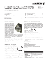
Fig. 1 Astro 2 Series circulator and 24-Hour Timer assembly drawing Fig. 2 Astro 2 Series circulator and 24-Hour Timer wiring diagram
2.
To mount the Astro Express 2 circulator:
a) Turn off water supply. (If necessary, drain the hot water distribution pipes and partially empty the
water heater.)
b) Disconnect the hot water distribution pipe from the water heater outlet.
c) Connect the Astro Express 2 circulator inlet to the water heater outlet nipple.
d) Connect the distribution pipe to the circulator outlet.
Page 2 of 5

3.
Ensure the following conditions are met:
a) The circulator shaft is horizontal.
b) The clock/timer face is accessible for viewing and adjustment.
c) The direction of water flow matches the arrow on the circulator casing.
d) The piping is sufficiently rigid to support the system in operation.
e) Neither the clock/timer nor black terminal box is under the circulator.
4. If the arrow on the circulator casing is not pointing away from the hot water heater,
see ROTATING THE CIRCULATOR CASING.
5. To mount the Astro Express LF valve:
a) Select the faucet to be controlled, typically the furthest faucet from the hot water
heater. (For multi-branch hot water piping runs, a valve may be required at the
end of each branch for maximum effectiveness.)
b)
Disconnect the hot and cold supply pipes from the faucet.
c) Connect the hot and cold water supply to the Astro Express LF valve 1/2"
threaded inlets. (Stainless steel flex hose recommended.)
d) Connect the hot and cold Astro Express LF valve 3/8" threaded outlets to the
faucet. (Stainless steel flex hose recommended.)
e) Secure the valve to the wall under the sink, using the plastic wall anchor and
screw.
6. Check the installation for leaks:
a) Ensure the faucet is closed.
b) Turn on the water supply.
c) Open the hot and cold water supply valves.
d) Open the faucet hot and cold taps to purge all air from the system. Close the faucet.
e) Inspect the circulator and valve connections for leakage. If a leak exists, close hot and cold supply valves until
leaks are corrected.
7. To connect power to the circulator:
a) Verify that the timer’s manual over-ride switch is in the “OFF” position.
b) Plug the power cord into a standard 115 Vac household electrical receptacle.
c) To perform and initial system test, see OPERATION.
ROTATING THE CIRCULATOR CASING
Prior to connecting the system to the hot water piping, if alternate orientation of either the
circulator discharge or clock timer is required, proceed as follows:
1. Remove the four hex socket head screws that hold the casing to the circulator.
2. Gently pull the casing from the circulator body, taking care not to damage the gasket or
impeller.
3. Rotate the casing as required to meet circulator discharge and clock timer orientation
requirements.
4. Tighten the four hex socket head screws evenly; ensuring the gasket seals the mating
surfaces.
5. To verify the circulator shaft still spins freely:
a) Remove the plug from the end of circulator with a slotted screwdriver.
b) Insert the screwdriver in the slot in the end of the shaft.
c) Ensure the shaft turns freely and smoothly in both directions.
d) Replace the plug and gently tighten.
Page 3 of 5

OPERATION
CAUTION: Never operate the system “dry” or permanent damage may occur to the circulator. Never shut off the
water supply or restrict flow in any way while the circulator is operating.
1. Verify water is present at the circulator.
2. Verify the power cord is plugged into an appropriate household electrical receptacle.
3. To continuously run the circulator or test for initial operation, set the manual override switch to the “ON” position
and verify the circulator operates smoothly and quietly.
4. To prevent circulator operation, such as for extended periods that the residence will be vacated, set the manual
over ride switch to the “OFF” position.
5. For normal automatic operation, set the clock/timer as required and move the manual override switch to the
“AUTO” position.
Manual Override
Switch Positions
OFF
ON
AUTO
SETTING THE CLOCK/TIMER
1. Rotate the dial in a clockwise direction until both the time shown,
and the appropriate AM or PM indicator, correspond to the current
time of day. (This adjustment is required for initial operation,
following a power interruption, to adjust for daylight savings time,
or for periodic time correction.)
2.
Remove the clear plastic cover from the dial.
3. The outer ring of the dial has an adjustable tab for each 15 minute
time interval of a 24 hour day. To enable circulator operation for a
specific time interval, slide the corresponding interval tab to the
outer position. All tabs positioned toward the center of the dial
disable circulator operation for those time intervals.
4.
Verify the manual override switch is in the “AUTO” position.
5. Replace the clear plastic cover on the dial.
Dial
Interval Tabs
(15 minutes each)
For maximum
energy savings, set the timer to:
a) Activate the circulator at least ½ hour before initial hot water
demand for the day is anticipated.
b) Deactivate the circulator when the anticipated hot water
demand for the day ends.
SETTING THE VALVE
The Astro Express LF valve is factory set to suit most applications. The valve may be easily
adjusted to suit application conditions and personal preferences.
1. To increase the water temperature at the hot-water tap, turn the flowrate adjustment counter
clock-wise one or two increments.
2. To decrease the water temperature at the cold-water tap, turn the flowrate adjustment
clock-wise one or two increments.
3. To completely stop flow through the valve, turn the valve completely closed by turning the
flowrate adjustment fully clockwise.
If necessary to achieve the desired water temperature control, set the circulator timer to cycle
the circulator on/off during the anticipated hot water demand period, in combination with valve
adjustment.
Allow ample time (at least several hours) after valve or timer adjustment, for the system
temperature to stabilize, prior to evaluating the result of the adjustment.
Manual Override
Current Time
AM/PM Indicators
Flowrate
A
d
j
ustment Screw
Page 4 of 5

TECHNICAL DATA
ASTRO EXPRESS 2 CIRCULATOR Astro 220SSU
Max. Power Consumption 43W, 0.36A
Max. Head 4.5 ft (1.4 m)
Max. Flow 9.5 GPM (0.60 L/s)
Default Operating Speed Speed 3
Power Requirements 120 Vac, 60 Hz
Power Connection 5.0 ft (1.5 m) power cord, molded duplex plug with ground
Environment Indoor use only
Max. Working Pressure 150 psi (1034 kPa)
Ambient Temperature 39°F (4°C) to 104°F (40°)
Max. Water Temperature 230°F (110°C)
Clock Timer 12-hour analog clock with AM/PM indication
Timer Settings Individual toggles for each 15 minute interval over 24 hours
Manual Override 3 position slide switch, on/off/auto
Pump Casing Stainless steel with 1-1/4" NPSM union threads
Impeller Polyether Imide (PEI)
Shaft Ceramic
Bearings / Seal Ceramic
Union Tailpieces Brass, 3/4" FPT (two) and 3/4" MPT (one)
Union Gaskets EPDM (two)
Approvals
listed
ASTRO EXPRESS LF VALVE
Housing Forged Eco brass* with Noryl cap
Internal Components Stainless steel and plastic with EPDM o-rings
Connections Threaded, 1/2" hot & cold inlets, 3/8" hot & cold outlets
Environment Indoor use only
Flowrate Adjustment 0 – 100%, multi-turn slotted screw
Max. Working Pressure 100 psi (689 kPa)
Max. Water Temperature 140°F (60°C)
Mounting Plastic wall anchor with screw
*Complies with section 116875 at the California Health and Safety Code and Vermont Act 193 (Lead content of
wetted surface is 0.25% or less.)
REPLACEMENT PARTS
PART DESCRIPTION ITEM NUMBER
Part Description Item Number
Astro 220SSU-T 110223-244
3/4" FPT Union Lead Free* Hardware Kit 810120-324
3/4" MPT Union Lead Free* Tailpiece 810120-346
24-hour Timer 810123-130
Timer Cover 110123-031
Astro Express LF Valve 561100 LF-001
S. A. Armstrong Limited Armstrong Pumps Inc. Armstrong Holden Brooke Pullen
23 Bertrand Avenue 93 East Avenue Wenlock Way
Toronto, Ontario North Tonawanda, New York Manchester
Canada, M1L 2P3 U.S.A. 14120-6594 United Kingdom, M12 5JL
T: 416-755-2291 T: 716-693-8813 T: +44 (0) 161 223 2223
F: 416-759-9101 F: 716-693-8970 F: +44 (0) 161 220 9660
© S.A. Armstrong Limited 2011
Page 5 of 5
For Armstrong locations worldwide, please visit www.armstrongintegrated.com
/