Page is loading ...

VLH-3000A
30 Watt Loud Hailer
Owner’s Manual
PADIMIC

TABLE OF CONTENTS
1. GENERAL INFORMATION ............................................................... 1
2. PACKING LIST .................................................................................2
3. OPTIONS ..........................................................................................2
4. INSTALLATION .................................................................................3
4.1 Optional MMB-84 Flush Mount Installation ...........................3
4.2 Electrical Installation ............................................................... 4
5. CONTROLS AND SWITCHES ..........................................................6
6. OPERATION .....................................................................................8
6.1 Switching Power On/Off .......................................................... 8
6.2 Hail/Listen-Back ....................................................................... 8
6.3 Intercom ....................................................................................8
6.4 Automatic Signaling ................................................................9
7. FOG ALERT TONE FREQUENCY .................................................12
8. MAINTENANCE .............................................................................. 13
8.1 Replacement Parts ................................................................13
8.2 Factory Service ......................................................................13
8.3 Troubleshooting Chart ..........................................................14
9. WARRANTY .................................................................................... 16
10. SPECIFICATIONS .........................................................................18
11. FCC NOTICE ................................................................................. 19

Page 1
VLH-3000A
1. GENERAL INFORMATION
The STANDARD HORIZON VLH-3000A is a marine Loud Hailer that op-
erates as a multifunction unit. It has three modes:
m
Hail/Listen-Back
m
Intercom
m
Automatic Signalling
In the Hail/Listen-Back mode, the Loud Hailer can send amplied audio
signals to a PA horn and then listen back for signals coming in from the
PA horn.
In the Intercom mode, the Load Hailer can have private conversations
with up to two MLS-300i intercom stations.
In the Automatic Signaling mode, the Loud Hailer can send different
kinds of signals used mostly to alert nearby vessels to the presence and
approximate position, and to indicate the vessel’s status or maneuver-
ability limitation.
Your Loud Hailer requires 13.8 VDC (±20 %) power input. The VLH-
3000A maximum PA speaker output is 30W.
ON-LINE WARRANTY REGISTRATION
Please visit www.standardhorizon.com to register the VLH-3000A
Loud Hailer. It should be noted that visiting the Web site from time
to time maybe beneficial to you, as new products are released
they will appear on the STANDARD HORIZON Web site.
PRODUCT SUPPORT INQUIRIES
If you have any questions or comments regarding the use of the
VLH-3000A, you can visit the STANDARD HORIZON Web site to
send an E-Mail or contact the Product Support team at 800-767-
2450 M-F 8AM-5PM PST.

VLH-3000A
Page 2
2. PACKING LIST
When the package containing the Loud Hailer is first opened, please
checkit for the following contents:
VLH-3000A Loud Hailer (with Microphone)
Mounting Bracket (with attaching hardware and hanger kit)
Owner’s Manual
Power Cord
Dust Cover
3. OPTIONS
MMB-84 Flush mount bracket
MLS-300i Loud Hailer Intercom Speaker (with CALL button)
MLS-300 External Speaker
MLS-310 External Speaker (with 10 W amplier)
220SW 4.5” Round PA/Hailing horn
240SW 5” x 8” Rectangular PA/Hailing horn

Page 3
VLH-3000A
4. INSTALLATION
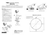
4.1 Optional MMB-84 Flush Mount Installation
1. To assist in ush mounting, a template has been included. Use this
template to nd the mounting location.
2. Use the template to mark the location where the rectangular hole is to
be cut. Conrm the space behind the dash or panel is deep enough to
accommodate the VLH-3000A (at least 4.5 inches or 11.5 cm deep).
There should be at least 1/2 inch (1.3 cm) between the VLH-3000A’s
heatsink and any wiring, cables or structures.
3. Cut out the rectangular hole and insert the VLH-3000A.
4. Fasten the brackets to the sides of the VLH-3000A with the lock
washer nut combination; so that the mounting screw base faces the
mounting surface (see Figure 1).
5. Turn the adjusting screw to adjust the tension so that the VLH-3000A
is tight against the mounting surface.
Bracket
Adjusting Screw
Lock-washer nut combination
Figure 1. MMB-84 Flush Mount Installation

VLH-3000A
Page 4
4.2 Electrical Installation
The rear panel of the VLH-3000A contains:
A DC Power Cord
A terminal strip for the External Speaker, two PA Horns, and two MLS-
300i Intercom Speakers.
Refer to Figure 2 and complete the following steps for the electrical in-
stallation.
POSITIVE
POSITIVE
NEGATIVE
NEGATIVE
YELLOW
YELLOW
WHITE
WHITE
WHITE
BLACK
WHITE
BLACK
BLACK
BLACK
External Speaker
Intercom Speaker
Intercom Speaker
PA Horn
PA Horn
Figure 2. Electrical Connections
NOTE
The terminal strip is not waterproof. Care needs to be taken when
installing so it is not directly exposed to the elements.

Page 5
VLH-3000A
1. Use the supplied Power Cord assembly for power connection. Con-
nect the red wire to the “Positive (+)” terminal, and the black wire to
the “Negative (–)” terminal of the power source.
CAUTION
Reverse polarity connections will damage the VLH-3000A.
2. Use #22 AWG (or larger) stranded, plastic-jacketed wire to connect
the PA Horns (“FWD” and “AFT” terminals) and Intercom Speakers
(“IC1” and “IC2” terminals).
3. An external 4-Ohm 6 W speaker may be connected (“EXT SP” termi-
nal), if desired.
4. For the PA Horn, it is recommended that a 4-Ohm 30 W horn speaker
be used. Also note that an 8-Ohm speaker may be used, but the loud-
ness will be reduced.
5. The VLH-3000A can use the optional MLS-300i Intercom Speaker.
This is connected to any of the Intercom terminals (“IC1” or “IC2”).
6. See Detail “A” in Figure 2, If a 2-wire speaker (such as a MLS-300
External Speaker) is connected to the Intercom terminals (“IC1” or
“IC2”), the positive wire should be connected to the center terminal
and negative wire should be connected to the left-hand terminal. Do
not connect the any wire to the right-hand terminal! If you connect one
of the wires of a 2-wire speaker to a right-hand terminal, the speaker
will beep continuously when turned on.
7. Put the supplied Protection Cover to the terminals to avoid a short cir-
cuit.

VLH-3000A
Page 6
5. CONTROLS AND SWITCHES
PADIMIC
LISTEN/PWR Knob
Turns the VLH-3000A on and off as well as adjusts the volume level
of the built-in speaker or external speaker in the LISTEN-BACK
mode.
AUTOMATIC SIGNALING Buttons
IC Knob
Adjusts the volume level of the Intercom Speaker in the INTERCOM
mode.
DIM Knob
Adjusts the display/keypad illumination for a comfortable brightness
level.
PA Knob
Adjusts the PA horn level in the HAIL or AUTOMATIC SIGNALING
mode.

Page 7
VLH-3000A
KEYBOARD
IC 1 - Activates the Intercom Speaker 1.
IC 2 - Activates the Intercom Speaker 2.
PA - Activates the PA horn.
FWD - Activates the Forward (Front) PA horn.
BOTH - Activates the both Forward (Front) and Aft (Rear) PA horns.
AFT - Activates the Aft (Rear) PA horn.
DISPLAY
- Indicates the Forward (Front) PA horn is selected.
- Indicates the Aft (Rear) PA horn is selected.
- Steady: Indicates Intercom Speaker 1 is selected.
Blink: Intercom 1 is calling the VLH-3000A.
- Steady: Indicates Intercom Speaker 2 is selected.
Blink: Intercom 2 is calling the VLH-3000A.
- Indicates the PA horn is selected
INTERNAL SPEAKER
Provides audio from intercom speakers or PA Horn.
INTERCOM Buttons
IC 1 - Activates the Intercom
Speaker 1.
IC 2 - Activates the Intercom
Speaker 2.
PTT Button
Activates the microphone.
MICROPHONE
Speak into the Mic while the PTT
button is press to transmit audio
to the PA horn or the Intercom
Speaker.
CALL Button
Used only when a Intercom Speaker is connected to IC1 or IC2.
When pressed produces a beep in the connected Intercom Speaker.

VLH-3000A
Page 8
6. OPERATION
This section contains operating instructions for the VLH-3000A.
6.1 Switching Power On/Off
1. Rotate the LISTEN/PWR knob clockwise to turn on the VLH-3000A.
2. To turn the VLH-3000A off, turn the LISTEN/PWR knob fully counter-
clock-wise.
6.2 Hail/Listen-Back
1. Press the PA button to activate the PA horn, then select the output PA
horn by pressing the FWD, BOTH, or AFT button.
2. Adjust the LISTEN/PWR knob to approximately 10 o’clock position, if
necessary turn clockwise to increase the internal (or external speaker
when connected) speaker volume.
3. Adjust the PA knob to approximately 10 o’clock position.
4. Press the microphone PTT button, then speak clearly with your mouth
about one inch (2.5 cm) from the microphone. Rotate the PA knob
with the PTT button pressed to adjust the PA horn output level. The
PA horn output level can be set from 0 to 30 watts.
5. Release the microphone PTT button. The PA horn will automatically
act as a microphone and the incoming audio signal will be heard from
the built-in or external VLH-3000A speaker. This is called Listen-Back.
6. Rotate the IC knob to increase or decrease the Listen-Back volume.
6.3 Intercom
To use the Intercom feature of the VLH-3000A, optional Intercom Speak-
er are necessary. The following are available from your Dealer:
MLS-300i - Intercom Speaker with PTA (Push To Alert)
1. To activate the Intercom Speaker(s), press the following keys:
IC1 - to activate Intercom Speaker 1
IC2 - to activate Intercom Speaker 2
2. Make sure the VLH-3000A is in the HAIL mode, and press the micro-
phone PTT button. Speak clearly with your mouth about one inch (2.5
cm) from the microphone.
3. To use the LISTEN-BACK mode, release the microphone PTT button.
The activated Intercom Speaker will automatically act as a micro-
phone and the incoming audio signal will be heard from the built-in/
external VLH-3000A speaker.

Page 9
VLH-3000A
4. Rotate the IC knob to increase or decrease the Listen-Back volume.
5. PTA (Push To Alert) feature: If the VLH-3000A in any other mode, the
Intercom Speakers can alert the VLH-3000A by pressing the PTA but-
ton on the MLS-300i. The VLH-3000A will produce a beep to indicate
a call from Intercom Station 1 of 2. At same time, “
” or “ ” icon
will blink. Press the corresponding intercom key to activate the Inter-
com Speaker. If the calling intercom speaker is already activated, the
icon will light continuously.
6. Adjust the volume of the internal/external speaker by rotating the LIS-
TEN/PWR knob.
6.4 Automatic Signaling
Automatic Signaling may be transmitted through the forward, aft or both
PA horns.
1. Select the PA horn to be used by pressing the FWD, BOTH, or AFT
button.
2. Press the one of the AUTOMATIC SIGNALING button to send the
de-sired signal to the selected PA horn:
Fog Horn Signaling
UNWY (Underway): Sends one 5 second blasts ever 2 minutes.
STOP: Sends two 5 second blasts (separated by 2 sec-
onds)ever 2 minutes.
SAIL: Sends one 5 second blasts followed by two 1
second blasts (separated by 2 seconds) ever 2
minutes.
TOW: Sends one 5 second blasts followed by three 1
second blasts (separated by 2 seconds) ever 2
minutes.
ANCH (Anchor): Sends one 5 second rings every 1 minute.
AGND (Aground): Sends one 11 second rings every 1 minute.
Passing signals
SIREN: Sends a varying pitch (yelping) tone while press-
ing the microphone PTT button.
HORN: Sends a passing signal while pressing the mi-
cro-phone PTT button.

VLH-3000A
Page 10
NOTE
The horn function is useful while underway to alert another vessel
of your intention. A short blast is a press of the PTT for 1 second
and a prolonged blast is a press of the PTT for 2 seconds:
- one short blast to mean “I am altering my course to starboard”;
- two short blasts to mean “I am altering my course to port”;
- three short blasts to mean “I am operating astern propulsion.”
3. Rotate the PA knob to adjust the AF output level. The AF output level
can be set from 0 to 30 watts.
4. When the Fog signal or Siren and Horn signals are not transmitted to
the PA horn, turn the LISTEN/PWR knob to increase or decrease the
listen back volume from the PA horn.
5. Press the PA button to disable the Automatic Signaling feature.

Page 11
VLH-3000A
FOG HORN TIMING CHART
The fog horn function sounds a horn repeatedly until the function is
turned off.
TYPE PATTERN USAGE
UNDERWAY
One 5 second blasts every 120 seconds.
5s 5s
120s
Listen Back
Motor vessel underway and
making way.
STOP
Two 5 second blasts (separated by 2 sec-
onds) every 120 seconds.
5s 5s5s 5s
2s 2s
120s
Listen Back
Motor vessel underway but
stopped (not making way).
SAIL
One 5 second blasts followed by two 1
second blasts (separated by 2 seconds)
every 120 seconds.
1s 1s1s 1s5s 5s
2s 2s2s 2s
120s
Listen Back
Sailing vessel underway,
fishing vessel (underway or
anchored), vessel not under
command, a vessel restricted
in her ability to maneuver
(underway or at anchor), or
a vessel towing or pushing
another ahead.
TOW
One 5 second blasts followed by three 1
second blasts (separated by 2 seconds)
every 120 seconds.
1s 1s1s 1s1s 1s5s 5s
2s 2s2s 2s2s 2s
120s
Listen Back
Vessel under tow (manned).
AGROUND
One 11 second rings every 60 seconds.
1s 1s
1s
11s
1s
1s
1s 5s
250ms
60s
Listen Back
Vessel is aground.
ANCHOR
One 5 second rings every 60 seconds.
5.25s
5s
250ms
60s
Listen Back
Vessel is at anchor.

VLH-3000A
Page 12
7. FOG ALERT TONE FREQUENCY
This section allows you to select the Alert Tone Frequency for the Auto-
matic Signaling Operation. Available selections are “150 Hz” through “850
Hz” in 50 Hz steps. The default Alert Tone Frequency is 400 Hz.
1. Press and hold in the PA button while turning the VLH-3000A on by
rotating the LISTEN/PWR knob.
2. Blinks “FWD” and “AFT” icon and the UNWY, STOP, SAIL, and
TOW buttons glows red corresponding to the current Alert Tone
Frequency(see chart below).
3. Switch the UNWY, STOP, SAIL, and TOW button to the desired Alert
Tone Frequency.
4. Press and hold the PA button for one second to save the new setting.
5. Turn the VLH-3000A off, then turn the VLH-3000A back on, and begin
nor-mal operation.
Alert Tone Frequency
Automatic Signaling Button
UNWY STOP SAIL TOW
150 Hz Green Green Green Red
200 Hz Green Green Red Green
250 Hz Green Green Red Red
300 Hz Green Red Green Green
350 Hz Green Red Green Red
400 Hz Green Red Red Green
450 Hz Green Red Red Red
500 Hz Red Green Green Green
550 Hz Red Green Green Red
600 Hz Red Green Red Green
650 Hz Red Green Red Red
700 Hz Red Red Green Green
750 Hz Red Red Green Red
800 Hz Red Red Red Green
850 Hz Red Red Red Red

Page 13
VLH-3000A
8. MAINTENANCE
The inherent quality of the solid-state components used in the VLH-
3000A will provide many years of continuous use. Taking the following
precautions will prevent damage to the VLH-3000A.
Keep the rear terminal strip from being directly exposed from direct wa-
ter spray
Ensure that the supply voltage to the transceiver does not exceed 16
VDC or fall below 11 VDC.
Use only STANDARD HORIZON-approved accessories and replace-
ment parts.
In the unlikely event of serious problems, please contact your Dealer or
our repair facility. Address and phone numbers for this facility, as well as
warranty information, are contained in section “9 WARRANTY”.
8.1 Replacement Parts
Occasionally an owner needs a replacement mounting bracket or knob.
These can be ordered from our Parts Department by writing or calling:
Marine Division of YAESU U.S.A.
US Headquarters 6125 Phyllis Drive, Cypress, CA 90630, U.S.A.
Telephone (800) 767-2450
Commonly requested parts, and their part numbers are listed below.
Power Cord: T9027107B
• Dust Cover: RA077220A
• LISTEN/PWR Knob: RA078550A
• IC Knob: RA6100800
• DIM Knob: RA6095100
• PA Knob: RA078540A
• Mounting Bracket: RA077320A
• Mounting Bracket Knob: RA0978600
• Microphone Hanger: RA0458800
8.2 Factory Service
In the unlikely event that the radio fails to perform or needs servicing,
please contact your Dealer or Marine Division of YAESU U.S.A.
An “RA” Return Authorization number is not necessary to send a product
in for service. Include a brief note describing the problem along with your
name,return address, phone number, and proof of purchase.

VLH-3000A
Page 14
8.3 Troubleshooting Chart
Troubleshooting Chart
Symptom Probable Cause Remedy
Fuse blows Reversed power wires.
Check the power
cable for DC voltage,
or replace the fuse
(7 A, 250 V).Make sure
the red wire is connected
to the positive (+) bat-
tery post, and the black
wire is connected to the
negative (-) battery post.
If the fuse still blows,
contact your Dealer.
Beeps when connecting
an intercom speaker.
Incorrect intercom
speaker connection.
Refer to connection dia-
gram for proper connec-
tions.
Sound is not emitted
from the external speak-
er.
Incorrect intercom
speaker connection.
Refer to connection dia-
gram for proper connec-
tions.

Page 15
VLH-3000A
Note

VLH-3000A
Page 16
9. WARRANTY
PLEASE NOTE
The following “Limited Warranty” is for valid for products that have
been purchased in the United States and Canada. For limited
Warranty details outside the United States, contact the dealer in
your country.
To receive warranty service in Europe, for European Sourced
products, the purchaser must return the Product, shipment and
insurance prepaid to the purchasing dealer or authorized Service
Centre in Europe. Contact details for warranty in Europe are
available from the dealer in your country or from www.standardho-
rizon.co.uk where details of warranty terms and contact details for
Europe can be obtained.
STANDARD HORIZON LIMITED WARRANTY
STANDARD HORIZON (the Marine Division of Yaesu Musen Co. Ltd)
warrants, to the original purchaser only, each new Marine Product (“Prod-
uct”) manufactured and/or supplied by STANDARD HORIZON against
defects in materials and workmanship under normal use and service for a
period of 3 years from the date of purchase.
In the event of a defect, malfunction or failure of the Product during the
warranty period, STANDARD HORIZON’s liability for any breach of con-
tract or any breach of express or implied warranties in connection with
the sale of Products shall be limited solely to repair or replacement, at
its option, of the Product or part(s) therein which, upon examination by
STANDARD HORIZON, appear to be defective or not up to factory speci-
fications. STANDARD HORIZON may, at its option, repair or replace
parts or subassemblies with new or reconditioned parts and subassem-
blies.
STANDARD HORIZON will not warrant installation, maintenance or ser-
vice of the Products. In all instances, STANDARD HORIZON’s liability for
damages shall not exceed the purchase price of the defective Product.
STANDARD HORIZON will pay all labor and replacement parts charges
incurred in providing the warranty repair service except where purchaser

Page 17
VLH-3000A
abuse or other qualifying exceptions exist. The purchaser must pay any
transportation expenses incurred in returning the Product to STANDARD
HORIZON for service.
This limited warranty does not extend to any Product which has been
subjected to misuse, neglect, accident, incorrect wiring by anyone other
than STANDARD HORIZON, improper installation, or subjected to use
in violation of instructions furnished by STANDARD HORIZON, nor does
this warranty extend to Products on which the serial number has been re-
moved, defaced, or changed. STANDARD HORIZON cannot be respon-
sible in any way for ancillary equipment not furnished by STANDARD
HORIZON which is attached to or used in connection with Products, or
for the operation of the Product with any ancillary equipment and all such
equipment is expressly excluded from this warranty.
STANDARD HORIZON disclaims liability for range, coverage, or opera-
tion of the Product and ancillary equipment as a whole under this war-
ranty.
STANDARD HORIZON reserves the right to make changes or improve-
ments in Products, during subsequent production, without incurring the
obligation to install such changes or improvements on previously manu-
factured Products. The implied warranties which the law imposes on the
sale of this Product are expressly LIMITED, in duration, to the time period
specified above. STANDARD HORIZON shall not be liable under any
circumstances for consequential damages resulting from the use and op-
eration of this Product, or from the breach of this LIMITED WARRANTY,
any implied warranties, or any contract with STANDARD HORIZON. IN
CONNECTION WITH THE SALE OF ITS PRODUCTS, STANDARD HO-
RIZON MAKES NO WARRANTIES, EXPRESS OR IMPLIED AS TO THE
MERCHANTABILITY OR FITNESS FOR A PARTICULAR PURPOSE OR
OTHERWISE, EXCEPT AS EXPRESSLY SET FORTH HEREIN.
Some Countries in Europe and States of the USA do not allow the exclu-
sion or limitation of incidental or consequential damages, or limitation
on how an implied warranty lasts, so the above limitation or exclusions
may not apply. This warranty provides specic rights, there may be other
rights available which may vary between countries in Europe or from
state to state within the USA.

VLH-3000A
Page 18
10. SPECIFICATIONS
Input Voltage: 13.8 VDC ±20%
Maximum Current: 7 A
Operating Temperature Range
: -4 °F to +131 °F (-20 °C to +55 °C)
Storage Temperature Range: -22 °F to +158 °F (-30 °C to +70 °C)
Water Integrity Performance: IPX7 (3 ft for 30 min) for the front panel
Dimensions: 4.3” H x 7.1” W x 5.5” D
(110 H x 180 W x 140 D mm)
Flush-Mount Dimensions: 3.6” H x 6.5” W x 4.5” D
(92 H x 165 W x 115 D mm)
Weight (Approx.): 2.97 lbs (1.35 kg)
Microphone Impedance: 2 k
Microphone Sensitivity: 10 mV
Speaker Impedance:
Internal Speaker 8
External Speaker 4
Intercom Speaker 4
PA Horn 4
Maximum Output Power:
Internal Speaker 2.0 Watts (@8 Ω, 10 % distortion)
External Speaker 4.0 Watts (@4 Ω, 10 % distortion)
Intercom Speaker 4.0 Watts x 2 CH (@4 Ω, 10 % distortion)
PA Horn 30 Watts x 2 CH (@4 Ω, 10 % distortion)
Fog Horn Frequency: 150 - 850 Hz (Adjustable, 50 Hz multiple)
Standard Horizon reserves the right to make changes and enhancements
to products at our discretion. Current specication are therefore subject
to change without notice.
/