2) FLUSH MOUNT INSTALLATION
1. Remove the MLS-310 from the bracket by removing the
two Mounting Bracket Knobs, then remove the rear case
of the MLS-310 from the main body by removing the four
screws (Figure 3.).
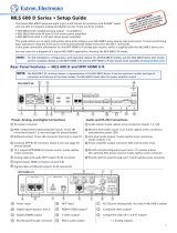
2. Assemble the supplied M4x50 Screw, Nut, and Washer as
the Figure 4.
3. Use the supplied template to mark the location where the
round hole is to be cut. Confirm the space behind the dash
or panel is deep enough to accommodate the MLS-310
(at least 4.3 inch (110 mm) deep). There should be at least
1 inch (2.5 cm) between the MLS-310’s heatsink.
4. Cut out the round hole (one large hole and four small
mounting holes) and inset the MLS-310 from the front
side.
5. Referring to Figure 5, pass through the four M4x50 Screws
(with Nut and Washer) into the mounting holes on the panel
from the back side and turn the M4x50 Screws five times.
6. Turn the four Nuts to adjust the tension so that the MLS-
310 is tight against the mounting surface.
7. Route and secure the connection cable from the MLS-310
to the Marine VHF. Connect the WHITE wire of the con-
nection cable to the marine VHF’s positive (+) external
speaker output and the shield of the connection cable to
the negative (–) external speaker connection.
8. Connect the RED wire of the connection cable from the
MLS-310 to a Positive (+) 12VDC positive source (ca-
pable of supplying 1.5A of current) and the BLACK wire
of the connection cable to Negative (–) 12VDC source.
OPERATION
1. Before connecting the MLS-310 to the radio, turn on the
radio and set the AF VOL level to minimum.
2. Turn the radio off then connect the MLS-310 to the radio.
3. Rotate the MLS-310 volume knob to “12 o’clock” posi-
tion.
4. Turn the radio on and adjust the VOL knob on the radio to
a comfortable listing level
5. After adjusting the volume on the radio, you may adjust
the MLS-310 volume or turn off the speaker using the
volume knob.
REPLACEMENT PARTS
Mounting Bracket (Black): RA0636400
Mounting Bracket (White): RA0636500
Mounting bracket Knobs (Black): RA045910A
Mounting bracket Knobs (White): RA043770A
Volume knob (Black): RA0652800
Volume knob (White): RA0635600
Mounting bracket mounting hardware: U9900147
Figure 3
Figure 5
Figure 4
Wall thickness + 1 inch
Washer Nut
M4x50 Screw
SPECIFICATIONS
Supply Voltage: 13.8 VDC ±15 %
Current Drain: 1.5 A @13.8 VDC,
VOL Knob MAX,
Audio Input Level: 700mVrms
Audio Input Level: 700mVrms (Nominal)
1Vrms (Maximum)
Input Impedance: 1.8 kΩ (Approx.)
Speaker Impedance:8 Ω
Audio Output: 8 W @13.8 VDC, 10% THD
Audio Input Level: 700mVrms
Maximum Audio Output: 10 W @13.8 VDC,
Audio Input Level: 700mVrms
Operating Temperature: –4 °F to +140 °F
(–20 °C to +60 °C)
Connection Cable Length: 6.5 feet (2 m)