Page is loading ...


lifebreath.com 1
Pre-Installation Notes
Note
•
Due to ongoing research and product development, specifications, ratings, and dimensions are
subject to change without notice. Refer to www.lifebreath.com for the latest product
information.
Attention
•
Do not apply electrical power to the unit until after the completion of the installation (including
installation of low voltage control wiring).
• Ensure the installation and wiring is in accordance with all local electrical codes.
• Plug the unit into a standard designated (120 VAC) electrical outlet with ground.
• The use of an extension cord with this unit is not recommended. If the installation requires
further wiring, have a licensed electrician make all the electrical connections. The
recommended circuit is a separate 15 A/120 V circuit.
Caution
•
Before installation, careful consideration must be given to how this system will operate if
connected to any other piece of mechanical equipment, i.e. a forced air furnace or air handler,
operating at a higher static. After installation, the compatibility of the two pieces of equipment
must be confirmed, by measuring the airflows of the ERV, by using the balancing procedure
found in this manual. Never install a ventilator in a situation where its normal operation, lack of
operation or partial failure may result in the back drafting or improper functioning of vented
combustion equipment
• Unit must be installed level to ensure proper condensate drainage. Due to the broad range of
installation and operational conditions, consider the possibility of condensation forming on
either the unit or connecting ducting. Objects below the installation may be exposed to
condensate.
• Do not install control wiring alongside electrical wire.
Warning
•
Disconnect the power from the unit before cleaning or servicing.
• To prevent electrical shock, it is extremely important to confirm the polarity of the power line
that is switched by the safety (disconnect) switch. The hot line (black) is the proper line for
switching. Use either a voltmeter or test lamp to confirm the absence of a voltage between the
disconnect switch and ground (on the cabinet) while the door is open. This procedure must be
followed, as dwellings are occasionally wired improperly. Always ensure the proper grounding
of the unit.
• Improper installation, adjustment, alteration, service or maintenance can cause property
damage, personal injury or loss of life. Installation and service must be performed by a
qualified installer or service agency.

lifebreath.com 2
Table of Contents
1 Location Notes ................................................................................................................................................................ 3
2 Ducting the System ......................................................................................................................................................... 4
3 Dimensional Drawings .................................................................................................................................................... 5
3 Dimensional Drawings .................................................................................................................................................... 6
4 The Integrated HVAC System .......................................................................................................................................... 7
5 The Integrated HVAC System .......................................................................................................................................... 8
6 Stale Air Return and Fresh Air Supply System ................................................................................................................ 9
7 Weatherhoods and Grilles ............................................................................................................................................ 10
8 Electrical Connections ................................................................................................................................................... 11
9 Functions and Controls ................................................................................................................................................. 12
10 Main Wall Control ..................................................................................................................................................... 13
11 Main Wall Controls ................................................................................................................................................... 14
12 Main Wall Control ..................................................................................................................................................... 15
13 Main Wall Control ..................................................................................................................................................... 16
14 Main Wall Control ..................................................................................................................................................... 17
15 Timers and Repeaters ............................................................................................................................................... 18
16 Timers and Repeaters ............................................................................................................................................... 19
17 Timers and Repeaters ............................................................................................................................................... 20
18 Timers and Repeaters ............................................................................................................................................... 21
19 Aircom Relays & Interlocking to a furnace/air handler ............................................................................................ 22
20 Fan Defrost ................................................................................................................................................................ 23
21 Balancing the Airflows .............................................................................................................................................. 24
22 Balancing the Airflows .............................................................................................................................................. 25
23 Service and Maintenance .......................................................................................................................................... 26
24 Service and Maintenance .......................................................................................................................................... 27
25 Reverse Installation of the ERV ................................................................................................................................. 28
26 Troubleshooting ........................................................................................................................................................ 29
27 Troubleshooting ........................................................................................................................................................ 30
28 Wiring Diagrams (330ERV) ........................................................................................................................................ 31
29 Wiring Diagrams (530ERV) ........................................................................................................................................ 32
30 Wiring Diagrams (730ERV and 1230ERV) .................................................................................................................. 33
31 Warranty ................................................................................................................................................................... 34

lifebreath.com 3
1 LOCATION NOTES
The unit must be in a heated space where the surrounding air temperature does not fall below 60°F
(16°C). The unit must be mounted level (horizontal) to obtain proper drainage of water from the heat
exchange element and drip pans. The warranty will be void if these conditions are not met. Typically,
the unit is positioned close to an outside wall or the roof to simplify the connections and keep the
length of insulated ducting required for the fresh air intake to a minimum.
A minimum clearance of 30 inches (76 cm) in front of the unit is recommended to service the heat
exchanger cores and the filters. The unit may be mounted on an equipment platform providing the
drain hoses are clear and there is enough space to open the doors for servicing.
Saddle Installation
(1) Threaded rod (not supplied)
(2) Vibration isolators (not supplied)
Hang unit with suspended rods and “U”
channel members.
Curb Mounted Installation
(1) Curb—Wood or Metal (not supplied)
(2) Vibration isolators (not supplied)
Mount unit on wooden or metal curb assembly.
May be anchored to floor.

lifebreath.com 4
2 DUCTING THE SYSTEM
A properly designed ducting system will allow the ERV to operate at its maximum efficiency. (Air flow
will be restricted by undersized ducting, use of too many elbows, tees, bends, etc.). Always try to
keep duct runs as short and straight as possible.
All joints must be airtight, sealed and impervious to moisture. See Dimensional Drawings for each
unit for exact duct sizes and location.
To minimize pressure drop and noise, galvanized metal ducts, properly sized, are recommended.
Keep ducting as short as possible and use a minimum of elbows and tees.
Connecting sections and shorter runs may be flexible ducting one size larger than the metal
equivalent. Use flexible duct connectors at the ERV to avoid noise transmission.
All duct joints must be secured with screws, rivets or duct sealant and sealed with aluminum duct
tape to prevent leakage.
Attention
• Flexible duct connectors should be installed between the HRV and the galvanized ductwork.
• Use fully insulated ducting with an integral vapour barrier on all runs that pass through unheated areas to
avoid condensation problems and energy losses from the air streams. Consult local codes.

lifebreath.com 5
3 DIMENSIONAL DRAWINGS
330ERV Dimensions:
530ERV Dimensions:

lifebreath.com 6
3 DIMENSIONAL DRAWINGS
730ERV Dimensions:
1230ERV Dimensions:

lifebreath.com 7
4 THE INTEGRATED HVAC SYSTEM
The ERV has become an integral component of the HVAC system. Figure A shows an ERV unit providing
fresh air directly to the return air plenum of a rooftop heat/cool unit.
In the balanced airflow system, the ERV exhaust removes stale room air (eg. from lunch room, storage or
copy area) and returns to the space an equal amount of fresh outdoor air, making the use of an
economizer obsolete in conjunction with an ERV.
Note
•
At no time should the air handler T.E.S.P. on the return duct exceed that of the ERV.
Caution
•
When interlocking a rooftop unit with an ERV take care to ensure the fans of both units
operate in the correct rotation.
Figure A
Note: Example configuration only.

lifebreath.com 8
5 THE INTEGRATED HVAC SYSTEM
Many buildings have ceiling return air plenum as in Figure B. Fresh air from the ERV can be introduced
directly into the ceiling space, but this should occur near the air handler’s intake.
By operating the ERV on a 24 hour / 7 day battery backed timer, the unit can be set to operate only when
occupancy or indoor conditions require the air exchange.
In installations where it is satisfactory to provide general exhaust from the space, the air to be exhausted
may be taken directly from the return air plenum to the ERV as it is drawn back to the air handler. Fresh
air supplied by the ERV is then introduced directly into the return air plenum but at a location closer to the
air handler. The air handler would have a constant running blower to effectively distribute the fresh air and
remove the stale air. Balancing dampers would be located in both the ERV supply and exhaust ducts
between the return air plenum and the ERV.
Figure B
Note: Example configuration only.

lifebreath.com 9
6 STALE AIR RETURN AND FRESH AIR SUPPLY SYSTEM
Stale Air Return System
Many commercial activities produce air contaminants in the form of dusts, fumes,
mists, vapors and gases. Contaminants should be controlled at the source, so they
are not dispersed through the building or allowed to increase to toxic
concentration levels. The ventilator allows for economical operation of the HVAC
system while effectively removing contaminants from the space. In designing the
exhaust portion of the system, the exhaust grilles are situated to remove the
contaminants while not allowing them to enter the breathing zone of the
occupants.
The stale air return system is used to draw air from the points in the building where the worst air quality problems occur.
Balancing dampers and/or adjustable grilles are recommended on all return air lines which are used during installation to
help balance the “draw” from different areas of the building.
For contaminants lighter than air, grilles should be located high on the wall. If contaminants are heavier than air, a lower
placement of the grilles will be required. Information on a contaminants specific gravity and toxicity should be available
from chemical data sheets.
Alternately, the stale air may be drawn directly from the return air duct. When this system is used, the air handler’s
blower must constantly operate. The exhaust take-off connection must be at least 3 ft (1 m) from a directly connected
ERV supply duct if both are connected to the same duct run. Note and compensate for the static pressure of the air
handlers return system if the static pressure of the return in the air handler exceeds 0.1 to 0.15 in. w.g.
A damper located just prior to the ERV is required to balance the stale air exhausted with the fresh air supply entering the
building.
Return air suction points should be located on the opposite side of the room from the fresh air inlet.
The inlets may be in the ceiling or high on the walls and fitted with inlet grilles.
Fresh Air Supply System
The fresh air supply ductwork from the ERV may be directly connected to the
return air duct of the forced air system. Check the air flow balance of the ERV
with the air handler blower both “ON” and “OFF” to determine that it does not
imbalance the ERV more than 10%. Also, it is advisable to include a short length
of flex duct or other non-metallic connector in this hard ducted line in order to
keep the ERV acoustically isolated and separately grounded (electrically) from
the air handler. This will avoid a possible shock hazard to service people if a
short to ground develops in one of the devices.
When installing an ERV, the designer and installer should be aware of local codes that may require smoke detectors
and/or firestats in the HVAC or ERV ductwork. Because an ERV is designed to bring fresh air into the building, structures
may require supply voltage interrupt when smoke or flame sensors are triggered, or when a central fire alarm system is
activated.
It may be necessary to install a separate fresh air supply ductwork system if the heating is other than forced air.
Supply air grilles may be ceiling or high wall mounted. Avoid locating incoming fresh air grilles that could cause a direct
draft on the occupants as the incoming air may be below room temperature. A reheat duct heater can be installed to
improve occupant comfort.

lifebreath.com 10
7 WEATHERHOODS AND GRILLES
Outside Weatherhoods:
• The weatherhoods must have built-in “bird” screen with 1/4 in (6.35 mm) minimum mesh to prevent
birds and rodents from entering the ductwork.
Recommended:
o no less than 10 ft. (3 m) apart from each other
o at least 18 in (46 cm) above snow line or ground level
o away from sources of contaminants, such as automobile exhaust fumes, gas meters, garbage cans,
containers, etc.
o not exposed to prevailing winds
o The outside perimeter of the weatherhood must be caulked to prevent leakage into the building.
o The design and size of the weatherhoods or louvers chosen by the installer must allow for adequate
free area. Water and debris penetration of the system is minimized when the airflow does not
exceed 1000 FPM (5.08 m/s) free area velocity.
Ducting from the Weatherhoods:
• Galvanized sheet metal ducting with sufficient cross section with an integral single piece vapor barrier
should be used to connect the ERV to the weatherhoods.
• A minimum R value of insulation should be equal to 4 (RSI 0.75)
• A good bead of high quality caulking (preferably acoustical sealant) and taping with a high quality
aluminum foil tape is recommended to seal the duct to both the ERV and the weatherhood.
Techgrilles:
• The use of balancing dampers or adjustable grilles as supply air diffusers and air exhaust covers are
recommended. TECHGRILLES™ are round, efficient, sound absorbing devices available in 4”, 5”, 6” and
8” (100, 125, 150, and 200 mm) models.
Part# 99-EAG4 4” diameter Techgrille
Part# 99-EAG5 5” diameter Techgrille
Part# 99-EAG6 6” diameter Techgrille
Part# 99-EAG8 8” diameter Techgrille
Attention
•
All ducting must meet UL Class 1 requirements
• Design and install the fresh air intake in an area where the hoods will gather the freshest air.
• Do not use smaller mesh as it will be very susceptible to plugging up. Gravity dampers at the vents
must not be used as they will restrict air flow and often “seize up”.

lifebreath.com 11
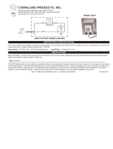
8 ELECTRICAL CONNECTIONS
It is recommended that a licensed electrician make all electrical connections. It is very important that
the unit be properly grounded. The circuit must be sized to handle the Full Load Amperage (FLA)
indicated on the name tag for the circuit.
.
Maximum AMP Rating
HIGH
MED.
LOW
1230ERV
9.4
6.0
4.5
730ERV
4.5
3.2
2.4
530ERV
3.2
-
2.4
330ERV
2.0
1.4
1.0
Warning
•
Verify the polarity of the power coming into the unit with a test lamp or multimeter. Connect the
multimeter or test lamp probe to the wire being tested and the other probe to ground. The black
line should be “live”. If the white line is “live” the polarity is reversed and must be corrected. If
both lines are live, the voltage is not 120VAC. The black open line from the unit should be
connected to the live line and the white open line should be connected to the neutral line. Some
unit have a safety disconnect rocker switch located just outside of the electrical control box area.
The switch disconnects the live line. Verify that it is working properly with a multimeter or test
lamp. Always ensure the ERV is properly grounded before and after testing.
Caution
• The ERV is designed to operate with ducting. When first starting the ERV, measure the amp draw to
each motor at each speed to ensure it is operating at or below the max rating.

lifebreath.com 12
9 FUNCTIONS AND CONTROLS
Basic Functions
Speed control is obtained by powering 24V to one of the designated speed taps. Select appropriate operational
speed by installing the jumper wire between one of the designated speed taps on the Thermostat terminals on
the micro process board. A jumper wire is factory installed in the low speed position.
Micro Processor Board
Optional Ventilation Control (99-BC02, 99-
BC03, or 99-BC04)
See Page 16 for installation on circuit board.
Optional 3 Speed Control (99-500)
See Page 17 for installation on circuit board.
Optional Wireless Timer (99-DET02)
See Page 19 for installation.
Optional Wireless Repeater (99-RX02)
See Page 20 for installation.
Optional 20/40/60 Minute Timer (99-DET01)
See Page 21 for installation on circuit board.
Speed
Jumper Wire Placement
High
R
W
Medium
R
Y
Low (factor setting)
R
G
Note
•
It is recommended to use the optional speed control Part # 99-500 in order to obtain 3 speed fan
control.

lifebreath.com 13
10 MAIN WALL CONTROL
Ventilation Wall Control (99-BC02)
Operating Instructions:
(1) ON/OFF Button
(2) Dehumididstat Button
(3) Fan Button
(4) Fan Speed Indicator
(5) Humidity Setting
(6) ON/OFF light
Turning on the Control:
Press the ON/OFF Button . The ON/OFF light will illuminate.
Setting the Ventilation Speed:
Press the Fan Button to select LOW or HIGH fan speed. The
corresponding indicator light will illuminate. If both LO and HI
indicator lights are off, the fan is OFF, but will turn ON if required
by the Dehumidistat or remote timer (if installed).
Humidity Control:
Your unit will reduce indoor humidity when outdoor humidity
levels are lower than indoor humidity levels. This feature is only effective when the outdoor temperature is
below 59°F (15°C).
Setting the Dehumidistat:
Press the Dehumidistat button until the dehumidistat indicator light is at the desired humidity setting.
After a few seconds the dehumidistat indicator light will either flash or be on continuously. A flashing light
indicates the humidity level is higher than the humidity setting and the unit is operating on high speed
ventilation. A continuous light indicates the humidity level is lower than the humidity setting. The
Dehumidistat will override the current speed setting to HIGH speed. The Dehumidistat function can be
turned off by pressing the button until the dehumidistat indicator light turns off.
Attention
•
Only one main control can be installed on your system.
• Recirculation is not available on all models.
• Timers will not function when mode of operation is set to “OFF”, unless specifically installed
for the function. (See Installation Guide for other options.)

lifebreath.com 14
11 MAIN WALL CONTROLS
Ventilation Wall Control (99-BC03)
Operating Instructions:
(1) ON/OFF Button
(2) Dehumididstat Button
(3) Mode Button
(4) Recirculation Mode Indicator
(5) 20/40 Mode Indicator
(6) Humidity Setting
(7) LOW Fan Speed Indicator
Turning on the Control:
Press the ON/OFF Button . The LOW fan speed indicator will
illuminate, and fan will turn to LOW speed.
Humidity Control:
Your unit will reduce indoor humidity when outdoor humidity levels
are lower than indoor humidity levels. This feature is only effective
when the outdoor temperature is below 59°F (15°C).
Setting the Dehumidistat:
Press the Dehumidistat Button until the dehumidistat light is at the desired setting. After a few seconds
the dehumidistat light will either flash or be on continuously. A flashing light indicates the humidity level is
higher than the set point and that the unit is operating on HIGH speed ventilation. A continuous light
indicates the humidity level is lower than the set point. The Dehumidistat will override the current speed
setting to HIGH speed. The Dehumidistat function can be turned off by pressing the Dehumidistat Button
until the dehumidistat light turns off.
Setting the 20/40 Mode:
Press the Mode Button until the 20/40 mode indicator light is illuminated. The 20/40 mode is a
repeating cycle. The fan will run at LOW speed for 20 minutes, then turn OFF for 40 minutes. Some units
are equipped to recirculate the air in your home during the 40-minute cycle with no ventilation. The control
will automatically detect this feature and recirculate the air during the 40-minute cycle at LOW fan speed.
Recirculation Mode:
Some units are equipped to recirculate the air in your home without ventilating. Press the Mode Button
until the recirculation mode indicator light illuminates. Recirculation is in LOW speed.
Attention
• Only one main control can be installed on your system.
• Recirculation is not available on all models.
• Timers will not function when mode of operation is set to “OFF”, unless specifically installed for the
function. (See Installation Guide for other options.)

lifebreath.com 15
12 MAIN WALL CONTROL
Ventilation Wall Control (99-BC04)
Operating Instructions:
(1) ON/OFF Button
(2) 20/40 Button
(3) Fan Button
(4) Fan Speed Indicator
(5) 20/40 Mode Indicator
(6) ON/OFF Indicator
Turning on the Control:
Press the ON/OFF Button . The ON/OFF indicator light will
illuminate.
Setting the Ventilation Speed:
Press the Fan button to select LOW or HIGH fan speed. The
corresponding indicator light will illuminate. If both LO and HI
indicator lights are off, the fan is OFF, but will turn ON if
required by a remote timer (if installed).
Setting the 20/40 Mode:
After a fan speed has been selected, press the 20/40 button. The 20/40 mode indicator light will illuminate.
The 20/40 mode is a repeating cycle. The fan will run at LOW or HIGH speed for 20 minutes, then turn
OFF for 40 minutes. Some units are equipped to recirculate the air in your home during the 40-minute
cycle with no ventilation. The control will automatically detect this feature and recirculate the air during the
40-minute cycle at the selected fan speed.
Attention
•
Only one main control can be installed on your system.
• Recirculation is not available on all models.
• Timers will not function when mode of operation is set to “OFF”, unless specifically
installed for the function. (See Installation Guide for other options.)

lifebreath.com 16
13 MAIN WALL CONTROL
The 99-BC02, 99-BC03, 99-BC04 ventilation controls may either be installed onto a flush mounted electrical switch box or
surface mounted onto a wall. Only one main control should be installed into a ventilation system.
Installation:
1. Carefully separate the face plate
and the back plate by firmly
pulling it apart. Keep the
top/bottom vent openings clear
(figure A).
2. Position the back plate in the
desired location on the wall and
mark the wall for the desired
screw holes (figure B).
3. For mounting the main control
without a Decora plate, break off
the top and bottom tabs than
position the back plate in the
desired location on the wall and
mark the wall for the desired
screw holes (figure C)
4. Remove the back plate from the
wall and mark the hole for the
wires centered between the two
screw holes (figure B or C).
5. Drill two 1/8 in. holes for the
screws and wall anchors and drill
one 1 in. x 0.75 in. hole for the
wires.
6. Pull the 3 wire 20 gauge (min.),
100 ft length (max.), through the
opening in the wall.
7. Connect the wires to the R, G, and
Y terminals on the back plate
(figure B or C).
8. Using the two supplied screws and
anchors, install the back plate on
the wall.
9. Attach the face plate to the back plate (figure A).
10. Connect the 3 wire 20 gauge (min.), 100 ft length (max.), to the RED, GRN, and YEL terminal on the Digital Controls
terminal strip on the Aircom circuit board (figure D).
Attention
• Use care when separating or attaching the face plate to avoid damaging the contact pins.

lifebreath.com 17
14 MAIN WALL CONTROL
3-Speed Control (99-500) Operation:
(1) High Speed Fan
(2) Medium Speed Fan
(3) Low Speed Fan
Press the applicable Fan Speed button to set the fan speed. Press the
applicable OFF button in order to turn the Fan Speed control off.
3-Speed Control (99-500) Installation:
Connect the wires to the R, W, Y, and G terminals on the Aircom circuit board as shown.
Attention
•
Use 4 wire; 20-gauge wire (minimum)
• When used in conjunction with the 99-BC04, the BC04 control must be ON for the 99-500 control
to operate. The 99-BC04 will override the 99-500 control when the control is set to HIGH speed

lifebreath.com 18
15 TIMERS AND REPEATERS
20/40/60 Minute Wireless Timer (99-DET02) Operation:
(1) Select Button
(2) 20/40/60 minute status lights
(3) Red LED battery indicator
Press the Select Button on the timer to initiate high speed ventilation for
20, 40, or 60 minutes. The 20/40/60 minute status lights indicate high
speed operation. To cancel the high speed fan operation, press the
Select Button until the 20/40/60 minute status lights are no longer
illuminated.
When the battery in the timer needs to be replaced, the red LED Battery
Indicator will illuminate.
When paired to the digital wall control, the wireless timer may be moved
to a remote location in the home such as a bathroom. Wireless timers
have an estimated range of 40 ft with no obstructions
Replacing the Timer Battery (99-DET02):
(4) Battery
(5) Face plate
(6) Back plate
a) Remove the face plate by
separating it from the back plate.
On the back of the face plate the
battery will be exposed.
b) Replace the battery and re-attach
the face plate to the back plate.
Attention
•
Be careful not to damage the tabs on the back plate when re-attaching the face plate.

lifebreath.com 19
16 TIMERS AND REPEATERS
Wireless 20/40/60 Minute Timer (99-DET02)
The timers may be installed onto a flush mounted electrical switch box or it may be surfaced mounted onto a wall.
Pairing:
1. Remove the battery from the back of the timer,
if installed.
2. Press the ON/OFF Button on the main control
to turn it on.
3. BC02, BC03, or BC04: Press the left and right
buttons ( and or ) simultaneously on
the main control. The bottom row LEDs will
begin flashing. This indicates the main control is
now in pairing mode.
4. Keep the timer within 16 in. of the main control
when pairing.
5. Install the battery into the remote timer. The
four lights will immediately flash five times. The
red battery light will remain on for 12 seconds,
then the 40 minute status light will flash. The
20, 40, and 60 minute status lights will flash for
up to 30 seconds and then stop.
6. Press the Power Button on the main control
to exit pairing mode.
7. Press the Select Button on the timer to test that
pairing was successful (figure A).
• If the ERV initiates HIGH fan speed
ventilation, pairing was successful.
• If the ERV does not initiate HIGH fan speed
ventilation, pairing was not successful. Un-
pair the timer and return to step 1 of the pairing procedure and restart the pairing process.
8. Pair additional timers as necessary by repeating steps 1 through 8.
Un-pairing:
1. Remove the battery from the back of the timer.
2. Press and hold the Select Button on the front of the timer (figure A).
3. While holding the Select Button, reinstall the battery in the timer. Continue holding the Select Button until the 20, 40,
and 60 minute status light begins flashing (this can take up to 30 seconds). The timer will now be unpaired with the
main control (figure A).
Installation:
1. Separate the face plate from the back plate by firmly pulling apart (figure B).
2. For mounting the main control without a Decora plate, break off top and bottom tabs (figure C).
3. Place the back plate of the main control in the desired location on the wall and pencil mark the top and bottom screw
holes. Drill two 1/8" holes (figure C or D).
4. Attach the back plate to the wall using the two supplied screws and anchors.
5. Attach the face plate to the back plate (figure B).
Attention
• The wireless timers and repeaters must be paired to the main control of the ERV. This process is called
“Pairing”. Multiple timers and repeaters can be paired to the digital wall control.
Figure A
/