Page is loading ...

1
Assembly Instructions
Land Pride
© Copyright 2002 Printed 3/13/02 340-300M
A separate Parts Manual for replacement parts can be
purchased from your dealer or downloaded from our
website at www.landpride.com. Have model and serial
numbers handy when placing an order.
Manual Part Numbers:
•340-036M OPERATOR’S MANUAL BH1560/75
•340-036P PARTS MANUAL BH1560/75
General Information
These instructions apply to the Mounting Kit:
340-151A FRAME MOUNT & STAB KIT KUB BX
BH1560/75
On page 12 is a detailed listing of parts included in this kit.
Use this list as a checklist to inventory parts received.
Assembly Instructions
The following Assembly will be more easily performed if
the rear tires are removed and the rear of the tractor is
safely supported.
1. Refer to Figure 1. Remove the three bolts (A) and
lockwashers. These will be used to mount the
brackets in the next step. Remove the three bolts and
lockwashers (B). Discard bolts and keep the
lockwashers.
When you see this symbol, the subsequent
instructions and warnings are serious - follow
without exception. Your life and the lives of others
depend on it!
!
Before You Start
These assembly instructions contain only information on
assembling the BH1560 & BH1575 mounting kit to the BX
Series Kubota Tractor. A detailed Operator’s Manual was
supplied with the main unit when it was purchased. For
more specific information on safety concerns refer to the
Operator’s Manual. Also included in the Operator’s
Manualisimportant informationon operation,adjustment,
troubleshooting,andmaintenanceforthisBackhoe(some
of these sections do not apply to all options).
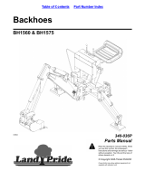
Figure 1
BH1560 & BH1575
Kubota BX1800 - BX2200
Mounting Kit
A
A
B
B
B

2
BH1560 & BH1575 Mounting Kit 340-300M
3/13/02
Land Pride
Assembly Instructions
2. Refer to Figure 2. Assemble Left Hand and Right
Brackets as shown. Install bolts and lockwashers that
were removed in Step 1 in locations labeled "B".
Install supplied bolts and the lockwashers that were
kept from Step 1 in locations labeled "A".
3. Mount rear tires on tractor and place tractor back on
ground.
Mounting Bracket
Figure 2
BB
B
A
A

3
3/13/02
BH1560 & BH1575 Mounting Kit 340-300M
Land Pride
Assembly Instructions
4. Refer to Figure 3. Remove the lower hitch brackets
that are currently mounted to the backhoe. Assemble
the brackets supplied in the mounting kit as shown.
Mounting hardware is supplied with kit or hardware
that was removed from brackets may be used.
Figure 3
Lower Brackets


6
BH1560 & BH1575 Mounting Kit 340-300M
3/13/02
Land Pride
Assembly Instructions
7. Assemble PTO Drive adapter to PTO pump as shown
in Figure 6.
Figure 6
PTO Drive Adapter
PTO Pump
8. Assemble the Suction Pump Adapter and Pressure
Pump Adapter to the Pump as shown in Figure 7.
Figure 7
PTO Pump
Suction Pump Adapter
Pressure Pump Adapter


8
BH1560 & BH1575 Mounting Kit 340-300M
3/13/02
Land Pride
Assembly Instructions
Suction Hose
Return (Pressure) Hose
Inlet Hose
Elbow
Hose Clamp
10. Assemble Suction Hose (Large Hose) end without
fitting to Hydraulic Reservoir with Hose Clamp.
Assemble the end with fitting to the Pump Suction
Adapter.
11. Assemble Elbow Adapter to Hydraulic Reservoir
making sure that elbow is pointing up.
12. Disconnect hose from inlet side of valve and connect
to Elbow on Hydraulic Reservoir.
13. Disconnect Return Hose (Pressure) and connect to
Pressure Adapter on Pump.
Pump
Suction Filter
Oil Reservoir
(Backhoe or
Tractor
Sump)
Inlet Valve of
Backhoe Valve
Return Hose
From Backhoe
Valve
Press.
Tank
Figure 9
Figure 10

9
3/13/02
BH1560 & BH1575 Mounting Kit 340-300M
Land Pride
Assembly Instructions
14. Assemble torque bar to Pump with 3/8" bolts and
locknuts as shown.
15. Back tractor up to backhoe just close enough to
assemble the Pump to tractor’s PTO drive shaft. Do
notbackcompletelyup tobackhoe.Leavesome room
for PTO pump and assembly. The Pump should be
assembled so that the Torque Bar is pointing up.
16. Set lower 3-point arms 9" from ground to center of
swivel ball, then back the tractor until lower 3-point
align with lower mounting brackets on the backhoe
then attach accordingly.
Figure 11
Torque Bar
3/8" Bolts & Locknuts
PTO Pump

10
BH1560 & BH1575 Mounting Kit 340-300M
3/13/02
Land Pride
Assembly Instructions
17. Align tractor’s lower 3-point arms and locking bar with
the bottom holes of backhoe’s lower 3-point brackets.
The locking bar will be beneath the lower 3-point
arms.Install pinsandsecurewithlynchpins.Alignthe
locking bar’s eyebolts with the top holes of the
Backhoes 3-point brackets. Install pins and secure
with lock pins. There may be some adjustment of the
eyebolts to align with the top holes.
Figure 12
Locking Bar
Pins
Lock Pins
Eyebolt
Adjustment Nuts
3-Point Arms Above Locking Bar

11
3/13/02
BH1560 & BH1575 Mounting Kit 340-300M
Land Pride
Assembly Instructions
Frame Stabilizer Bar Assembly
1. Place the Stabilizer Bar between the frame to make
sureitwill fit.TheStabilizerBarend platesmightneed
to be tweaked so that it fits between the frame as
shown.
2. Assemble the two hole plate to the threaded hole of
the Stabilizer Bar as shown capturing the frame
between the Bar and the two hole plate.
3. Place the flat washer on the bolt and insert it through
the top hole of two hole plate, through the hole in the
tractorframeandthroughthetopholeoftheStabilizer
Bar.
4. Assemble the one hole plate to the other end of the
StabilizerBar,capturingthetractorframebetweenthe
bar and the plate.
Disassembly
1. Lower bucket & stabilizers to the ground to get a
sturdy base before any pin or pump removal.
2. Disconnect the Pump from the tractor’s PTO shaft.
3. Disassemble the locking bar completely. Top link and/
or stabilizer need to be unpinned before removing
backhoe.
4. Drive away from Backhoe.
Figure 13
Stabilizer Bar
Bolt
Bolt, flat washer, lock
washer and nut
Two hole plate
One hole plate

Land Pride
Listing of Parts
BH1560 & BH1575 Mounting Kit 340-300M
3/13/02
12
340-151A FRAME MOUNT & STAB. KIT KUB BX BH1560/75
Your Kit Includes:
1 340-053K 3 PT STABILIZER KIT BH1575
Qty. Part No. Part Description
5 839-526C 1/4" LINCH PIN BH STABILIZE
2 839-528C ADJ.STABILIZER LINK CAT1 BH
5 839-529C PIN,3/4X4 1/2 W/LOOP BH
Qty. Part No. Part Description
1 340-293K FRME MNT KUB BX 1560
Qty. Part No. Part Description
1 340-022D WASHER W/1 HOLE 3/8X3SQ.
1 340-023D WASHER W/2 HOLE 3/8X2X3 3/4
1 340-303H FRAME MOUNT BRKT RH BX18/22
1 340-304H FRAME MOUNT BRKT LH BX18/22
1 340-305H CROSSTUBE WELDMT BX18/22
1 340-306H SPCL LWR LINK BRKT RH BX18/22
1 340-306H SPCL LWR LINK BRKT LH BX18/22
8 802-055C HHCS 5/8-11X2 GR5
2 802-184C HHCS 3/4-10X1 1/2 GR5
8 803-024C NUT LOCK 5/8-11 PLT
8 804-019C WASHER FLAT 5/8 USS PLT
2 804-023C WASHER LOCK SPRING 3/4 PLT
13 804-076C WASHER LOCK 9/16 PLT
3 839-526C 1/4" LINCH PIN BH STABILIZE
1 839-529C PIN,3/4X4 1/2 W/LOOP BH
2 839-659C PIN LOWER HITCH 7/8X3 1/
2 839-828C PIN HITCH 1X5 3/4 CAT II 25
6 839-943C CAPSCREW 14MMX1.5MMX50MM
3 839-944C CAPSCREW 9/16-12X1 3/4
2 839-945C PIN CLEVIS 3/4X3 1/2
2 839-946C FITTING ADAPTOR C5205X6X6
1 839-947C HOSE 3/8X1/2MALEX9/16JICFX7
1 839-948C HOSE 3/8X1/2MALEX9/16JICFX6
1 839-949C NUT HEX 9/16-12
Qty. Part No. Part Description
/