Page is loading ...

Please scan this QR code to have
access to our APPs and Products
information
APsystems QT2 3-Phase Microinverter
(For APAC)
APsystems Microinverter Installation Manual
©All Rights Reserved
ALTENERGY POWER SYSTEM Inc.
global.APsystems.com
APsystems Shanghai:
Rm.B305 No.188, Zhangyang Road, Pudong, Shanghai 200120,P.R.C
EMAIL: info.apac@APsystems.com

APsystems Microinverter QT2 Installation Manual
1
Table of Contents
1. Important Safety Instructions ......................................................................................................... 2
1.1 Safety Instructions.......................................................................................................................................... 2
1.2 Radio Interference Statement........................................................................................................................ 3
1.3 Symbols in lieu of words.................................................................................................................................4
2. APsystems Microinverter System Introduction .............................................................................. 4
3. APsystems Microinverter QT2 Introduction ................................................................................... 7
4. APsystems Microinverter System Installation ................................................................................ 8
4.1 Additional accessories supplied by APsystems ..............................................................................................8
4.2 Other required accessories not supplied by APsystems ............................................................................... 8
4.3 PV Rapid Shut Down Equipment.................................................................................................................... 9
4.4 Installation Procedures.................................................................................................................................10
4.4.1 Step 1 - Verify that grid voltage matches microinverter rating........................................................ 10
4.4.2 Step 2 – AC Bus Cable distribution....................................................................................................10
4.4.3 Step 3 - Attach the APsystems Microinverters to the Racking......................................................... 10
4.4.4 Step 4 - Ground the system...............................................................................................................11
4.4.5 Step 5 - Connect the APsystems microinverter to AC bus cable...................................................... 12
4.4.6 Step 6 - Install a Bus Cable End Cap at the end of AC bus cable...................................................... 13
4.4.7 Step 7 - Connect APsystems Microinverters to the PV Modules......................................................13
4.4.8 Step 8 - Connect APsystems Microinverters to Grid.........................................................................14
4.4.9 Step 9 - AC Extension Cable.............................................................................................................. 15
4.4.10 Step 10 - Complete the APsystems installation map...................................................................... 15
5. APsystems microinverter system operating instructions .............................................................16
6. Troubleshooting .............................................................................................................................17
6.1 Status Indications and Error Reporting ........................................................................................................ 17
6.1.1 Start up LED ....................................................................................................................................... 17
6.1.2 Operation LED................................................................................................................................... 17
6.1.3 GFDI Error.......................................................................................................................................... 17
6.2 ECU_APP....................................................................................................................................................... 17
6.3 Installer EMA (web portal or EMA Manager APP)....................................................................................... 17
6.4 Trouble Shooting Guide................................................................................................................................17
6.5 APsystems Technical Support....................................................................................................................... 18
6.6 Maintenance .................................................................................................................................................18
7. Replace a microinverter ................................................................................................................ 19
8. Technical Data ................................................................................................................................20
8.1 QT2 3-Phase Microinverter Datasheet.........................................................................................................21
9. QT2 - Wiring Diagram .................................................................................................................... 22
9.1 QT2 Connected To Detla Type 3-Phase Grid................................................................................................ 22
9.2 QT2 Connected To Wye 3-Phase Grid.......................................................................................................... 23
10.QT2 Accessory ...............................................................................................................................24
10.1 Dimensions ................................................................................................................................................. 24
10.2 Wiring Diagram...........................................................................................................................................25
11.APsystems Microinverter Installation Map ................................................................................. 26

APsystems Microinverter QT2 Installation Manual
2
1. Important Safety Instructions
This manual contains important instructions to follow during installation and maintenance of the APsystems
Photovoltaic Grid-connected Microinverter. To reduce the risk of electrical shock and ensure a safe installation
and operation of the APsystems Microinverter, the following symbols appear throughout this document to
indicate dangerous conditions and important safety instructions.
Specifications are subject to change without notice. Please ensure you are using the most recent update found at
https://global.apsystems.com/resources/library/
This indicates a situation where failure to follow instructions may cause a serious hardware failure or
personnel danger if not applied appropriately. Use extreme caution when performing this task.
This indicates information that is important for optimized microinverter operation. Follow these
instructions closely.
1.1 Safety Instructions
Do NOT disconnect the PV module from the APsystems Microinverter without first disconnecting the AC
power.
Only qualified professionals should install and/or replace APsystems Microinverters.
Perform all electrical installations in accordance with local electrical codes.
Before installing or using the APsystems Microinverter, please read all instructions and cautionary markings
in the technical documents and on the APsystems Microinverter system and the solar-array.
Be aware that the body of the APsystems Microinverter is the heat sink and can reach a temperature of 80°C.
To reduce risk of burns, do not touch the body of the Microinverter.
Do NOT attempt to repair the APsystems Microinverter. If it fails, contact APsystems Customer Support to
obtain an RMA number and start the replacement process. Damaging or opening the APsystems
Microinverter will void the warranty.
Caution!
The external protective earthing conductor is connected to the inverter protective earthing terminal
through AC connector. When connecting, connect the AC connector first to ensure the inverter earthing
then do the DC connections. When disconnecting, disconnect the AC by opening the branch circuit breaker
first but maintain the protective earthing conductor in the branch circuit breaker connect to the
inverter ,then disconnect the DC inputs.
Please install AC breakers on the AC side of the inverter.
CAUTION – Hot surfaces - To reduce the risk of burns - Do not touch. Risk of electric shock-(a) both ac and
dc voltage source are terminated inside this equipment. Each circuit must be individually disconnected
before servicing, and (b) When the photovoltaic array is exposed to light, it supplies a dc voltage to this
equipment. Warranty void if cover removed. No user serviceable parts inside.Refer servicing to qualified
service personnel. This inverter has an integral ground-fault detector / interrupter (GFDI).This
Utility-InteractiveInverter contains active anti-islanding protection(IEEE1547) and is tested per FCC/IC.

APsystems Microinverter QT2 Installation Manual
3
1. Important Safety Instructions
1.2 Radio Interference Statement
This equipment has been tested and found to comply with the limits for a Class B digital device, pursuant to
part 15 of the FCC Rules. These limits are designed to provide reasonable protection against harmful
interference in a residential installation. This equipment generates, uses and can radiate radio frequency
energy and, if not installed and used in accordance with the instructions, may cause harmful interference to
radio communications. However, there is no guarantee that interference will not occur in a particular
installation. If this equipment does cause harmful interference to radio or television reception, which can be
determined by turning the equipment off and on, the user is encouraged to try to correct the interference by
one or more of the following measures:
Reorient or relocate the receiving antenna.
Increase the separation between the equipment and receiver.
Connect the equipment into an outlet on a circuit different from that to which the receiver is connected.
Consult the dealer or an experienced radio/TV technician for help.
RF exposure warning
This equipment must be installed and operated in accordance with provided instructions and the
antenna(s) used for this transmitter must be installed to provide a separation distance of at least 20 cm
from all persons and must not be co-located or operating in conjunction with any other antenna or
transmitter. End-users and installers must be provide with antenna installation instructions and transmitter
operating conditions for satisfying RF exposure compliance.

APsystems Microinverter QT2 Installation Manual
4
1. Important Safety Instructions
1.3 Symbols in lieu of words
Trademark.
Caution, risk of electric shock.
Caution, hot surface.
NOTICE, danger!This device directly connected with electricity generators and public grid.
Qualified personnel
Person adequately advised or supervised by an electrically skilled person to enable him or her to
perceive risks and to avoid hazards which electricity can create. For the purpose of the safety
information of this manual, a "qualified person" is someone who is familiar with requirements for
safety, electrical system and EMC and is authorized to energize, ground, and tag equipment,
systems, and circuits in accordance with established safety procedures. The inverter and
photovoltaic system may only be commissioned and operated by qualified personnel.
English Warning Statement:
This device complies with Industry Canada license-exempt RSS standard(s). Operation is subject to the
following two conditions: (1) this device may not cause interference, and (2) this device must accept any
interference, including interference that may cause undesired operation of the device.
French Warning Statement:
Le présent appareil est conforme aux CNR d'Industrie Canada applicables aux appareils radio exempts de
licence. L'exploitation est autorisée aux deux conditions suivantes : (1) l'appareil ne doit pas produire de
brouillage, et (2) l'utilisateur de l'appareil doit accepter tout brouillage radioélectrique subi, même si le
brouillage est susceptible d'en compromettre le fonctionnement.

APsystems Microinverter QT2 Installation Manual
5
2. APsystems Microinverter System Introduction
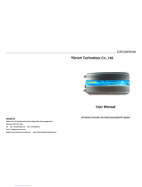
The APsystems Microinverter is used in utility-interactive grid-tied applications, comprised of three key elements:
APsystems Microinverter
APsystems Energy Communication Unit (ECU)
APsystems Energy Monitor and Analysis (EMA) web-based monitoring and analysis system
Figure 1
SOLAR
PANEL
ENERGY COMMUNICATION UNIT
ECU
EMAInternet

APsystems Microinverter QT2 Installation Manual
6
2. APsystems Microinverter System Introduction
This integrated system improves safety; maximizes solar energy harvest; increases system reliability, and
simplifies solar system design, installation, maintenance, and management.
Safety with APsystems Microinverters
In a typical string inverter installation, PV modules are connected in series. The voltage adds-up to reach high
voltage value (from 600Vdc up to 1000Vdc) at the end of the PV string. This extreme high DC voltage brings a risk
of electrical shocks or electrical arcs which could cause fire.
When using an APsystems microinverter, PV modules are connected in parallel. Voltage at the back of each PV
module never exceeds PV modules Voc, which is lower than 60Vdc for most of PV modules used with APsystems
microinverters. This low voltage is considered “safe to touch” by fire departments and negates the risk of
electrical shock, electrical arcs and fire hazards.
APsystems Microinverters maximize PV energy production
Each 2 input channels have individual Maximum Peak Power Tracking (MPPT) control, which ensures that the
maximum power is produced to the utility grid regardless of the performance of the PV modules of other
channels in the array. When PV modules in the array are affected by shade, dust, different orientation, or any
situation in which one channel underperforms compared with the other channels, the APsystems Microinverter
ensures top performance from the array by maximizing the performance of each channel individually within the
array.
More reliable than centralized or string inverters
The distributed APsystems Microinverter system ensures that no single point of system failure exists across the
PV system. APsystems Microinverters are designed to operate at full power at ambient outdoor temperatures of
up to 65 deg C (or 149 F). The inverter case is designed for outdoor installation and complies with the Type 6
environmental enclosure rating.
Simple to install
APsystems Microinvertes are compatible with most of 60 and 72 cell PV modules or 120 and 144 half-cut cells PV
modules. (In order to confirm compatibility of PV module with APsystems microinverter, feel free to check our
online “E-decider” module compatibility tool or contact your local APsystems Technical Support).
Installation requires a minimum number of accessories and microinverters offer a lot of versatility to the installer:
microinverters can indeed be installed on different roofs with different orientation or with modules having
different orientation.
In the same way, end-users can extend their system whenever they want with microinverters.
Smart system performance monitoring and analysis
The APsystems Energy Communication Unit (ECU) is installed by simply plugging it into any wall outlet and
providing an Ethernet or Wi-Fi connection to a broadband router or modem. After installing and setting the ECU
(see ECU Instruction Manual), the full network of APsystems Microinverters automatically reports to the
APsystems Energy Monitor and Analysis (EMA) web server.

APsystems Microinverter QT2 Installation Manual
7
3. APsystems Microinverter QT2 Introduction
APsystems introduces its 2nd generation of native 3-phase quad microinverters, reaching unprecedented power
outputs of 2000VA to harness the power of today’s high-output PV modules. The QT2 microinverter gives
commercial installers a powerful plug-and-play MLPE inverter that installs faster than competing solutions and is
inherently compliant to rapid shutdown requirements.
With balancing 3-phase output, 4 DC inputs and encrypted ZigBee wireless, installers and system owners alike
benefit from new QT2 architecture platform. The innovative design facilitates thermal dissipation while
maximizing power production. The components are encapsulated with silicone to reduce stress on the
electronics, dissipate heat, enhance waterproof properties, and ensure maximum reliability of the system. 24/7
access to performance data through apps or APsystems EMA web-based portal facilitate remote diagnosis and
troubleshooting.
The new QT2 is grid interactive through its Reactive Power Control (RPC) feature, designed to better manage
photovoltaic power spikes in the grid. At 96.5% peak efficiency and improved reliability, the QT2 is a game
changer for commercial solar.
Key Product Feature:
Designed for 3-phase grid connection
Single unit connects to 4 modules, 2 MPPTs, module-level DC voltage
Maximum continuous AC output power 2000VA @ 400V
Engineered to harness today’s high-capacity PV modules (Maximum input current 20A)
Integrated safety protection relay
Adjustable power factor
Balancing 3-phase output
Compatible with both △and Y 3-phase grid

APsystems Microinverter QT2 Installation Manual
8
4. APsystems Microinverter System Installation
A PV system using APsystems Microinverters is simple to install. Each Microinverter easily mounts on the PV
racking, directly beneath the PV module(s). Low voltage DC wires connect from the PV module directly to the
Microinverter, eliminating the risk of high DC voltage.
Installation MUST comply with local regulations and technical rules.
Special Statement: we advise installation of an RCD breaker only if required by the local electrical code.
①. Perform all electrical installations in accordance with local electrical codes.
②. Be aware that only qualified professionals should install and/or replace APsystems Microinverters.
③. Before installing or using an APsystems Microinverter, please read all instructions and warnings in the
technical documents and on the APsystems Microinverter system itself as well as on the PV array.
④. Be aware that installation of this equipment includes the risk of electric shock.
⑤. Do not touch any live parts in the system, including the PV array, when the system has been
connected to the electrical grid.
Even if not required by local electrical code, we strongly recommend to install surge protection devices in
the dedicated AC box.
4.1 Additional accessories supplied by APsystems
AC Bus cable
AC Bus Cable End Cap
AC Bus Cable T-CONN Cap
ECU
AC connectors male/female
4.2 Other required accessories not supplied by APsystems
In addition to your PV array and its associated hardware, you may need the following items:
An AC connection junction box
Mounting hardware suitable for module racking
Sockets and wrenches for mounting hardware

APsystems Microinverter QT2 Installation Manual
9
4. APsystems Microinverter System Installation
4.3 PV Rapid Shut Down Equipment
This product is PV Rapid Shut Down Equipment and conforms with NEC-2014 and NEC-2017 section 690.12, for
AC and DC conductors, when installed according to the following requirements:
Microinverters and all DC connections must be installed inside the array boundary.
The array boundary is defined as 305 mm (1 ft.) from the array in all directions, or
1 m (3 ft.) from the point of entry inside a building.
This rapid shutdown system must be provided with an initiating device and (or with) status indicator which must
be installed in a location accessible to first responders, or be connected to an automatic system which initiates
rapid shutdown upon the activation of a system disconnect or activation of another type of emergency system.
The initiator shall be listed and identified as a disconnecting means that plainly indicates whether it is in the “off”
or “on” position. Examples are:
Service disconnecting means
PV system disconnecting means
Readily accessible switch or circuit breaker
The handle position of a switch or circuit breaker is suitable for use as an indicator. Refer to NEC for more
information.
Additionally, in a prominent location near the initiator device, a placard or label must be provided with a
permanent marking including the following wording:
’PHOTOVOLTAIC SYSTEM EQUIPPED WITH RAPID SHUTDOWN’ The term ‘PHOTOVOLTAIC’ may be replaced with
‘PV.’
The label requires reference NEC 690.65 to meet the audit requirements.

APsystems Microinverter QT2 Installation Manual
10
4. APsystems Microinverter System Installation
4.4 Installation Procedures
4.4.1 Step 1 - Verify that grid voltage matches microinverter rating
4.4.2 Step 2 – AC Bus Cable distribution
a. One end of the AC bus cable is used to access the junction box into the power grid.
b. Wire the conductors of the AC bus: L1- BROWN; L2 - BLACK; L3 - GRAY; N - BLUE; PE – YELLOW
GREEN.
Wiring color code can be different according to the local regulation. Check all the wires of the installation
before connecting to the AC bus to be sure they match. Wrong cabling can damage irreparably the
microinverters: such damage is not covered by the warranty.
Do NOT carry the microinverter by the AC cable. This may cause the AC cable to partially or fully
disconnect from the unit, resulting in no or poor operation.
4.4.3 Step 3 - Attach the APsystems Microinverters to the Racking
a. Mark the location of the microinverter on the rack, with respect to the PV module junction box or any
other obstructions.
b. Mount one microinverter at each of these locations using hardware recommended by your module
racking vendor.
Figure 2

APsystems Microinverter QT2 Installation Manual
11
4. APsystems Microinverter System Installation
Install the microinverters (including DC and AC connectors) under the PV modules to avoid direct
exposure to rain, UV or other harmful weather events. Allow a minimum of 1.5 cm (3/4’’) below and
above the casing of the microinverter to allow proper air flow. The racking must be properly grounded as
per local electrical code.
4.4.4 Step 4 - Ground the system
There're 2 ways to ground the QT2 series microinverters.
1. By grounding washer attached.
After the microinverters and racking are reliably installed, the microinverter's grounding washer can connect to
the racking to ensure proper earthing.
Figure 3
2. By grounding copper wire.
Fix the grounding copper wire by the grounding lug.
Figure 4
grounding lug
grounding washer Warning
injure hand

APsystems Microinverter QT2 Installation Manual
12
4. APsystems Microinverter System Installation
4.4.5 Step 5 - Connect the APsystems microinverter to AC bus cable
Insert the microinverter AC connector into the trunk cable connector. Make sure to hear the “click” as a proof of
robust connection
Figure 5
AC connector interface as from left to right.
Figure 6
Cover any unused connectors with Bus Cable T-CONN Cap to protect the unused connectors.
Figure 7
Click
PE N L3 L2 L1

APsystems Microinverter QT2 Installation Manual
13
4. APsystems Microinverter System Installation
4.4.6 Step 6 - Install a Bus Cable End Cap at the end of AC bus cable
A. Wire stripping
B. Set the parts on the cable
C. Insert five wires into
the core wires hole of the
body
D. Insert seal and Clamp
Finger into the body, then
tighten the nut, torque
2.5±0.5N.m
Figure 8
4.4.7 Step 7 - Connect APsystems Microinverters to the PV Modules
Figure 9
When plugging in the DC cables, the microinverter should immediately blink green ten times. This will
happen as soon as the DC cables are plugged in and will show that the microinverter is functioning
correctly. This entire check function will start and end within 10 seconds of plugging in the unit, so pay
careful attention to these lights when connecting the DC cables.
The neutral wire is not mandatory to be connected to grid.
Compatible with both Delta and Wye 3-phase grid.
Remove the DC connector caps before PV modules connection
.
Nut/Claw Seal/body/Body

APsystems Microinverter QT2 Installation Manual
14
4. APsystems Microinverter System Installation
Double check to make sure all of the AC and DC wiring has been correctly installed. Ensure that none of
the AC and/or DC wires are pinched or damaged. Make sure that all of the junction boxes are properly
closed.
Figure 10
Each PV panel must be carefully connected to the same channel.
Make sure to not split positive and negative DC cables into two different input channels: microinverter
will be damaged and warranty will not apply.
4.4.8 Step 8 - Connect APsystems Microinverters to Grid
Figure 11
①.Please install bi-polar circuit breakers with proper rated current or according to the local regulation,
which are mandatory to connect to grid.
②.Leakage current breakers or AFCI/GFCI breakers are not recommended to install.
X

APsystems Microinverter QT2 Installation Manual
15
4. APsystems Microinverter System Installation
4.4.9 Step 9 - AC Extension Cable
Figure 12
When AC extension cable is needed, users could connect the AC bus cable and AC extension cable in a junction
box or use a pair of male/female AC connectors that APsystems provides as optional accessory.
4.4.10 Step 10 - Complete the APsystems installation map
a. Each APsystems Microinverter has 2 removable serial number labels.
b. Complete installation map by sticking ID label of each microinverter at the right location.
c. The second serial number label, could be stuck on the solar module frame, which could help later to
confirm the position of the microinverter without dismantling the PV module
Figure 13
①. The layout of the microinverters' serial numbers installation map is only suitable for typical
installation
②. Installation Map is available in the last page appendix of this manual.
③. Use ECU_APP (available in the EMA Manager) to scan the serial numbers on the map when setting up
the ECU (see ECU instruction manual for more info).
AC Extension Cable
Bus Cable End Cap
Male/Female AC Connectors

APsystems Microinverter QT2 Installation Manual
16
5. APsystems microinverter system operating instructions
To operate the APsystems microinverter PV system:
1. Turn ON the AC circuit breaker on each microinverter AC branch circuit.
2. Turn ON the main utility-grid AC circuit breaker. Your system will start producing power after approximately
one minute of waiting time.
3. Microinverter data will be available in the EMA Manager APP or in the EMA web portal.
Alternatively, LED sequences could be an indicator of microinverters status (see section 6.1)
Once the ECU has been commissioned properly, the APsystems Microinverters will start to send
performance data to the ECU. The time required for all of the Microinverters in the system to report to
the ECU will vary depending on the number of Microinverters in the system.

APsystems Microinverter QT2 Installation Manual
17
6. Troubleshooting
Qualified personnel can use the following troubleshooting steps if the PV system does not operate correctly:
6.1 Status Indications and Error Reporting
Assuming they are easily accessible and visible, Operation LEDs can give a good indication of the microinverters
status
6.1.1 Start up LED
Ten short green blinks when DC power is first applied to the Microinverter indicates a successful
Microinverter startup.
6.1.2 Operation LED
Flashing Slow Green (5 sec. gap) - Producing power and communicating with ECU
Flashing Slow Red (5 sec. gap) - Not producing power
Flashing Fast Green (2 sec. gap) - Not communicating with ECU over 60mins, but still producing power.
Flashing Fast Red (2 sec. gap) - Not communicating with ECU over 60mins and not producing power.
Steady Red – default, DC side ground fault protection, see 6.1.3
6.1.3 GFDI Error
A solid red LED indicates the Microinverter has detected a Ground Fault Detector Interrupter (GFDI) error in
the PV system. Unless the GFDI error has been cleared, the LED will remain red and the ECU will keep
reporting the fault. Please contact your local APsystems Technical Support.
6.2 ECU_APP
APsystems ECU_APP (available in the EMA Manager APP) is the recommended tool to do on-site troubleshooting.
When connecting the ECU_APP to the ECU hotspot (please check ECU User Manual for more detailed
information), installer can check every microinverter status (production, communication) but also ZigBee signal
strength, grid profile and other insightful data helping the troubleshooting.
6.3 Installer EMA (web portal or EMA Manager APP)
Before going on site for troubleshooting, installer can also check all information remotely using his installer
account, either on the web or using the EMA Manager APP (see EMA Manager APP User Manual for more
detailed information). Having access to module data (DC, AC, voltages and currents) gives the first indication on
potential issues.
6.4 Trouble Shooting Guide
Professional installers can also refer to our Troubleshooting Guide
(https://global.apsystems.com/resources/library/) for more in depth guidelines on how to troubleshoot and fix
PV installations powered by APsystems microinverters.

APsystems Microinverter QT2 Installation Manual
18
6. Troubleshooting
6.5 APsystems Technical Support
APsystems local Technical Support team is available to support professional installers to get familiar with our
products and to troubleshoot installations when needed.
Do not attempt to repair APsystems Microinverters. Please contact your local APsystems Technical
Support.
①. Never disconnect the DC wire connectors under load. Ensure that no current is flowing in the DC
wires prior to disconnecting.
②. Always disconnect AC power before disconnecting the PV module wires from the APsystems
Microinverter.
③. The APsystems Microinverter is powered by PV module DC power. AFTER disconnecting the DC power,
when reconnecting the PV modules to the Microinverter, be sure to watch for the quick red light
followed by ten short green LED flashes.
6.6 Maintenance
APsystems microinverters do not require any specific regular maintenance.

APsystems Microinverter QT2 Installation Manual
19
7. Replace a microinverter
Follow the procedure to replace a failed APsystems Microinverter
A. Disconnect the APsystems Microinverter from the PV Module, in the order shown below:
1. Disconnect the AC by turning off the branch circuit breaker.
2. Disconnect the inverter AC connector from the AC Bus.
3. Disconnect the PV module DC wire connectors from the microinverter.
4. Remove the Microinverter from the PV array racking.
B. Install a replacement Microinverter to the rack. Remember to observe the flashing green LED light as soon as
the new Microinverter is plugged into the DC cables.
C. Connect the AC cable of the replacement Microinverter to the AC bus.
D. Close the branch circuit breaker, and verify proper operation of the replacement Microinverter.
E. Update the microinverter in EMA Manage through "Replace" function and update the system's map with new
serial number labels.
/