WESTERN PRODUCTS
I
62425 OR 62430
DOLLY WHEEL ASSEMBLY
(Patents Pending)
A DIVISION OF DOUGLAS DYNAMICS, L.L.C.
November 15,1996
N
OTE: Please give these instructions to the
customer.
Installation
1. Assemble the support to the shoe bracket as
shown in Figure 1.
T1. 1
r igure 1
If attaching the dolly wheel to a shoe bracket
without holes, center the support to the shoe
bracket and clamp securely.
Using the holes in the support as a template,
drill two l/2” holes in each shoe bracket.
2. Attach each dolly wheel with two l/2” x
1 -l/2” bolts and locknuts. See Figure 1.
N
OTE: Do not use the dolly wheels in place
of the disc shoes.
I
INSTALLATION INSTRUCTIONS
Wheel Adjustment
Moving the wheel forward or backward in the
three optional wheel mounting holes in the yoke
will increase or decrease the amount of weight on
the stand shoe. See Figure 2. This changes the
effort required to maneuver the blade assembly.
Figure 2
Western Products reserves the right under its product improvement procedures to change construction or design details and
furnish equipment when so altered without reference to illustrations or specifications used herein. WESTERN@ is a
registered@ trademark of Douglas Dynamics, L.L.C.
Form No. 13764 1

WESTERN PRODUCTS
A DIVISION OF DOUGLAS DYNAMICS, L.L.C.
624250R 62430
DOLLY WHEEL ASSEMBLY
(Patents Pending)
November 15,1996
I
OPERATION INSTRUCTIONS
Operation
Refer to Figure 3 for steps l-3.
1. To change the dolly wheel position with the
plow
attached to the vehicle and in the raised _ __ _
position, remove the linchpin.
2. Pull the yoke outward and rotate l/2 turn to
the desired position.
This allows the yoke to spring back insuring
that the locating pins are engaged.
3. Install the linchpin in the hole.
C
AUTION: To avoid damage to the
product, install the linchpin during
plowing to prevent rotation of assembly when
plow tripping.
Figure 3
Rotate the dolly wheel down for easy
maneuvering when the plow is off of the truck.
See Figure 4.
Figure 4
Rotate the dolly wheel up when the plow is on
the truck. See Figure 5.
Figure 5
Form No. 13764 2

WESTERN PRODUCTS
1717
NORTH 73RD STREET
P.O. BOX 23045
MILWAUKEE, WISCONSIN 53223
62425 OR 62430
DOLLY WHEEL ASSEMBLY
(Patents Pending)
A DIVISION OF DOUGLAS DYNAMICS, L.L.C.
November 15,1996
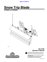
PARTS DIAGRAM AND LIST
A
ITEM PART NO. QTY. DESCRIPTION
62425 1 DOLLY WHEEL ASSY, P PY HW
1 . 62432 1 SUPPORT DR, P PY HW
2 62433
k2430 1 SUPPORT CU, P PY HW
1 DOLLY WHEEL ASSY, S SY
3 . 62435 1 SUPPORT DR, S SY
4 . 62436 1 SUPPORT CU, S SY
The following items are included in both the 62425 and
62430 dolly wheel assemblies.
5 . 62429 2 YOKE
6 . 62423 2 SPRING l-l/8X 2
7 . 62421 2 WHEEL 6X2
8 . 62424 2 SPACER
9 . 91911 2 5/32X l- l/2 COTTER PIN ZYC
10 . 90106 2 1/2-13X3-1/2 HX CS G5 ZP
11 . 91335 2 l/2-13 PT HX LK NUT NYIS ZYC
12 . 91147 2 314 PLAIN WASHER TY A SAE ZYC
13 . 93042 2 3/ 16 LINCHPIN ZYC
14 . 90100 4 1/2-13X1-1/2 HX CS G5 ZYC
15 . 91335 4 l/2- 13 PT HX LK NUT NYIS ZYC
16 . 62437 2 LABEL - INFORMATION (INSTRUCTIONS)
17 . 62447 4 LABEL - INFORMATION (WARNING)
ABBREVIATION KEY
ASSY
CS
cu
Assembly
Cap Screw
Curb-Side
DR
G
HW
HX
LK
NYIS
P
PT
PY
S
SAE
SY
TY
ZP
Driver-Side
Grade
Heavyweight Plow
Hex
Lock
Nylon insert
PRO-PLOW
Prevailing Torque
PRO-PLOW Poly
Standard-Plow
Society of Automotive Engineers
Standard Poly
Type
Zinc Plate
Form No. 13764 3

Form No. 13764
MILWAUKEE, WISCONSIN 53223
aa
A DIVISION OF DOUGLAS DYNAMICS, L.L.C.
4
Printed in the U.S.A.
/