Page is loading ...
Bedienungsanleitung
Operating instructions
Instructions d’emploi
Instrucciones de servicio
Manual de instruções
Istruzioni d’uso
Gebruiksaanwijzing
Betjeningsvejledning
Bruksanvisning
Brukerveiledningen
Käyttöohje
δηγία ειρισµύ
Kullan∂m k∂lavuzu
Deutsch
English
Français
Español
Português
Italiano
Nederlands
Dansk
Svenska
Norsk
Suomi
Eλληvικά
Türkçe
ART ACCUTRIM
F016 L70 348 - Vorderseite Seite 1 Mittwoch, 9. November 2005 2:14 14
2 • F016 L70 348 • 05.09
360°
1
2
3
4
6
10
13
17
5
8
9
11
12
7
14
15
16
F016 L70 348 - U2 Seite 2 Donnerstag, 10. November 2005 9:54 09

3 • F016 L70 348 • 05.09
CLICK!
A
B1
B2
B3
10
8
➊
➋
6
11
11
18
18
19
➊
➋
F016 L70 348 - U3 Seite 3 Donnerstag, 10. November 2005 9:53 09
4 • F016 L70 348 • 05.09
E F
C D
5
3
4
6
➊
➋
➊
➋
22
20
20
21
F016 L70 348 - U4 Seite 3 Donnerstag, 10. November 2005 10:00 10

5 • F016 L70 348 • 05.09
G H
JI
12
➊
➋
➌
6
11
18
6
6
5
7
➊
➋
12
6
F016 L70 348 - U5 Seite 3 Donnerstag, 10. November 2005 9:57 09
6 • F016 L70 348 • 05.09
M
N
K L
9
9
9
F016 L70 348 - U6 Seite 3 Donnerstag, 10. November 2005 9:58 09
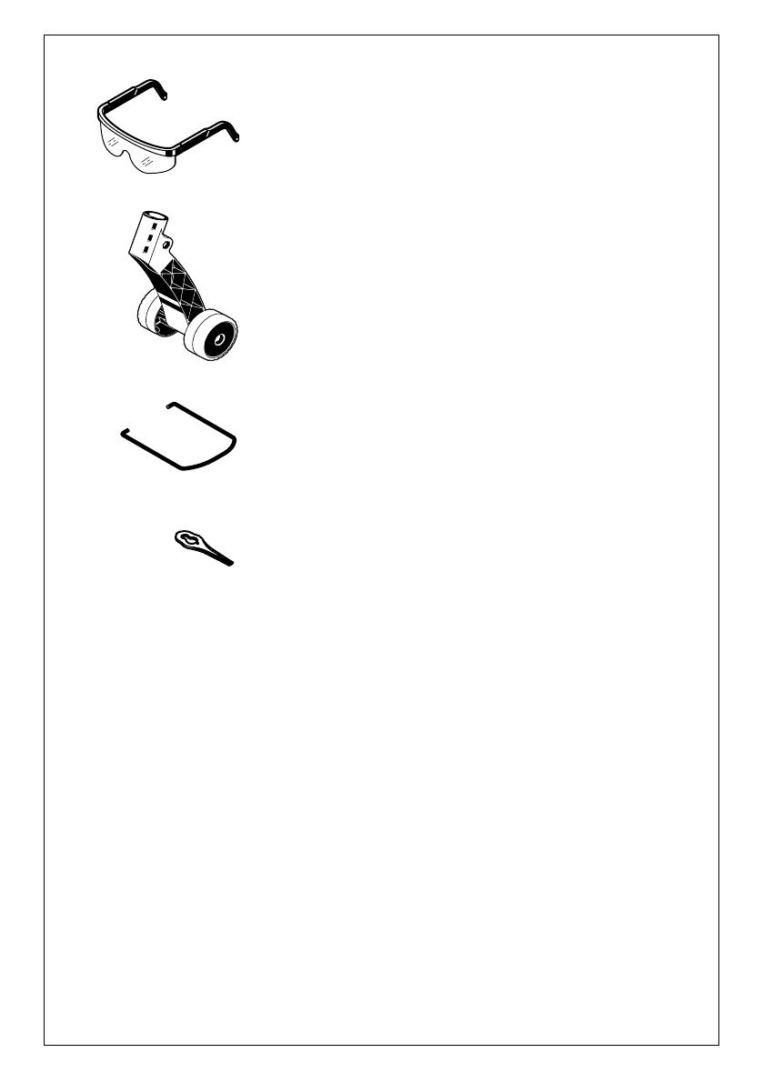
F 016 800 178
F 016 800 172
F 016 800 173
F 016 800 177
(ART 23 ACCUTRIM/
ART 2300 ACCUTRIM)
F 016 800 183
(ART 26 ACCUTRIM/
ART 2600 ACCUTRIM)
7 • F016L70 348 • 05.09
24x
F016 L70 348 - Zubehör Seite 3 Donnerstag, 10. November 2005 9:59 09

Deutsch - 2
Das Gerät ist bestimmt für das Schneiden von Gras
und Unkraut unter Büschen sowie an Böschungen
und Kanten, die mit dem Rasenmäher nicht erreicht
werden können
Der bestimmungsgemäße Gebrauch bezieht sich
auf eine Umgebungstemperatur zwischen 0 °C und
40 °C.
Dieses Handbuch enthält Anweisungen über die
richtige Montage und den sicheren Gebrauch Ihres
Gerätes. Es ist wichtig, dass Sie diese Anweisungen
sorgfältig lesen.
Nehmen Sie den Akku-Rasentrimmer vorsichtig aus
der Verpackung, prüfen Sie, ob die nachfolgenden
Teile vollständig sind:
– Trimmer
– Schutzhaube
– Verstellbarer Griff (montiert)
– Räder (nur ART 26/2600 ACCUTRIM)
– Baum-Schutzbügel
(nur ART 26/2600 ACCUTRIM)
– Schneidteller
– Schneidmesser
– Ladegerät
– Bedienungsanleitung
Wenn Teile fehlen oder beschädigt sind, wenden Sie sich
bitte an Ihren Händler.
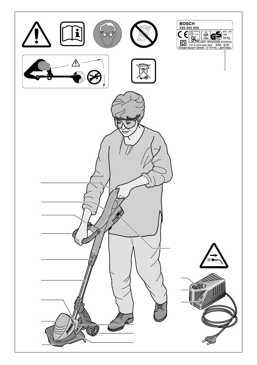
1 Ein-/Ausschalter
2 Griff
3 Griffschraube
4 verstellbarer Griff
5 Klemmhülse
6 Rohr
7 Lüftungsschlitze
8 Trimmerkopf
9 Baum-Schutzbügel
(nur ART 26/2600 ACCUTRIM)
10 Schutzhaube
11 Räder (nur ART 26/2600 ACCUTRIM)
12 Fußpedal für Trimmerkopf-Winkeleinstellung
13 Akku
14 LED-Anzeige
15 Ladegerät
16 Akku-Ladeschacht
17 Seriennummer
Abgebildetes oder beschriebenes Zubehör gehört
teilweise nicht zum Lieferumfang.
Gerätekennwerte
Akku-Rasentrimmer ART 23 ACCUTRIM/
ART 2300 ACCUTRIM
ART 26 ACCUTRIM/
ART 2600 ACCUTRIM
Bestellnummer 3 600 H78 E 3 600 H78 F
Leerlaufdrehzahl [min
-1
] 9 500 9 500
Griff verstellbar ● ●
Winkeleinstellung für Trimmerkopf/Ein-
stellung zum Kantenschneiden ● ●
Schnittdurchmesser [cm] 23 26
Gewicht (ohne Sonderzubehör) [kg] 2,9 2,9
Seriennummer Siehe Seriennummer 17 (Typenschild) an der Maschine.
Akku NiCd NiCd
Bestellnummer 2 607 335 535 2 607 335 535
Nennspannung [V] 18 18
Kapazität [Ah] 1,5 1,5
Ladezeit (Akku entladen) [min] 85 – 120 85 – 120
Ladegerät AL 60 DV 2411 AL 60 DV 2411
Bestellnummer 2 607 224 .. 2 607 224 ..
Ladestrom
– Schnellladevorgang [A] 1,2 1,2
– Erhaltungsladevorgang [mA] 60 60
Zulässiger Ladetemperaturbereich [°C] 0 – 45 0 – 45
Bestimmungsgemäßer
Gebrauch
Einleitung
Lieferumfang
Geräteelemente
F016 L70 348 - Vord…eite.book Seite 2 Mittwoch, 9. November 2005 1:46 13
9 • F016 L70 348 • TMS • 08.09.05
Deutsch - 7
Elektrowerkzeuge, Zubehör und Verpackungen sol-
len einer umweltgerechten Wiederverwertung zuge-
führt werden.
Nur für EU-Länder:
Werfen Sie Elektrowerkzeuge nicht in
den Hausmüll!
Gemäß der Europäischen Richtlinie
2002/96/EG über Elektro- und Elek-
tronik-Altgeräte und ihrer Umsetzung
in nationales Recht müssen nicht
mehr gebrauchsfähige Elektrowerkzeuge getrennt
gesammelt und einer umweltgerechten Wiederver-
wertung zugeführt werden.
Explosionszeichnungen und Informationen zu
Ersatzteilen finden Sie unter:
www.bosch-pt.com
www.powertool-portal.de, das Internetportal für
Heimwerker und Gartenfreunde
www.dha.de, das komplette Service-Angebot der
Deutschen Heimwerker Akademie
Deutschland
Robert Bosch GmbH
Servicezentrum Elektrowerkzeuge
Zur Luhne 2
37589 Kalefeld
✆ Service:........................................... 01 80 - 3 35 54 99
Fax: ............................................... +49 (0) 55 53 / 20 22 37
✆ Kundenberater:........................... 01 80 - 3 33 57 99
Österreich
ABE Service GmbH
Jochen-Rindt-Straße 1
1232 Wien
✆ Service:......................................... +43 (0)1 / 61 03 80
Fax: ................................................... +43 (0)1 / 61 03 84 91
✆ Kundenberater:................. +43 (0)1 / 797 22 3066
E-Mail: [email protected]
Schweiz
✆ Service:..................................... +41 (0)1 / 8 47 16 16
Fax: ..................................................... +41 (0)1 / 8 47 16 57
✆ Kundenberater ................................... 0 800 55 11 55
Luxemburg
✆ Service:......................................... +32 (0)70 / 225565
Fax: ......................................................... +32 (0)70 / 225575
E-Mail: [email protected]
Messwerte ermittelt entsprechend 2000/14/EG
(1,60 m Höhe,1,0 m Abstand) und EN 28 662.
Der A-bewertete Geräuschpegel des Gerätes be-
trägt typischerweise: Schalldruckpegel 72 dB (A);
Schallleistungspegel 88 dB (A).
Die Hand-Arm-Vibration ist typischerweise niedriger
als 2,5 m/s
2
.
Wir erklären in alleiniger Verantwortung, dass die-
ses Produkt mit den folgenden Normen oder norma-
tiven Dokumenten übereinstimmt: EN 786,
EN 60 335 gemäß den Bestimmungen der Richtli-
nien 89/336/EWG, 98/37/EG, 2000/14/EG.
2000/14/EG: Der garantierte Schallleistungspegel
L
WA
ist niedriger als 93 dB (A). Bewertungsverfah-
ren der Konformität gemäß Anhang VI.
Benannte Prüfstelle: SRL, Sudbury England
Benannte Prüfstellen Identifikationsnummer: 1088
Leinfelden, 01.12.2004.
Dr. Egbert Schneider Dr. Eckerhard Strötgen
Senior Vice President Head of Product
Engineering Certification
Robert Bosch GmbH, Power Tools Division
Änderungen vorbehalten
Entsorgung
Kundendienst
Konformitätserklärung
F016 L70 348 - Vord…eite.book Seite 7 Mittwoch, 9. November 2005 1:46 13
14 • F016 L70 348 • TMS • 08.09.05
English - 1
15 • F016 L70 348 • TMS • 08.09.05
Warning! Read these instructions carefully, be
familiar with the controls and the proper use of
the trimmer. Please keep the instructions safe
for later use.
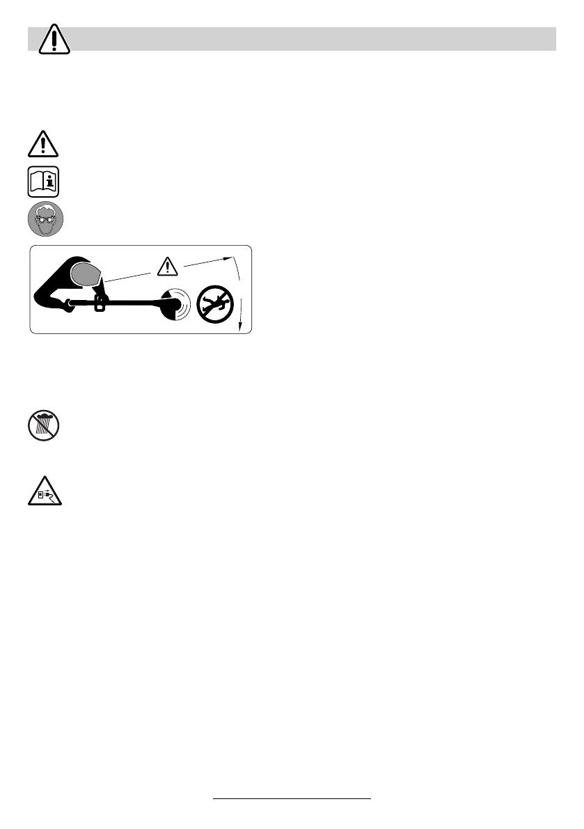
Explanation of symbols on the trimmer
General hazard safety alert.
Read instruction manual.
Wear eye protection.
Beware of thrown or flying objects to bystanders.
Keep bystanders a safe distance away from the ma-
chine.
Remove battery before adjusting or cleaning, and be-
fore leaving the machine unattended for any period.
Do not work in the rain or leave the trimmer
outdoors whilst it is raining.
■ Never operate the trimmer with damaged guards
or shields or without guards or shields in position.
Do not use the charger if the cord is dam-
aged.
■ Before using the machine and after impact, check
for signs of wear or damage and repair if neces-
sary.
■ Do not operate the trimmer when barefoot or
wearing open sandals, always wear substantial
footwear and long trousers.
■ Never allow children or people unfamiliar with
these instructions to use the trimmer. Local regu-
lations may restrict the age of the operator. When
not in use store the trimmer out of reach of chil-
dren.
■ Never work with this trimmer while people, espe-
cially children or pets are nearby.
■ The operator or user is responsible for accidents
or hazards occurring to other people or their prop-
erty.
■ Wait until the blade has completely stopped be-
fore touching it. The blade continues to rotate af-
ter the trimmer is switched off, a rotating blade
can cause injury.
■ Work only in daylight or in good artificial light.
■ Avoid operating the trimmer in wet grass, where
feasible.
■ Switch off when transporting the trimmer to and
from the area to be worked on.
■ Switch on the trimmer with hands and feet well
away from the rotating line.
■ Do not put hands or feet near the rotating blade.
■ Never fit metal cutting elements to this trimmer.
■ Inspect and maintain the trimmer regularly.
■ Have the trimmer repaired only by an authorized
customer service agent.
■ Always ensure that the ventilation slots are kept
clear of debris.
■ Switch off and remove battery from the trimmer:
– whenever you leave the machine unattended for
any period
– before replacing the blade
– before cleaning or working on the trimmer.
■ Store the machine in a secure dry place out of
reach of children. Do not place other objects on
top of the machine.
■ Replace worn or damaged parts for safety.
■ Ensure replacement parts fitted are Bosch ap-
proved.
■ Ensure the switch is in the off position before in-
serting battery pack. Inserting the battery pack
into machines that have the switch on invites ac-
cidents.
■ Recharge only with the charger specified by the
manufacturer. A charger that is suitable for one
type of battery pack may create a risk of fire when
used with another battery pack.
■ Use machines only with specifically designated
battery packs. Use of any other battery packs
may create a risk of injury and fire.
■ When battery pack is not in use, keep it away
from other metal objects like paper clips, coins,
keys, nails, screws, or other small metal objects
that can make a connection from one terminal to
another. Shorting the battery terminals together
may cause burns or a fire.
■ Under abusive conditions, liquid may be ejected
from the battery; avoid contact. If contact acci-
dentally occurs, flush with water. If liquid contacts
eyes, additionally seek medical help. Liquid
ejected from the battery may cause irritation or
burns.
Safety Notes
360°
F016 L70 348 - GB Seite 1 Donnerstag, 10. November 2005 10:11 10

English - 2
16 • F016 L70 348 • TMS • 08.09.05
The product is intended for the cutting of grass and
weeds under bushes, as well as on slopes and
edges that can not be reached with the lawn mower.
Intended Use is related to operation within 0 °C and
40 °C ambient temperature.
This manual gives instructions on the correct as-
sembly and safe use of your machine. It is important
that you read these instructions carefully.
Carefully remove the machine from its packaging
and check that you have all the following items:
– Trimmer
– Cutting guard
– Adjustable handle (fitted)
– Wheels (ART 26/2600 ACCUTRIM only)
– Plant protector (ART 26/2600 ACCUTRIM only)
– Cutting disc
– Blades
– Battery charger
– Operating instructions
When parts are missing or damaged, please contact your
dealer.
1 On/Off switch
2 Handle
3 Handle wing nut
4 Adjustable handle
5 Adjusting collar
6 Shaft
7 Ventilation slots
8 Trimmer head
9 Plant protector (ART 26/2600 ACCUTRIM only)
10 Cutting guard
11 Wheels (ART 26/2600 ACCUTRIM only)
12 Foot pedal for head angle adjustment
13 Battery
14 LED indicator
15 Battery charger
16 Battery charging compartment
17 Serial Number
Not all of the accessories illustrated or described are
included as standard delivery.
Product Specification
Trimmer ART 23 ACCUTRIM/
ART 2300 ACCUTRIM
ART 26 ACCUTRIM/
ART 2600 ACCUTRIM
Part number 3 600 H78 E 3 600 H78 F
No-load speed [rpm] 9 500 9 500
Adjustable handle ● ●
Cutting Head angle adjustment/edging
adjustment ● ●
Cutting circle [cm] 23 26
Weight (without optional extras) [kg] 2.9 2.9
Serial Number See serial No 17 (rating plate) on machine.
Battery type NiCd NiCd
Part number 2 607 335 535 2 607 335 535
Nominal Voltage [V] 18 18
Capacity [Ah] 1.5 1.5
Charging time (empty battery) [min] 85 – 120 85 – 120
Battery charger AL 60 DV 2411 AL 60 DV 2411
Part number 2 607 224 .. 2 607 224 ..
Charging current
– Rapid charging [A] 1.2 1.2
– Trickle charging [mA] 60 60
Allowable charging temperature range [°C] 0 – 45 0 – 45
Intended Use
Introduction
Delivered Items
Operating Controls
F016 L70 348 - GB Seite 2 Donnerstag, 10. November 2005 10:11 10
English - 3
17 • F016 L70 348 • TMS • 08.09.05
Charging Procedure
The charging procedure starts as soon as the mains
plug is plugged into the socket and the battery 13 is
inserted into the charging compartment 16.
Due to the intelligent charging method, the charging
condition of the battery is automatically detected and
the battery is charged depending on battery temper-
ature and voltage.
This gives longer life to the battery and always
leaves it fully charged when kept in the charger for
storage.
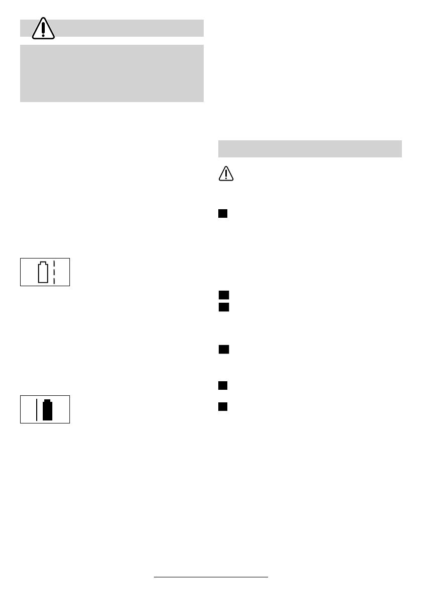
Control of the charging procedure is indicated via
the charge control LED 14:
Rapid charging
The rapid-charging procedure is in-
dicated by flashing of the charge
control LED 14.
The battery is fully charged as soon as the LED 4
switches from flashing to being lit continuously. Af-
terwards the battery can be removed for immediate
use.
It is recommended not to remove the battery until the
battery is fully charged.
☞
The rapid-charging procedure is possible only
when the temperature of the battery is be-
tween 0 °C and 45 °C.
Trickle charging
The trickle-charging procedure is in-
dicated by continuous lighting of
the LED 4.
With the battery fully charged, the charger immedi-
ately switches to trickle-charge mode. This equal-
izes the natural running-down of the battery again.
Charging Advice
With continuous or several repetitive charging cy-
cles without interruption, the charger can warm up.
This is not harmful and does not indicate a technical
defect of the unit.
A battery that is new or has not been used for a
longer period does not develop its full capacity until
after approximately 5 charging/discharging cycles.
A significantly reduced working period after charging
indicates that the batteries are worn out and must be
replaced.
Do not connect the battery before product
is completely assembled.
Ensure product is assemble in the following or-
der:
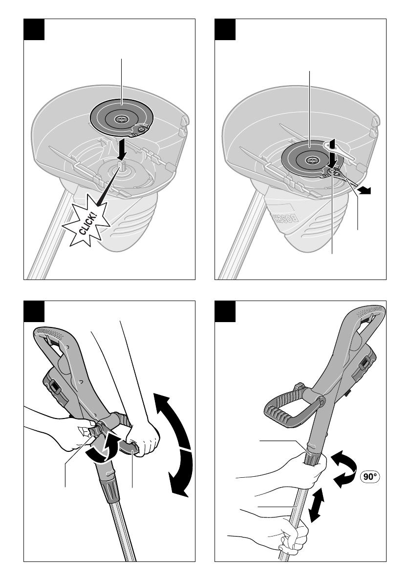
Mounting the Cutting Guard
Place the cutting guard 10 on the trimmer head 8.
➊ Hook the guard onto trimmer head and push until
secure fitting.
➋ Push rear of guard until secure (click).
Mounting the Wheels (ART 26/2600 ACCUTRIM
only)
Fit the wheels 11 onto the shaft 6.
Fit the bolt 19 and the wingnut 18.
Note: The position of the wheels can be adjusted by
loosening the wingnut 18 and moving to the desired
position.
The wheels can be moved up and down the
shaft 6 depending on the height of cut required.
Fitting Cutting Disc/Fitting Blade
Press cutting disc 20 onto drive adaptor as
shown (click).
Fit the blade, place the blade 22 over the
pivot 21 and pull outwards until it snaps into place.
For Your Safety
Warning! Switch off, remove battery from ma-
chine before adjusting or cleaning.
The blade continues to rotate for a few sec-
onds after the trimmer is switched off.
Caution – do not touch rotating blade.
Assembly
A
B1
B2
B3
C
D
F016 L70 348 - GB Seite 3 Donnerstag, 10. November 2005 10:11 10
English - 4
18 • F016 L70 348 • TMS • 08.09.05
Using Adjustable Handle
The adjustable handle 4 can be set in various posi-
tions:
➊ To change the position undo the handle wing
nut 3 and move the adjustable handle 4.
➋ Tighten the handle wing nut 3 securely to fix the
adjustable handle 4 in the adjusted position.
Adjusting Product Length
➊ Loosen the adjustment collar 5 90°.
➋ Pull the shaft out to increase the height, or push
the shaft in to decrease the height. Re-tighten ad-
justment collar 5.
Adjusting cutting head angle:
To change the angle depress the foot pedal 12 and
move the shaft 6 to the desired position.
Release the foot pedal 12.
Adjusting for Edging Mode
Moving wheels (where fitted):
➊ Loosen wingnut 18.
➋ Twist wheels 11 90° as shown.
➌ Tighten wingnut 18.
Adjusting cutting head angle:
➊ Depress the foot pedal 12.
➋ Move the shaft 6 to the lowest position. Release
the foot pedal 12.
Move trimmer head:
➊ Loosen the adjustment collar 5.
➋ Turn the shaft 6 90° to position the trimmer
head 8 for trimming/edging as shown. Re-tighten
adjustment collar 5.
Remove stones, loose pieces of wood and
other objects from the cutting area.
The blade continues to rotate for a few seconds
after the trimmer is switched off. Allow the mo-
tor/blade to stop rotating before switching “on”
again.
Do not rapidly switch off and on.
Switching On and Off
Press switch 1 and hold depressed. Release
switch 1 for switching off.
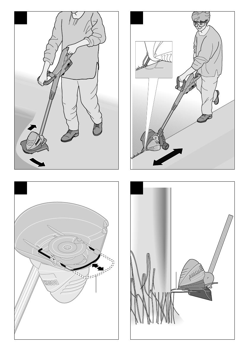
Cutting Grass
Move the trimmer left and right, keeping it well away
from the body.
The trimmer can efficiently cut grass up to a height
of 15 cm. Cut taller grass in stages.
Remove the wheels when cutting long grass
(ART 26/2600 ACCUTRIM only).
Trimming Edges
Guide the trimmer along the edge of the lawn. Do
not allow the cutting line to contact paved surfaces,
stones or garden walls, since this will wear the blade
rapidly.
For better control use the plant protector 9 (ART
26/2600 ACCUTRIM only – available as an acces-
sory for ART 23/2300 ACCUTRIM) as a guide.
Cutting Around Trees and Bushes
Carefully cut around trees and bushes so that they
do not come into contact with the cutting line.
Plants can die if you damage the bark.
For better control use adjustable handle 4 and
use the plant protector 9 (ART 26/2600 ACCUTRIM
only – available as an accessory for ART 26/2600
ACCUTRIM).
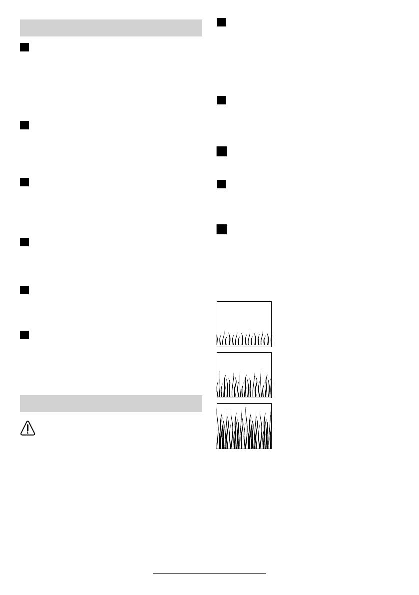
Battery duration
Battery duration is dependent on the wortking condi-
tions:
light conditions:
up to 800 metres
medium conditions:
up to 350 metres
tough conditions:
up to 60 metres
Adjustment
Cutting and Edging
E
F
G
H
I
J
K
L
M
N
M
F016 L70 348 - GB Seite 4 Donnerstag, 10. November 2005 10:11 10

English - 5
19 • F016 L70 348 • TMS • 08.09.05
Before any work on the machine itself, re-
move battery from machine.
Note: To ensure long and reliable service, carry out
the following maintenance regularly.
Regularly check for obvious defects such as loose
fixings, and worn or damaged components.
Check that covers and guards are undamaged and
correctly fitted. Carry out necessary maintenance or
repairs before using.
If the trimmer should happen to fail despite the care
taken in manufacture and testing, repair should be
carried out by an authorized customer service agent
for Bosch garden products.
For all correspondence and spare parts orders, al-
ways include the 10-digit part number (TYP) from
the nameplate of the machine!
Before any work on the machine itself, re-
move battery from machine.
To remove the worn blade 22 push in direction of the
arrow until it snaps off the pivot 21.
Clean the pivot 21 of any residual plastic/debris with
a sharp knife.
To refit the new blade 22 place the eyelet over the
pivot 21 and pull outwards until it snaps into place.
Note: Only use Bosch replacement blades. They
have been developed specially for improved cutting
performance. The use of other cutter blades will lead
to a deterioration in performance and possible dam-
age to the product.
Stop and remove battery from product. En-
sure battery is removed before storage.
Clean the exterior of the machine thoroughly using a
soft brush and cloth. Do not use water, solvents or
polishes. Remove all grass and debris, especially
from the ventilation slots 7.
Turn the machine on its side and clean the cutting
guard 10 inside. If grass cuttings are compacted, re-
move with a wooden or plastic implement.
Battery should be stored between 0 – 45 °C; incor-
rect storage could result in the battery being dam-
aged.
Maintenance
Blade Maintenance
D
After Trimming/Storage
F016 L70 348 - GB Seite 5 Donnerstag, 10. November 2005 10:11 10

English - 6
20 • F016 L70 348 • TMS • 08.09.05
The following table gives checks and actions that you can perform if your machine does not operate correctly.
If these do not identify/remedy the problem, contact your service agent.
Warning: Switch off and remove battery before investigating fault.
Fault Finding
Symptom Possible Cause Remedy
Can not fit Guard over
cutting disc
Incorrect assembly Remove cutting disc and fit guard, see
also Product assembly
Machine fails to operate Battery discharged Recharge battery, see also Charging
advice
Machine functions
intermittently
Machines internal wiring damaged
On/Off switch defective
Contact Service Agent
Contact Service Agent
Excessive vibration/
noise
Machine fault
Blade broken
Contact Service Agent
Replace blade
Cutting time low on one
battery charge
Battery not used for long period or ini-
tial usage
Grass too high
Battery worn out
Fully charge battery, see also charging
advice
Cut in stages
Replace the battery
Blade will not move Battery discharged
Machine fault
Recharge battery, see also Charging
advice
Contact Service Agent
Machine is not cutting Blade broken
Battery not fully charged
Grass entangled around cutting disc
Replace blade
Recharge battery, see also Charging
advice
Remove grass
No charging procedure
possible due to defective
battery
The battery temperature is not within
the allowable temperature range
The contacts of the battery are con-
taminated
The battery is defective, due to a dis-
connection in the battery (individual
cells)
Get the battery temperature within the
allowable temperaturerange (0 °C to
45 °C) either by cooling down or warm-
ing up. As soon as the battery temper-
ature is within the allowable tempera-
ture range again, the battery charger
automatically switches to rapid charg-
ing
Corrective measure: Clean the con-
tacts (e. g. by inserting and removing
the battery several times) or replace
the battery, as required
Replace the battery
The LED indicator 14
does not light up after
plugging the mains plug
into the socket and insert-
ing the battery into the
charging compartment 16
The charger plug is not inserted (prop-
erly)
Socket, cable or charger are defective
Insert the plug (fully) into the socket
Check the mains voltage and if neces-
sary, have the battery charger
checked by an authorized customer
service station for Bosch power tools
F016 L70 348 - GB Seite 6 Donnerstag, 10. November 2005 10:11 10
English - 7
21 • F016 L70 348 • TMS • 08.09.05
Power tools, accessories and packaging should be
sorted for environmental-friendly recycling.
Only for EC countries:
Do not dispose of power tools into
household waste!
According to the European Directive
2002/96/EC on waste electrical and
electronic equipment and its incorpo-
ration into national law, power tools
that are no longer suitable for use must be sepa-
rately collected and sent for recovery in an environ-
mental-friendly manner.
Exploded views and information on spare parts
can be found under:
www.bosch-pt.com
Great Britain
Robert Bosch Ltd. (B.S.C.)
P.O. Box 98
Broadwater Park
North Orbital Road
Denham-Uxbridge
Middlesex UB 9 5HJ
✆ Service ................................ +44 (0) 18 95 / 83 87 82
Fax Service ............................... +44 (0) 18 95 / 83 87 89
✆ Advice line......................... +44 (0) 18 95 / 83 87 91
Fax Advice................................. +44 (0) 18 95 / 83 87 93
Ireland
Beaver Distribution Ltd.
Greenhills Road
Tallaght-Dublin 24
✆ Service .................................... +353 (0)1 / 4 14 94 00
Fax .................................................... +353 (0)1 / 4 59 80 30
Australia and New Zealand
Robert Bosch Australia Pty. Ltd.
RBAU/SPT
1555 Centre Road
P.O. Box 66
3168 Clayton/Victoria
✆ ................................................ +61 (0)1 / 3 00 30 70 44
Fax ................................................ +61 (0)1 / 3 00 30 70 45
www.bosch.com.au
Measured values determined according to 2000/14/
EC (1.60 m height, 1.0 m distance away) and
EN 28 662.
Typically the A-weighted noise level of the product
is: sound pressure level 72 dB (A); sound power
level 88 dB (A).
The typical hand/arm vibration is below 2.5 m/s
2
.
We declare under our sole responsibility that this
product is in conformity with the following standards
or standardization documents: EN 786, EN 60 335
according to the provisions of the directives 89/336/
EEC, 98/37/EC, 2000/14/EC.
2000/14/EC: The guaranteed sound power level
L
WA
is lower than 93 dB (A). Conformity assess-
ment procedure according to Annex VI.
Notified body: SRL, Sudbury England
Notified body identifications number: 1088
Leinfelden, 01.12.2004.
Dr. Egbert Schneider Dr. Eckerhard Strötgen
Senior Vice President Head of Product
Engineering Certification
Robert Bosch GmbH, Power Tools Division
Subject to change without notice
Disposal
Service
Declaration of Conformity
F016 L70 348 - GB Seite 7 Donnerstag, 10. November 2005 10:11 10
Français - 7
Les outils électroportatifs, ainsi que leurs accessoi-
res et emballages, doivent pouvoir suivre chacun
une voie de recyclage appropriée.
Seulement pour les pays de l’Union Euro-
péenne :
Ne pas jeter les appareils électropor-
tatifs avec les ordures ménagères !
Conformément à la directive euro-
péenne 2002/96/CE relative aux dé-
chets d’équipements électriques et
électroniques et sa réalisation dans
les lois nationales, les outils électroportatifs dont on
ne peut plus se servir doivent être séparés et suivre
une voie de recyclage appropriée.
Vous trouverez des vues éclatées ainsi que des
informations concernant les pièces de rechange
sous :
www.bosch-pt.com
France
Robert Bosch France S.A.S.
Service Après-vente/Outillage
126, rue de Stalingrad
93700 Drancy
✆ Centre d’appels SAV :....................... 0143 11 9006
N° vert Conseiller Bosch : ............ 0 800 05 50 51
Belgique
✆ .......................................................... +32 (0)70 / 225565
Fax .......................................................... +32 (0)70 / 225575
E-Mail : [email protected]
Suisse
✆ ...................................................... +41 (0)1 / 8 47 16 16
Fax ...................................................... +41 (0)1 / 8 47 16 57
✆ Service conseil client ...................... 0 800 55 11 55
Valeurs de mesures obtenues conformément à la
2000/14/CE (mesure effectuée à une hauteur de
1,60 m et à 1,0 m de distance) et EN 28 662.
Les mesures réelles (A) des niveaux sonores de la
machine sont : intensité de bruit 72 dB (A). Niveau
de bruit 88 dB (A).
La vibration de l’avant-bras est en-dessous de
2,5 m/s
2
.
Nous déclarons sous notre propre responsabilité
que ce produit est en conformité avec les normes ou
documents normalisés suivants : EN 786,
EN 60 335 conformément aux réglementations
89/336/CEE, 98/37/CE, 2000/14/CE.
2000/14/CE : Le niveau d’intensité acoustique L
WA
garanti est inférieur à 93 dB (A). Procédures d’éva-
luation de la conformité conformément à l’an-
nexe VI.
Office de contrôle désigné : SRL, Sudbury England
Numéro d’identification de l’office de contrôle dési-
gné : 1088
Leinfelden, 01.12.2004.
Dr. Egbert Schneider Dr. Eckerhard Strötgen
Senior Vice President Head of Product
Engineering Certification
Robert Bosch GmbH, Power Tools Division
Sous réserve de modifications
Elimination de déchets
Service après-vente
Déclaration de conformité
F016 L70 348 - Vord…eite.book Seite 7 Mittwoch, 9. November 2005 1:46 13
28 • F016 L70 348 • TMS • 08.09.05
Español - 7
Recomendamos que las herramientas eléctricas,
accesorios y embalajes sean sometidos a un pro-
ceso de recuperación que respete el medio am-
biente.
Sólo para países de la UE:
¡No arroje las herramientas eléctricas
a la basura!
Conforme a la Directriz Europea
2002/96/CE sobre aparatos eléctri-
cos y electrónicos inservibles, tras su
conversión en ley nacional, deberán
acumularse por separado las herramientas eléctri-
cas para ser sometidas a un reciclaje ecológico.
Los dibujos de despiece e informaciones sobre
las piezas de repuesto las encontrará en internet
bajo:
www.bosch-pt.com
España
Robert Bosch España, S.A.
Departamento de ventas
Herramientas Eléctricas
C/Hermanos García Noblejas, 19
28037 Madrid
✆ Asesoramiento al cliente.......... +34 901 11 66 97
Fax .............................................................. +34 91 327 98 63
Venezuela
Robert Bosch S.A.
Final Calle Vargas. Edf. Centro Berimer P.B.
Boleita Norte
Caracas 107
✆ ........................................................ +58 (0)2 / 207 45 11
México
Robert Bosch S.A. de C.V.
✆ Interior................................. +52 (0)1 / 800 627 1286
✆ D.F............................................ +52 (0)1 / 52 84 30 62
E-Mail: [email protected]
Argentina
Robert Bosch Argentina S.A.
Córdoba 5160
1414 Buenos Aires (Capital Federal)
Atención al Cliente
✆ .................................................... +54 (0)810 / 555 2020
E-Mail: [email protected]
Perú
Autorex Peruana S.A.
República de Panamá 4045,
Lima 34
✆ ......................................................... +51 (0)1 / 475-5453
E-Mail: [email protected]
Chile
EMASA S.A.
Irarrázaval 259 – Ñuñoa
Santiago
✆ ......................................................... +56 (0)2 / 520 3100
E-Mail: [email protected]
Determinación de los valores de medición según
norma 2000/14/CE (a 1,60 m de altura y 1,0 m de
distancia) y EN 28 662.
El nivel de ruido típico de la máquina corresponde a:
nivel de presión de sonido 72 dB (A); nivel de poten-
cia de sonido 88 dB (A).
El nivel de vibraciones típico en la mano/brazo es
menor de 2,5 m/s
2
.
Declaramos bajo nuestra sola responsabilidad que
este producto está en conformidad con las normas
o documentos normalizados siguientes: EN 786,
EN 60 335 de acuerdo con las regulaciones
89/336/CEE, 98/37/CE, 2000/14/CE.
2000/14/CE: El nivel de potencia acústica L
WA
que
se garantiza, es inferior a 93 dB (A). Procedimiento
para evaluación de la conformidad según apén-
dice VI.
Servicio de inspección designado: SRL, Sudbury
England
Nº de identificación del servicio de inspección desig-
nado: 1088
Leinfelden, 01.12.2004.
Dr. Egbert Schneider Dr. Eckerhard Strötgen
Senior Vice President Head of Product
Engineering Certification
Robert Bosch GmbH, Power Tools Division
Reservado el derecho de modificaciones
Eliminación
Servicio de asistencia técnica Declaración de conformidad
F016 L70 348 - Vord…eite.book Seite 7 Mittwoch, 9. November 2005 1:46 13
35 • F016 L70 348 • TMS • 08.09.05

Português - 7
Ferramentas eléctricas, acessórios e embalagens
devem ser enviados a uma reciclagem ecológica de
matérias primas.
Só países da União Europeia:
Não deitar ferramentas eléctricas no
lixo doméstico!
De acordo com a directiva européia
2002/96/CE para aparelhos eléctri-
cos e electrónicos velhos, e com as
respectivas realizações nas leis naci-
onais, as ferramentas eléctricas que não servem
mais para a utilização, devem ser enviadas separa-
damente a uma reciclagem ecológica.
Desenhos e informações a respeito das peças
sobressalentes encontram-se em:
www.bosch-pt.com
Portugal
Robert Bosch LDA
Avenida Infante D. Henrique
Lotes 2E-3E
1800 Lisboa
✆ ....................................................... +351 21 / 8 50 00 00
Fax ....................................................... +351 21 / 8 51 10 96
Brasil
Robert Bosch Ltda.
Caixa postal 1195
13065-900 Campinas
✆ ................................................................ 0800 / 70 45446
E-Mail: [email protected]
Valores de medida de acordo com 2000/14/CE (al-
tura 1,60 m, distância 1,0 m) e EN 28 662.
O nível de ruído avaliado A do aparelho é tipica-
mente: Nível de pressão acústica 72 dB (A). Nível
de potência acústica 88 dB (A).
A vibração do braço e da mão é tipicamente inferior
a 2,5 m/s
2
.
Declaramos sob nossa exclusiva responsabilidade
que este producto cumpre as seguintes normas ou
documentos normativos: EN 786, EN 60 335 con-
forme as disposições das directivas 89/336/CEE,
98/37/CE, 2000/14/CE.
2000/14/CE: O nível garantido de potência acús-
tica L
WA
é inferior a 93 dB (A). Processo de avalia-
ção da conformidade conforme anexo VI.
Posto de teste mencionado: SRL, Sudbury England
Número de identificação de entidade de inspecção
mencionada: 1088
Leinfelden, 01.12.2004.
Dr. Egbert Schneider Dr. Eckerhard Strötgen
Senior Vice President Head of Product
Engineering Certification
Robert Bosch GmbH, Power Tools Division
Reservado o direito a modificações
Eliminação
Serviço ao cliente
Declaração de conformidade
F016 L70 348 - Vord…eite.book Seite 7 Mittwoch, 9. November 2005 1:46 13
42 • F016 L70 348 • TMS • 08.09.05

Italiano - 2
L’utensile è idoneo per tagliare erba ed erbacce
sotto cespugli nonché su scarpate e bordi non ac-
cessibili al tosaerba.
L’uso corretto si riferisce ad una temperatura am-
bientale tra 0 °C e 40 °C.
Il presente manuale fornisce le istruzioni necessarie
per un corretto assemblaggio ed un utilizzo sicuro
della Vostra macchina. È importante leggere atten-
tamente le presenti istruzioni.
Estrarre il tosaerba a batteria con attenzione dall’im-
ballaggio ed accertarsi che tutte le componenti che
seguono facciano parte della fornitura:
– Tosaerba a filo
– Calotta di protezione
– Impugnatura regolabile (montata)
– Ruote (solo ART 26/2600 ACCUTRIM)
– Staffa di protezione per piante
(solo ART 26/2600 ACCUTRIM)
– Disco portalama
– Lama di taglio
– Stazione di ricarica
– Manuale di istruzioni
In caso che un qualsiasi elemento dovesse mancare oppure
dovesse essere danneggiato, mettersi in contatto con il ri-
venditore presso il quale avete acquistato la macchina.
1 Interruttore di avvio/arresto
2 Impugnatura
3 Vite dell’impugnatura
4 Impugnatura regolabile
5 Bussola di fissaggio
6 Tubo
7 Feritoie di ventilazione
8 Testa del tosaerba a filo
9 Staffa di protezione per piante
(solo ART 26/2600 ACCUTRIM)
10 Calotta di protezione
11 Rotelle (solo ART 26/2600 ACCUTRIM)
12 Pedale per la regolazione dell’angolo della te-
sta del tosaerba a filo
13 Batteria
14 Spia LED
15 Stazione di ricarica
16 Sede di ricarica della batteria
17 Numero di serie
Gli accessori illustrati o descritti nelle istruzioni per
l’uso non sono sempre compresi nella fornitura!
Dati tecnici
Tosaerba a batteria ART 23 ACCUTRIM/
ART 2300 ACCUTRIM
ART 26 ACCUTRIM/
ART 2600 ACCUTRIM
Codice di ordinazione 3 600 H78 E 3 600 H78 F
Numero di giri a vuoto [g/min] 9 500 9 500
Impugnatura regolabile ● ●
Regolazione dell’angolo per testa del tosa-
erba a filo/Regolazione per il taglio di margini ● ●
Diametro del taglio [cm] 23 26
Peso (senza accessori speciali) [kg] 2,9 2,9
Numero di serie Cfr. numero di serie 17 (targhetta di costruzione) applicata
alla macchina.
Batteria ricaricabile NiCd NiCd
Codice di ordinazione 2 607 335 535 2 607 335 535
Tensione nominale [V] 18 18
Autonomia [Ah] 1,5 1,5
Tempo di ricarica (a batteria scarica) [min] 85 – 120 85 – 120
Stazione di ricarica AL 60 DV 2411 AL 60 DV 2411
Codice di ordinazione 2 607 224 .. 2 607 224 ..
Corrente di ricarica
– Operazione veloce di ricarica [A] 1,2 1,2
– Operazione di ricarica di mantenimento [mA] 60 60
Campo ammesso di temperatura di ricarica [°C] 0 – 45 0 – 45
Uso conforme alle norme
Introduzione
Volume di fornitura
Elementi della macchina
F016 L70 348 - Vord…eite.book Seite 2 Mittwoch, 9. November 2005 1:46 13
44 • F016 L70 348 • TMS • 08.09.05
/