ESAB R-5007 User manual

Type
User manual

ESAB R-5007, a single-stage regulator/flowmeter, precisely manages and measures the flow of various gases, including argon, helium, carbon dioxide, nitrogen, and C-25 (75% argon - 25% CO2), for a wide range of applications. Calibrated for flow ranges from 10 to 80 cubic feet per hour (cfh) or 5 to 38 liters per minute (L/min), it offers accurate flow control. With its easy-to-read flowmeter tube and adjustable flow control valve, you can precisely set and monitor the desired gas flow rate for welding, cutting, or gouging processes.

ESAB R-5007, a single-stage regulator/flowmeter, precisely manages and measures the flow of various gases, including argon, helium, carbon dioxide, nitrogen, and C-25 (75% argon - 25% CO2), for a wide range of applications. Calibrated for flow ranges from 10 to 80 cubic feet per hour (cfh) or 5 to 38 liters per minute (L/min), it offers accurate flow control. With its easy-to-read flowmeter tube and adjustable flow control valve, you can precisely set and monitor the desired gas flow rate for welding, cutting, or gouging processes.

OPERATING INSTRUCTIONS for
F-11-273-N
September, 1997
R-502, R-5007, R-5008
REGULATOR/FLOWMETERS
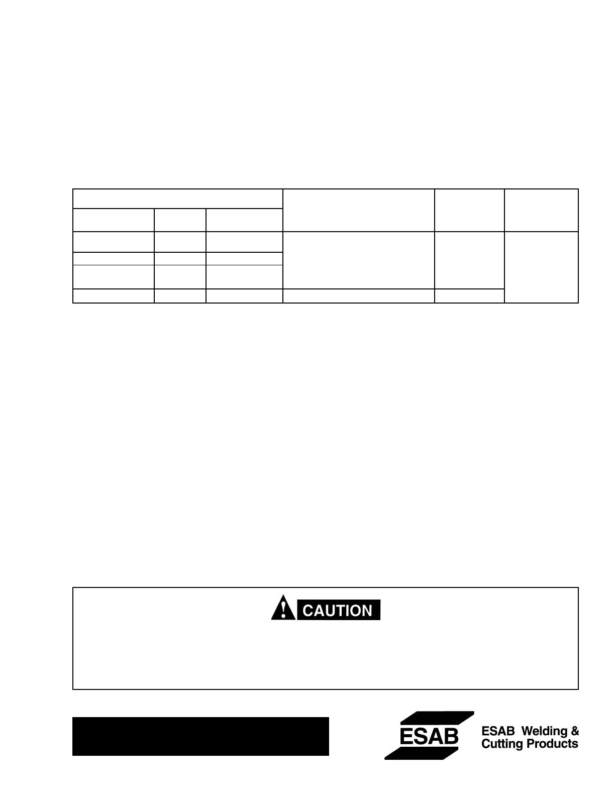
Regulator Gas Service & Inlet Outlet
Calibrated Flow Range, Connection, Connection
Model Part No. Construction cfh (L/min) CGA No. CGA No.
R-502 998846 Two-Stage Argon: 10 - 70 (5 - 33) 580
R-502-FM-680 19018 Two-Stage Helium 20 - 220 (0 - 103) 680 032
C-25*: 10 - 65 (5 - 31) (5/8 ¾18),
R-5007 998124 Single-Stage Nitrogen: 10 - 80 (5 - 38) 580 R.H. Fem.)
R-5008 998125 Single-Stage Carbon Dioxide: 10 - 85 (5 - 40) 320
*75% Argon - 25% CO
2
Mixture
TO CONNECT
1. Open the cylinder valve slightly, for an instant, to
blow out any dust or dirt that may have collected in
the valve outlet. Be sure to keep your face away
from the valve outlet to protect your eyes.
2. Attach the regulator to the cylinder valve, and
tighten the connection nut with a wrench. (Do not
use the flowmeter tube as a handle attaching the
regulator.)
3. Make sure that the flow control valve on the flow-
meter is closed.
4. Open the cylinder valve SLOWLY.
5. Attach hose to the flowmeter outlet and to the equip-
ment with which the gas is to be used. Tighten the
connecting nuts with a wrench.
TO REGULATE FLOW
Flow is controlled by adjusting the flowmeter valve un-
til the desired flow is indicated by the ball float in the
flowmeter tube. Always take the reading across the TOP
of the ball. The outer flowmeter tube (square) can be
rotated by hand to bring the desired scale into position
for convenient reading. Scales for argon, helium, car-
bon dioxide, nitrogen, and C-25 mixture (75 per cent
argon, 25 per cent carbon dioxide) are provided. For
other gas mixtures, consult your gas supplier for the
conversion factor to apply to the reading indicated on
one of the scales. All scales indicate flow in terms of
cubic feet per hour (cfh). The flow readings are accu-
rate within +/- 5% of the maximum calibrated scale
reading for each gas. To convert to liters per minute
(L/min) multiply scale reading by 0.47.
Be sure this information reaches the operator.
You can get extra copies through your supplier.
These INSTRUCTIONS are for experienced operators. If you are not fully familiar with the principles of operation
and safe practices for arc welding equipment, we urge you to read our booklet, Precautions and Safe Practices
for Arc Welding, Cutting, and Gouging, Form 52-529. Do NOT permit untrained persons to install, operate, or
maintain this equipment. Do NOT attempt to install or operate this equipment until you have read and fully under-
stand these instructions. If you do not fully understand these instructions, contact your supplier.
TO STOP WORK:
When work is to be stopped for a half-hour or more, or
before disconnecting the regulator from a cylinder, do
the following:
1. Close the cylinder valve.
2. Open flowmeter valve and valve downstream al-
lowing the trapped gas to flow out.
3. When the gauge and ball float drop to zero, close
the flowmeter valve.
INLET MAINTENANCE:
This regulator is equipped with a porous metal inlet
filter, P/N 71Z33, pressed into the regulator inlet nipple.
No regulator should be connected to a cylinder valve
unless it contains this filter. You can replace the filter if
you have reason to do so. To remove a filter, insert a
No. 1 EZY-OUT or a No. 6 wood screw (about 2-in.
long) into the filter and pull it out. Press the new filter
into the nipple with a 1/4-in. round metal rod.
REPAIR SERVICE
Regulators in need of repair should be returned to your
ESAB welding distributor or to ESAB Remanufacturing
Center, Ebenezer Road, Florence, SC.
If you have your own properly equipped and staffed
repair facility, a repair parts booklet for this regulator is
available on request to your distributor. Request F-14-
353.
NOTE: Safety release device equipped on oxygen
and inert gas regulators is designed for regu-
lator protection; not for hose or equipment
downstream. If gas escapes through the safety
release device, immediately close cylinder
valve, and then remove regulator from service
for repair.
F-11-273-N 9/97 3M Printed in U.S.A.
  • Page 1 1
  • Page 2 2

ESAB R-5007 User manual

Type
User manual

ESAB R-5007, a single-stage regulator/flowmeter, precisely manages and measures the flow of various gases, including argon, helium, carbon dioxide, nitrogen, and C-25 (75% argon - 25% CO2), for a wide range of applications. Calibrated for flow ranges from 10 to 80 cubic feet per hour (cfh) or 5 to 38 liters per minute (L/min), it offers accurate flow control. With its easy-to-read flowmeter tube and adjustable flow control valve, you can precisely set and monitor the desired gas flow rate for welding, cutting, or gouging processes.

Ask a question and I''ll find the answer in the document

Finding information in a document is now easier with AI