Page is loading ...

Form P7166
Edition 4
April 2007
CCN: 03540697
Save These Instructions
Turbine Powered Starters
Series TS1401
Installation and Maintenance
Information

2 03540697_ed4
WARNING
General Product Safety Information
Read and understand this manual before operating this starter.
It is your responsibility to make this safety information available to others that will operate this starter.
Failure to observe the following warnings could result in injury.
WARNING
For safety, top performance, and maximum durability of parts, do not operate Series TS1401 Starter at air pressures over the
pressure rating stamped on the nameplate. Use supply lines of adequate size as directed in the installation instructions in this
manual.
Always turn o the air or gas supply and disconnect the air or gas supply hose before installing, removing or adjusting any
accessory on this starter, or before performing any maintenance on this starter.
Series TS1401 Starter are designed for gas operation. They are not totally sealed in dynamic operation since the exhaust must be
vented or piped away and there is a possibility of leakage around the output shaft when rotating.
Caution should be taken when operating this starter on gas because of the danger of re, explosion, or inhalation.
After assembling a starter, always test in accordance with the procedures outlined in this manual. Never install a reassembled
starter that has not been tested in accordance with the procedures in this manual.
Operate this starter only when properly installed on the engine.
Do not lubricate starters with ammable or volatile liquids such as kerosene or jet fuel.
For personal protection, do not remove any labels. Replace any damaged label.
Do not use damaged, frayed or deteriorated air hoses and ttings.
Always wear eye protection when operating or performing maintenance on this starter.
Always wear hearing protection when operating this starter.
Use only recommended Ingersoll Rand accessories.
Safety Symbol Identication
Wear Respiratory
Protection
Wear Eye
Protection
Wear Hearing
Protection
Read Manuals Before
Operating Product
(Dwg. MHP2598)
Safety Information - Explanation of Safety Signal Words
DANGER
Indicates an imminently hazardous situation which, if not avoided, will result in death or serious injury.
WARNING
Indicates a potentially hazardous situation which, if not avoided, could result in death or serious injury.
CAUTION
Indicates a potentially hazardous situation which, if not avoided, may result in minor or moderate injury or
property damage.
NOTICE
Indicates information or a company policy that relates directly or indirectly to the safety of personnel or
protection of property.
Operating Guidelines
WARNING
Never exceed the Nameplate pressure rating.
WARNING
Always release the start button immediately after the engine starts.
NOTICE
(2) ST900-267-24 Strainer or equivalent is required for all turbine starters.
•
•
•
•
•
•
•
•
•
•
•
•
•
•
•

03540697_ed4 3
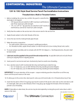
Placing the Starter in Service
1/2-13UNC-2B THREAD
.75” DEEP, 4 PLACES
Ø 1.5”
TYPE J518C FLANGE
Ø 102 FOR 3 1/2” PIPE (SLIP-ON TYPE FLANGE)
35.7
135
60° TYP.
R 64
3/8” N.P.T.
88
47.7
Ø 54.4
Ø 70.5
10.3
10.1
5.7
9.1
10.1
10.3
SLOT
DET. “A”
DET. “A”
45.7
10.41
10.16
13
117
69.80
34.90
178
424
59
53.3
51.5
233
180.2
159
54.5
54.2
Ø
177.86
177.80
Ø
50.8
49.3
Ø
502
89
1/2”-13UNC-2B THREAD
30 DEEP, 4 HOLES
2” SAE J518C
SPLIT FLANGE, DRAIN
OIL DRAIN
Ø 12 (2 HOLES
)
THRU
Ø 12.0 (4 HOLES)
THRU A 89.0
LONG BOSS
21.4
102
77.8
38.9
42.9
99
78
408
205
152.4
76.2
39
68.8
137.2
195
205
H
H
H
H
H
H
(Dwg. TPA1470-1)

4 03540697_ed4
Placing Starter in Service
The Ingersoll Rand Starter is a precision piece of equipment
intended to give ecient, economical performance over a long
period of time, However, as with any product, performance, economy
and durability are determined for the most part by a few simple
common sense procedures that can be recommended only by the
manufacturer and adhered to only by the customer.
The recommendations outlined in this manual are based
on 30 years of experience in the air and gas starter eld.
Study these recommendations and follow them. They can
save you considerable time and expense.
Installation
General Information
1. Always make certain your starter is properly installed. A little
extra time and eort spent in doing a top quality job will
contribute considerably toward a reliable starting system that
does a superior job of starting your engine quickly under all
conditions.
2. We strongly recommend that on all turbine engine installations,
and on stationary engines subject to vibration, you use hoses of
the specied diameter instead of rigid pipe connections. Turbine
engine vibration will soon loosen rigid pipe connections, whereas
hoses will absorb the vibration, and connections will remain
tight.
3. In the actual mounting of a starter, it is best to have the hose
connections already made at the receiver, and to have the starter
end of the hose handy for attaching to the starter. Wherever
possible, attach the air hoses to the starter before mounting
the starter on the engine housing. The reason for following this
procedure is two fold:
After mounting the starter, it is often impossible to make hose
connections due to space limitations.
Once the hoses are attached, they carry some of the weight of
the starter and make it easier to complete the mounting.
4. A strainer must be installed in the inlet line for each starter.
These 150 mesh strainers provide 100 micron ltration and oer
signicant protection against supply components.
Ingersoll Rand oers 3 sizes: ST900-267-24 for 1 inch lines,
ST900-267-32 for 2 inch lines and ST900-267-64 for 4 inch lines.
Replacement elements are: ST900-266-24 for 1 inch,
ST900-266-32 for 2 inch, and ST900-266-64 for 4 inch lines.
5. When installing the starter, you will usually need a regular ratchet
wrench, sockets, socket extension, Allen wrenches, and a torque
wrench.
6. The eciency of a starter can be greatly impaired by an improper
hook-up. Hoses smaller than those recommended will reduce the
volume of air to the motor, and the use of reducers in the exhaust
port will restrict the exhaust and choke the motor. The number of
tees and elbows, and the length of the supply line should be kept
to a minimum. Use 2” hose or pipe for supply lines up to 15 feet
long; use 2 1/2” hose or pipe if the supply line is over 15 feet long.
STRAINER
ST900-267-24
JIC 37° ADAPTER
1 1/2” NPT
1 1/2”
HOSE
1 1/2”
PIPE
1 1/2” PIPE
1/4” HOSE
1/4” HOSE
1/4” HOSE
3”
SRV150SS
RELAY VALVE
1 1/2”
HOSE
TS1400
STARTER
JIC 37° ADAPTER
1 1/2” NPT
SRV1500SS
RELAY VALVE
STRAINER
ST900-267-24
2” PIPE
SS825-1064
GAUGE
SMB-G618
CONTROL
VALVE
(Dwg.TPD1786)
a.
b.
7. A leak in any of the connections is hazardous. Make your
connections right the rst time to avoid unnecessary costs
and delays. On all threaded connections throughout the system,
use Loctite®* 56747 Sealant. Always run your air supply line
from the side or top of the receiver-never at or near the bottom.
Moisture in the air collects at the bottom of the receiver and
could cause corrosion in the starter motor or, worse yet, freeze
solid in cold weather so that the starter would be inoperative.
8. Whenever a ammable gas is being used to operate the Starter,
all discharges should be piped away to a safe area.
9. Whenever possible, always mount the starter so that the exhaust
port is downward. This will help prevent any accumulation of
water in the starter motor.
10. Maximum allowable pressures are:
Model Supply Pressure PSI/KPI Max.
TS1400 225/1551
190475-101 225/1551
TS1435 195/1343
190475-300 195/1343
TS1450 150/1034
TS1475 120/827
TS1499 90/620
Mounting the Starter
1. Study the piping diagram (Dwg. TPD1786).
2. Grease the O-ring with Parker O-ring lubricant and set in the
Gear Case.
3. Place the coupling (supplied by customer) on the
Drive Clutch Jaw.
4. Mount the Gear Case onto the engine.
5. Check for proper alignment of the lugs on the gear and driven
jaw with the coupling.
6. Tighten the mounting nuts to the recommended torque.
7. Insert one motor assembly into the Gear Case, meshing motor
pinion with Drive Gear. Check for proper orientation.
8. Alternately tighten the motor bolts to 55 ft.-lb. (74.5 Nm) torque.
9. Repeat Steps 8 and 9 for the other motor.
10. Using a 1 1/2” NPT Close Nipple, install the SRV15OSS Relay Valve
just after the strainer at each motor.
NOTICE
Make certain the connection is made to the outlet side of the
Relay Valve indicated by the word “OUT” cast on the valve body.
11. Install the No. SMB-G618 Starter Control Valve on an
appropriate panel.
12. Mount an SS825-1064 Pressure Gauge on, or adjacent to, the
control panel. It should be located where it is readily visible to the
operator of the control valve.
* Registered trademark of Loctite Corporation

03540697_ed4 5
13. Connect the Control Valve to the Relay Valve with 1/4“ hose.
Install a Tee in this line with a short feeder hose to the Pressure
Gauge.
NOTICE
Make certain the hose is connected to the “SUP” side of the
Control Valve.
14. Attach the required 1 1/2” hose, 2” pipe and lubricator/relay valve
assembly.
15. Install a 1/4“ hose line from the “DEL” side of the Starter Control
Valve to the top of the Relay Valve. Install a Tee in this line and a
short length of hose to the top of the other Relay Valve.
16. Install the required Exhaust System.
17. Pressurize the complete system and check every connection with
a soap bubble test. There must be no leaks.
Assembly Instructions
EXHAUST FLANGE
ST700-2574 MOTOR BOLT
(2) MOTOR ASSEMBLY
ST700-776 NUT
GEAR CASE ASSEMBLY
(Dwg. TPA1472)
This TS1400 starter is being shipped as three sub-assemblies to facilitate it’s assembly onto the turbine. To facilitate this nal assembly we oer
the following recommendations.
1. Remove the protective paper and tape from the gear case. Inspect nished surfaces to assure that they are clean and free of adhesive, nicks
and burrs.
2. The gear case should be ready for assembly onto the turbine. Visually check the inside of the gear case to conrm that there is no
contamination, and the gear coupling parts are free and secure.
3. After assembly of the gear case onto the turbine, remove the protective tape from the motor assembly.
4. Remove the shipping nut ST700-776 by holding it with a wrench and turning the motor bolts. Position the motor assembly to minimize
handling. Some of the parts will be loose after removing the nuts.
5. Inspect the nish surfaces to assure that they are clean and free of adhesive, nicks and burrs.
6. Inspect the O-rings to assure that they are free of adhesives, cuts, tears or abrasions.
7. Work O-ring lube into O-rings and grooves.
8. Without letting the parts move around, insert the motor assembly into the gear case, assure the correct rotational orientation of the inlet
and exhaust and alternately in steps, tighten the motor bolts to 55 ft. lbs.
9. Repeat steps 3 thru 8 with the other motor assembly.

6 03540697_ed4
Gear Assembly - Parts List
14
17A
13
15
17C
16
21
23
20
18
24
19
22
(Dwg. TPA1473-2)
ST999-A37 INT. GEAR CASE ASSEMBLY ST900-A108 PLANET GEAR FRAME ASSEMBLY
Item Part No. Name Qty. Item Part No. Name Qty.
17C SS800-22 Bearing 1 18 ST900-108 Frame 1
13 ST900-37 Gear Case 1 23 T06-24 Bearing 1
15 Y327-162 O-ring 1 20 ST900-24 Bearing 6
14 Y327-163 Seal 1 22 ST900-191 Pin 3
16 ST700-272 Seal 1 19 ST900-10 Gear 3
17A 04324596 Ring Gear 1 24 R3F-7 Screw 3
21 ST900-91 Spacer 3

03540697_ed4 7
Motor Assembly - Parts List
5
6
7
8
9
10
11
12
13
14
15
17
16
1
2
3
4
(Dwg. TPD1795)
Item Part No. Name Qty. Item Part No. Name Qty.
1 * Shaft 1 10 * Seal 2
2 * Nut 1 11 * Spacer 2
3 * Bearing 2 12 * Screw 2
4 * End Plate 1 13 * Pinion 1
5 * O-ring 2 14 * Nut 1
6 * Spacer 1 15 * Washer 1
7 * End Plate 1 16 * O-ring 2
8 * Rotor 1 17 * Spring 2
9 * Spacer 2
* These Parts Only Available as an Assembly.

8 03540697_ed4
Series TS1401 Turbine Starter - Sectional View
17
16
17C
35
34
29
28
30
33
31
32
27
26
25
35
13
23
17A
SEC. A-A
A
A
10
21
20
22
69
70
1
12B
6
7
2
12
12A
12B
19
8
18
14
24
15
(Dwg. TPA1469)

03540697_ed4 9
Series TS1401 Turbine Starter - Exploded View
30
29
28
26
25
35
33
32
31
34
35
25
15
13
14
17C
16
17
17A
23
22
20
21
19
20
8
9A
9
9
9
11
12A
12B
12B
12A
2
1
2A
36
37
12
7
6
5
4
3
10
18
24
27
(Dwg. TPA1468-1)

10 03540697_ed4
Series TS1401 Turbine Starter - Parts List
Item Part Description Part Number Item Part Description Part Number
Exhaust Kit ST700K-350 17A Carrier/Ring Gear 04324596
1 Directional Housing Exhaust Cover ST700-350 17C Bearing SS800-22
2 Exhaust Cover Seal Y330-257 18 Idler Gear Frame ST900-108
2A Exhaust Elbow Plug ROH-377 19 Idler Gear (3) ST900-10
3 Exhaust Adapter Seal Y327-46 20 Idler Gear Bearing (6) ST900-24
4 Exhaust Flange ST700-351 21 Idler Gear Bearing Spacer ST900-91
5 Weld Sleeve ST700-352 22 Idler Gear Shaft (3) ST900-191
6 Cap Screw (6) ST700-703 23 Gear Frame Bearing T06-24
7 Lock Washer (6) 845-55 24 Cap Screw (3) R3F-7
Motor Housing Assembly ST900-A40 25 Screw (2) WE205-817
8 Motor Housing ST900-40 26 Bearing Retaining Ring SS1600-265
9
Inlet Flange Kit
(Includes Inlet Flange, O-ring,
Mounting Bolts and Lock Washers)
ST700-K166
27 Bearing Spacer SS1600-366
28 Drive Gear Bearing (2) G7-24
29
Drive Gear SS1600K-9
10 Housing Plug (3) CE110-29 For B ratio models SS1600K-9B
11 Housing Plug Inlet Boss (2) ROH-377 For C ratio models SS1600K-9C
* Nameplate ST900-301 30 Shaft Retaining Rings SS1600-179
* Nameplate Screw (4) R4K-302 31 Drive Gear Shaft SS1600-8
12 Motor Assembly 32 Coupling SS1600-181
For 925 RH rotation models ST725R-A53A 33 Shoulder Screw SS1600-182
For 925 LH rotation models ST725L-A53A 34 Gear Case SS1600-37
For 935 LH rotation models ST735R-A53A
35
Rotor Pinion (2) SS1600K-17
For 935 RH rotation models ST735L-A53A For A ratio models SS1600K-17A
For 950 RH rotation models ST750R-A53A For B ratio models SS1600K-17B
For 950 LH rotation models ST750L-A53A For C ratio models SS1600K-17C
For 999 RH models ST799R-A53A For D ratio models SS1600K-17D
For 999 LH models ST799L-A53A 36 Starter Assembly Cap Screw (4) ST900-2574
12A Cylinder O-ring Seal (2) ST700-67 37 Cap Screw Washer (8) SS800-26
12B Housing O-ring Seal (2) Y327-32 * Tune Up Kit TS1401-TK1
Intermediate Gear Case Assembly ST999-A37
*
Rebuild Kit
13 Intermediate Gear Case ST900-37 For 25% ARC TS1401-RM1
14 Rear Gear Case O-ring Y327-163 For 35% ARC TS1401-RM3
15 Front Gear Case O-ring Y327-162 For 99% ARC TS1401-RM2
16 Seal ST700-272 For 50% ARC TS1401-RM4
17 Spacer ST900-90 * Gear Kit SS1600-APF-C-1329
* Not Illustrated

03540697_ed4 11
WARNING
Always wear eye protection when operating or performing any
maintenance on this starter. Always turn o the air or gas supply
and disconnect the air or gas supply hose before installing,
removing or adjusting any accessory on this starter or before
performing any maintenance on this starter.
Disassembly
General Information
1. Do not disassemble the starter any further than necessary to
replace worn or damaged parts.
2. When grasping a part in a vise, always use leather-covered or
copper-covered vice jaws to protect the surface of the part and
help prevent distortion. This is particularly true of threaded
members.
3. Do not remove any part which is a press t in or on a
subassembly unless the removal of that part is necessary for
replacement or repairs.
4. Always have a complete set of seals and O-rings on hand before
starting any overhaul of a Series TS1401 Turbine Starter. Never
reuse old seals or gaskets.
5. Always mark adjacent parts on the Housing Exhaust Cover (1) and
Motor Housing (8), so these members can be located in the same
relative position when the Starter is reassembled.
Disassembly of the Exhaust Elbow, Motor Assembly,
and Motor Housing and Intermediate Gear Case
1. If replacing the Motor Assembly (12) , remove both Housing
Plugs (10) and drain the oil from the gearing before beginning
disassembly of the Starter.
2. Using an 8 mm hex-head wrench, unscrew and remove the
Starter Assembly Cap Screws (36) and Washers (37).
3. Pull the Housing Exhaust Elbow (1) from the Motor Housing (8).
To dislodge the Housing Exhaust Elbow, rotate it until the Gears
clear the Motor Housing. Using a plastic hammer, tap the Gears
alternately until the Housing Exhaust Elbow can be removed from
the Motor Housing. Refer to Dwg. TPA1791.
(Dwg. TPA1791)
4. To disassemble the Housing Exhaust Elbow and components.
Refer to Dwg. TPA1784.
1
36
37
3
4
5
7
6
(Dwg. TPD1784)
5. Grasp the rear of the Motor Assembly (12) and pull it from the
rear of the Motor Housing. If the Motor Assembly is dicult
to remove, lightly push the motor pinion which is on the front
of the Motor Assembly towards the exhaust side of the Motor
Housing in order to free the Motor Assembly.
NOTICE
Do not attempt to separate the Motor Housing (8) from the
Intermediate Gear Case (13). This is a press t and requires
special bolts and air pressure to separate. This only should be
done at an authorized Ingersoll Rand repair facility.
6. Support the Intermediate Gear Case on a bench and position
it in a copper-faced vise so that the Intermediate Pinion (35) is
secured in the jaws of the vise. Tighten the vise only enough to
hold the Intermediate Pinion securely. Refer to Dwg. TPD1785
13
35
LOOSEN 1-1/2 TURNS
ONLY. DO NOT REMOVE
(Dwg. TPD1785)
7. Loosen the Intermediate Pinion Retaining Screw (25)
1 1/2 turns only. Do not remove.
WARNING
If the Intermediate Gear Case is not supported on a bench and if
the Intermediate Pinion Retaining Screw is completely removed,
the Intermediate Gear Case and components could fall causing
injury.
8. Remove the Intermediate Gear Case Assembly from the vise and
remove the Intermediate Pinion. Remove the Rear Gear Case
O-ring and Front Gear Case.
Maintenance

12 03540697_ed4
9. Remove the Carrier/Ring Gear (17A).
10. Remove Seal (16) and spacer (17).
11. Remove Bearing (17C) by pressing from front of Intermediate
Gear Case. Refer to Dwg. TPD1743.
17A
17C
14
13
15
17
16
(Dwg. TPD1743)
12. Remove the Cap Screws (24) from the Idler Gear Frame (18) and
remove the Idler Gear Frame from the front of the Motor Housing.
Refer to Dwg. TPD1745
PLANET GEAR
FRAME ASSEMBLY
24
8
(Dwg. TPD1745)
NOTICE
If the Idler Gear Frame will not come out of-the Motor Housing
easily, use a wooden dowel and tap the IdIer Gear Frame from
inside the rear of the Motor Housing.
13. If the Gear Frame Bearing (23) needs to be replaced, press it o of
the shaft of the Idler Gear Frame.
14. Press the Idler Gear Shafts (22) out of the Gear Frame and remove
the Idler Gears (19).
15. Press one of the Idler Gear Bearings (20) out of a Idler Gear,
remove the Spacer (21), and press out the other Idler Gear
Bearing. Repeat this process for the other two Idler Gears. Refer to
Dwg. TPD1741.
23
22
24
20
21
19
20
24
24
18
(Dwg. TPD1741)
Gear Case
1. With the Gear Case (34) facing up, the Drive Gear (29)
should be visible.
2. Remove the Retaining Ring (26) from the Shaft (31).
3. Using a gear puller, remove the Drive Gear.
4. Remove the Retaining Ring (26) from the Drive Gear.
5. Remove the Bearings (28) and Spacer (27).
6. Using a hex socket, remove the Shaft from the Gear Case.
NOTICE
These are left-hand threads.
TORQUE CHART
ILLUSTRATION NO. PART NO. ASSEMBLY TORQUE SEALANT REQUIRED
10 CE110-29 8 ft.-lb. (10.8 Nm) YES
6 ST700-2579 55 ft.-lb. (74.5 Nm) NO
24 R3 F-7 8 ft.-lb. (10.8 Nm) YES
33 SS1600-182 45 ft.-lb. (61 Nm) NO
25 WE205-817 90 ft.-lb. (122 Nm) Yes; under head
31 SS1600-8 150 ft.-lb. (203 Nm) NO
36 ST900-2574 55 ft.-lb. (74.5 Nm) NO
* IR SMB-441

03540697_ed4 13
Assembly
General Instructions
1. Always press on the inner ring of a ball-type bearing when
installing the bearing on a shaft.
2. Always press on the outer ring of a ball-type bearing when
pressing the bearing into a bearing recess.
3. Whenever grasping a starter or part in a vise, always use
leather-covered or copper-covered vise jaws. Take extra care with
threaded parts or housings.
4. Except for bearings, always clean every part and wipe every part
with a thin lm of oil before installation.
5. Check every bearing for roughness. If an open bearing must be
cleaned, wash it thoroughly in a clean, suitable, cleaning solution
and dry with a clean cloth. Sealed or shielded bearings should
never be cleaned. Work grease thoroughly into every open
bearing before installation.
6. Apply a lm of O-ring lubricant to all O-rings before nal
assembly.
Assembly of the Exhaust Elbow, Motor Assembly,
Motor Housing and Intermediate Gear Case
1. Press one Idler Gear Bearing (20) into a Idler Gear (19).
2. Press Idler Gear Spacer (21) into the Idler Gear until it seats
against the Bearing.
3. Press the other Idler Gear Bearing into the Idler Gear until it seats
against the Spacer. Repeat this procedure for the other two Idler
Gears.
4. Install the assembled Idler Gears in the Idler Gear Frame (18) by
aligning the holes in the Bearings with the holes in the Idler Gear
Frame and pressing in the Idler Gear Shafts.
5. Press the Gear Frame Bearing (23) on the shaft of the Idler Gear
Frame. Refer to Dwg. TPD1741.
23
22
24
20
21
19
20
24
24
18
(Dwg. TPD1741)
6. Install the Idler Gear Frame Assembly in the front of the Motor
Housing and secure it with Cap Screws (24). Torque to 8 ft.-lb.
(10.8 Nm) use Loctite Sealant. Refer to Dwg. TPD1745.
PLANET GEAR
FRAME ASSEMBLY
24
8
(Dwg. TPD1745)
7. Install the Spacer (17) on the shaft on the Carrier/Ring Gear (17A).
8. Using a bearing pressing tool of the proper size, press the Bearing
(17C) into the rear of the Intermediate Gear Case (13).
9. Using a sleeve which contacts the outer ring of the Seal (16),
press the Seal over the Spacer, at side rst.
NOTICE
Make sure that the at side of the seal will be installed against
the Bearing.
17A
17C
14
13
15
17
16
(Dwg. TPD1743)
10. Install the shaft of the Carrier through the Spacer until the
shoulder of the Carrier seats against the Spacer. Refer to
Dwg. TPD1743
11. For nal tightening, position the Intermediate Gear Case
so that the Intermediate Pinion is secured in the jaws of a
leather-covered or copper-faced vise. Tighten the Intermediate
Pinion Retaining Screw to 90 ft.-lb. (122Nm) torque.
Refer to Dwg. TPD1785

14 03540697_ed4
13
35
LOOSEN 1-1/2 TURNS
ONLY. DO NOT REMOVE
(Dwg. TPD1785)
12. Remove the Intermediate Gear Case from the vise and set it on a
bench.
13. Install the Rear Gear Case O-ring (14) in the groove at the rear of
the Intermediate Gear Case and the Front Gear Case O-ring (15) in
the groove at the front of the Intermediate Gear Case. Coat both
O-rings with O-ring lubricant.
14. Before installing the Motor Assembly, coat the O-rings on the
Motor Assembly and the inside of the Cylinder with O-ring
lubricant. Install the Motor Assembly through the rear of the
Motor Housing with the geared end of the rotor toward the front.
Refer to Dwg. TPD1161.
12A
12B
12A
12B
12
(Dwg. TPD1161)
NOTICE
Turn the Rotor Pinion so that the gear on the rotor meshes with
the Idler Planet Gears. Make sure that the rear of the Motor
Assembly is installed ush with the rear of the Cylinder. Motor
should be replaced every 1000 starts.
15. Align the punch marks on the Motor Housing with the punch
marks on the Intermediate Gear Case and using a plastic
hammer, tap the Motor Housing until it seats on the rear of the
Intermediate Gear Case. Refer to Dwg. TPD1792.
13
8
(Dwg. TPD1792)
Assembly of the Directional Housing Exhaust Cover
1. Coat the Exhaust Cover Seal (2) with O-ring lubricant and install in
the groove in the Directional Housing Exhaust Cover (1).
2. Install Directional Housing Exhaust Cover on the rear of the Motor
Housing in the desired orientation and using a plastic hammer,
tap the Directional Housing Exhaust Cover until it seats.
3. Secure the Directional Housing Exhaust cover on the rear of the
Motor Housing using the Starter Assembly Cap Screws (36) and
Cap Screw Washers (37). Using an 8 mm hex head wrench, tighten
each Cap Screw a little at a time to a nal torque of 55 ft.-lb. (74.5
Nm) in 20 ft.-lb. (27 Nm) increments.
Refer to Dwg . TPD1791.
4. Lubricate Exhaust Adapter Seal (3) with O-ring lubricant and
install in groove in Exhaust Flange (4).
5. Install Exhaust Flange with Exhaust Adapter Seal down on
Directional Housing Exhaust Cover. Align holes and secure
Adapter with Cap Screws (6) and Lock Washers (7). Tighten each
Cap Screw a little at a time to a nal torque of 55 ft.-lb. (74.5 Nm
torque) in 20 ft.-lb. (27 Nm) increments. Refer to Dwg. TPDl784.
NOTICE
Use Loctite® 56747 **Pipe Sealant on all plugs.
6. Position the Starter vertical with the Exhaust Elbow Plug up (2A).
Pour 15 ml of C32 Grade Turbine Oil into hole. Replace the Plug.
7. Install the bottom Housing Plug (10) and the Housing Plug Inlet
Boss (11). Put the Starter on its side with the side plug hole
upward. Add 175 ml (approximately 1/3 (.36) pint) C32 Grade
Turbine Oil through the side plug hole in the Motor Housing (8).
NOTICE
This oil should be changed every 500 starts.
Gear Case
1. With the Gear Case (34) facing up (the large single bore), install
the Drive Gear Shaft (31). Tighten to 150 ft.-lb. (203 Nm) torque.
NOTICE
These are left-hand threads.
2. Insert one Drive Gear Bearing (28 ), Spacer (27) and the other
Drive Gear Bearing (28) into the Drive Gear (29).
3. Install the Retaining Ring (26).
4. Press the Drive Gear Assembly onto the Drive Gear Shaft and
install the Retaining Ring (30).
** Registered trademark of Loctite Corp.

03540697_ed4 15
Test and Inspection Procedure
Do not overll.
Install the side Housing Plug (10) with Loctite® 56747 sealant and
tighten all plugs to 5 to 10 ft.-lb. (6.8 to 13.6 Nm) torque.
1. Motor and Gearing Freeness: Turn the Drive Shaft Pinion (35).
The Drive Shaft Pinion should turn by hand.
2. Motor Action: Secure Starter in a vise and apply 90 psig
(6.2 bar/620 kPa) pressure using a 3/8” (9 mm) supply line to the
inlet of the motor. Starter should run smoothly.
3. Motor Seals: Plug the exhaust and slowly apply 20 psig
(1.38 bar/138 kPa) pressure to the inlet of the motor. Pressure
should hold within 5 psi for 30 seconds.
4. Gear Case Seals: Plug the exhaust and slowly apply 20 psig
(1.38 bar/138 kPa) pressure to the inlet of the motor. There should
be no leakage in the housing joints in the Gear Case area or in
the shaft seal in the Intermediate Gear System. If the Starter is
properly sealed. Pressure should hold within 5 psi for 30 seconds.
5. Conrm Motor Rotation: Remove Housing Plug (10). Use a 1/4”
hex drive to rotate the motor to verify proper motor adjustment.
Intermediate Gearing output should rotate same as the required
Starter rotation while observing from the pinion side. Replace
Housing Plug.
6. Orientation: Drive Housing must be assembled to customer
orientation or per engineering drawing. If orientation is not
specied by customer, standard orientation will be supplied.
Check dimension prints on TPA1470.
7. Conrm Drive Rotation: Apply low pressure to motor and
observe rotation. Drive Pinion (35) must rotate in the direction
stamped on the nameplate. Chamfer on pinion teeth should be
on trailing edge of gear tooth.
8. Concentricity and Squareness of Shaft to Housing “D” Ratio
Only: Assemble indicator on shaft. Indicate Pilot diameter. Check
squareness of face at mounting surface. Pilot diameter must be
concentric within .008 max. T.I.R. Mounting face must be square
with shaft within .004 T.I.R. max.
TROUBLE SHOOTING GUIDE
Trouble Probable Cause Solution
Motor will not run
No air supply Check for blockage or damage to air supply lines or tank.
Damaged Motor Assembly (12)
Inspect Motor Assembly and power train and repair power train or
replace Motor Assembly if necessary.
Foreign material in Motor and/or piping Remove Motor Assembly and piping and remove the blockage.
Blocked exhaust system Remove Housing Exhaust Cover (1) and check for blockage.
Defective Control or Relay Valve Replace Control Valve or Relay Valve.
Loss of Power
Low air pressure to Starter Check air supply.
Restricted air supply line Check for blockage or damage to air lines. Check Filters.
Relay Valve malfunctioning Clean or replace lines or Relay Valve. Lubricate Relay Valve
Exhaust ow restricted
Check for blockage or damaged piping. Clean or replace piping.
Check for dirt or foreign material and clean or remove. Check for ice
build-up. Melt ice and reduce moisture build-up to Starter
Damaged Motor Assembly Replace Motor Assembly.
Motor runs, but does
not rotate turbine
Damaged or broken drive train Disassemble drive train and replace worn or damaged parts.
Oil blowing out of
exhaust
Oil in air supply line Inspect air line and remove source of oil.
Retaining Screw (6) or pipe plug missing. Install Retaining Screw or Pipe Plug.
Worn or damaged rotor seals or static
O-rings
Replace static seals on outside of Motor or send Motor to
Ingersoll Rand to be rebuilt.
Oil leaking
Worn or damaged O-rings Replace O-rings.
Loose joints
Make sure that joints t properly and Starter Assembly Cap Screws
are tightened to 55 ft.-lb. (74.5 Nm) torque. Make sure all seals and
O-rings t and seal properly at their perimeters. If they do not
replace with new seals and O-rings.
Excessive high speed operation Operate according to recommendations.
High number of start cycles Replace worn components.
Loose or leaking Pipe Plugs (10)
Tighten or replace Pipe plugs using Ingersoll Rand
No. SMB-441 Pipe Sealant.
Air or gas leakage
Loose joints
Make sure that joints t properly and Starter Assembly Cap Screws
are tightened to 55 ft.-lb. (74.5 Mn) torque. Make sure all seals and
O-rings t and seal properly at their perimeters. If they do not
replace with new seals and O-rings.
Excessive high-speed operation Operate according to recommendations.
High number of start cycles Replace worn components.
Loose or leaking Pipe Plugs Tighten or replace Pipe Plugs.

16 03540697_ed4
TS1401 MAINTENANCE SCHEDULE
Starts Components Recommendation
500 C3 Turbine Oil Replace
500 All External Cap Screws Check Torque
500 Strainer Check Element
1000 C3 Turbine Oil Replace
1000 All External Cap Screws Check Torque
1000 Motor Assembly Replace
1000 All Bearings and Seals Replace
1000 Strainer Check Element
1500 C3 Turbine Oil Replace
1500 All External Cap Screws Check Torque
1500 Strainer Check Element
2000 C3 Turbine Oil Replace
2000 Motor Assembly Replace
2000 All Bearings and Seals Replace
2000 All External Cap Screws Check Torque
2000 Strainer Check Element
2500 C3 Turbine Oil Replace
2500 All External Cap Screws Check Torque
2500 Strainer Check Element
3000 C3 Turbine Oil Replace
3000 Motor Assembly Replace
3000 All Bearings and Seals Replace
3000 All External Cap Screws Check Torque
3000 Strainer Check Element
3500 C3 Turbine Oil Replace
3500 All External Cap Screws Check Torque
3500 Strainer Check Element

03540697_ed4 17
Parts and Maintenance
CAUTION
The use of other than genuine Ingersoll Rand replacement parts may result in safety hazards, decreased motor performance, and
increased maintenance, and may invalidate all warranties.
Ingersoll Rand is not responsible for customer modication of motors for applications on which Ingersoll Rand was not consulted.
Repairs should be made only by authorized trained personnel. Consult your nearest Ingersoll Rand Authorized Service center.
When the life of the Starter has expired, it is recommended that the Starter be disassembled, degreased and parts be separated by material so
that they can be recycled.
Manuals can be downloaded from www.irtools.com.
Refer all communications to the nearest Ingersoll Rand Oce or Distributor.

Notes:

Notes:

www.irtools.com
© 2007 Ingersoll Rand Company
/