SECO-LARM E-941SA-1K2PQ Owner's manual

Category
Wall & ceiling mounts accessories
Type
Owner's manual

This manual is also suitable for

SECO-LARM E-941SA-1K2PQ is an electromagnetic lock designed to provide enhanced security for doors. It features a robust construction and a 1200-lb holding force, making it a reliable choice for securing high-security areas. The built-in dual-colored status LED and bond sensor provide real-time information about the lock's status, ensuring that the door is securely closed and locked. It offers easy installation with adjustable mounting brackets and detachable faceplates, allowing for flexible positioning and integration into various door types.

SECO-LARM E-941SA-1K2PQ is an electromagnetic lock designed to provide enhanced security for doors. It features a robust construction and a 1200-lb holding force, making it a reliable choice for securing high-security areas. The built-in dual-colored status LED and bond sensor provide real-time information about the lock's status, ensuring that the door is securely closed and locked. It offers easy installation with adjustable mounting brackets and detachable faceplates, allowing for flexible positioning and integration into various door types.

With LED, Bond Sensor
E-941SA-600PQ 600-lb. (272kg)
E-941SA-1K2PQ 1200-lb. (545kg)
Manual
Weatherproof
E-941SA-300 300-lb. (136kg)*
*E
-
941SA
-
300
is not UL listed.
Electromagnetic Locks
SECO-LARM Electromagnetic Locks
2 SECO-LARM U.S.A., Inc.
Table of Contents:
Introduction:
Features:
The E
-
941SA series of
electromagnetic locks is the ideal way to secure a door against unauthorized entry.
When power is applied to the electromagnetic lock, it creates an extremely strong magnetic field. The
electromagnet is strongly attracted to the steel armature plate which is mounted on the secured door. Once the
electromagnet is deactivated, the secured door will function normally without any residual magnetism.
Anodized aluminum.
No residual magnetism.
MOV surge protection.
Adjustable mounting bracket.
Complete mounting hardware for typical installations.
"L" bracket and "Z" brackets available for easy mounting.*
12/24VDC selectable.*
Detachable faceplate.*
E-941SA-1K2PQ and E-941SA-600PQ also feature:
Built-in dual-colored status LED and bond sensor to show
locking status:
E-941SA-300 features:
Weatherproof for outdoor use.
Pre-installed 36" (91cm) hookup wire included.
Parts List:
1 x Mounting plate
1 x Electromagnet
1 x Armature plate
1 x Armature screw
2 x Steel washers
1 x Rubber washer
1 x Door spacer
1 x Sexnut bolt
2 x Guide pins
4 x Long self-tapping screws
2 x Short self-tapping screws
2 x Hex-head mounting screws
2 x Tamper caps
2 x Hex wrenches
Specifications:
300
-
lb
600
-
lb
1,200
-
lb
Operating voltage
12VDC
±
10%
12
or
24 VDC
±
10%
Current draw
12VDC
315mA@
500mA
24VDC
N/A
250mA
Coil resistance
3
8
Ω±10%
48
Ω±10%(see page 8)
Bond sensor relay
N/A
3A@12VDC
Dimensions
Magnet
6
3
/
4
"
x1
"
x1
1
/
4
"
(170x23x32 mm)
9
7
/
8
"
x1
1
/
16
"
x1
5
/
8
"
(250x26x40 mm)
10
1
/
2
"
x1
5
/
8
"
x2
5
/
8
"
(268x42x67 mm)
Armature plate
6
1
/
4
"
x
9
/
16
"
x1
5
/
8
"
(159x14x41 mm)
7
1
/
4
"
x
1
/
2
"
x
1
1
/
2
"
(185x12x38 mm)
7
1
/
4
"
x
5
/
8
"
x2
3
/
8
"
(185x16x61 mm)
Operating temperature
14°~131° F (
-
10°~55° C)
Weight
2
-
lb 13.5
-
oz (1.3kg)
4
-
lb
6
-
oz (2kg)
11
-
lb
(5kg)
UL Listed
No
Yes
Yes
Green
Door is closed and locked
Red
D
oor not
closed and/or locked
Off
Door in use / No power
Installation
Wiring Diagram
Maximum Wiring Dis
tance
Troubleshooting
Warranty
Introduction
Features
Parts List
Specifications
Overview
and
Installation Applications
2
2
2
2
3
4
-
6
7
7
8
8
*E-941SA-300 does not have this feature.
SECO-LARM Electromagnetic Locks
SECO-LARM U.S.A., Inc. 3
"L"-Bracket
and
"Z"-Bracket
Short self-
tapping screws
Electromagnet
Mounting plate
Sexnut bolt
Door spacer
Armature screw
Tamper caps
Overview:
Installation Applications:
Long self-
tapping screws
Armature plate
Guide pins
Rubber washer
Steel washers
Hex-head
mounting screws
NOTE
: When mounting the electro
magnet, it may be necessary to use a
"
Z
"
-
bracket, 1 or 2
"
L
"
-
brackets,
and/or plate spacers, depending on the location and the type of door and frame. Use the diagram below to
help decide whether or not an optional bracket will be necessary for installation.
See page 7 for a complete list of SECO-LARM accessories.
.
"L" Bracket
Typical
Installation
"U" Bracket
(Typically for glass doors)
Plate
Spacers
Armature-
Mounting Plate
SECO-LARM Electromagnetic Locks
4 SECO-LARM U.S.A., Inc.
3. Place the template against
the door and frame. Mark
where the holes are to be
drilled.
Door Frame
Door
Template
1. Read this installation manual thoroughly. A clear understanding of the product and this
manual will make installation much easier.
2. The electromagnetic lock is designed for indoor use ONLY.
3. The most suitable mounting location for the electromagnetic lock may require the use of
additional SECO-LARM accessories such as Z-brackets, L-
brackets, and/or spacer plates.
Please see the diagram on page 3 to decide if a particular application requires any mounting
accessories. See page 7 for a complete list of SECO-LARM accessories.
4. Do not run power wires and signal wires in the same conduit as this may cause interference.
5. Do not install a diode in parallel with the electromagnetic lock as this may cause a delay
when releasing the door as well as cause residual magnetism.
6. The best location to install the electromagnetic lock is on the inside of the door that is being
secured with the wiring concealed in the frame to prevent tampering with the unit.
1. Fold the mounting template along the dotted line to
form a 90-degree angle.
4. Drill two holes in the frame and
three holes in the door as shown
on the template.
5. Use a hammer to lightly tap the
guide pins into the guide pin
holes on the armature plate.
2. Close the door. Find a mounting location on the door
frame near the upper free-moving corner of the door,
or as close as possible to the upper corner of the
door frame opposite the hinges.
Installation:
Installation Notes:
Door Frame
Door
Door Frame
Ideal
Mounting
Location
SECO-LARM Electromagnetic Locks
SECO-LARM U.S.A., Inc. 5
7. Put a rubber washer between the two metal
washers,
and place them over the armature screw between
the armature plate and the door. This allows the
plate to pivot around the screw to compensate for
door misalignment.
9. Screw the two short self-tapping screws through the mounting plate’s slotted holes, but do not over-tighten them.
Keeping them loose will allow for adjustment of the plate left or right so that the mounting plate and the armature
plate form a 90-degree angle. See the diagram below.
8.
Tighten the armature screw enough so that the
armature plate can withstand a break-in attempt, but
loose enough so that the armature plate can pivot
slightly. Make sure the anti-
spin guide pins are in the
two guide pin holes.
Mounting Plate
Armature Plate
90°
The rubber washer will be
sandwiched between the
two metal washers.
Armature
screw
Guide pins
6. Depending on the type of door being protected, drill holes according to the diagrams below:
Hollow Metal Door
Solid Core Door
Reinforced Door
1/4
"
(
6.8mm
)
for M
8x1
.25 thread
Drill a 5/16" (8mm) dia. hole through the
armature-plate side of the door for the
armature screw. Then drill a 5/8" (16mm)
dia. hole for sexnut screw on the
opposite
side of the door.
Drill an 5/16" (8mm) dia. hole on the
door for the armature screw, and drill a
1/2" (12.7mm) dia. and 1" (25mm)
deep
hole for the sexnut screw.
Drill a 1/4"
(6.8mm)
dia. and 1"
(25mm)
deep hole, tap for
M8x1.25 thread.
Tip:
Use a thread-locking compound
on the armature screw to ensure
a long-lasting installation.
Metal
washers
5/8
"
(
16mm
)
5/16
"
(
8
m
m
)
1/2
"
(
12
.7mm
)
5/16
"
(
8mm
)
300-lb and 600-lb
mounting plate
300
-
lb mounting plate
SECO-LARM Electromagnetic Locks
6 SECO-LARM U.S.A., Inc.
14. Cut the wires so they are long enough to connect
with the terminal block. Set the voltage using the
selection jumpers based on your input voltage.
10
. Once the position of the mounting plate is correct,
use the four long self-
tapping screws to permanently
mount the mounting plate.
11. Drill the cable access hole. Run the power leads
through the cable access hole in the mounting plate
and through the hole in the door frame.
12.
Remove the cover from the front of the
electromagnet. Run the power leads through the
large cable access hole .
13. Push the electromagnet against the mounting plate
so the electromagnet ends are
flush with the ends of
the mounting plate. Use the Allen wrench to screw
the hex-head mounting screws through the bottom
of the electromagnet into the mounting bracket.
Long self
-
tapping screws
Position a jumper over
the two middle pins for
24VDC operation
Position two jumpers
on all four pins for
12
VDC operation
Voltage Selection Jumpers
NOTE: This should be the very last step, as once the
tamper caps are in place they are very difficult to remove.
NOTE: Failure to correctly set the input voltage may cause
damage to the lock.
NOTE: Connect switching devices like push-to-exit
switches between the power source and the positive
terminal on the lock. Connecting switching devices to the
negative terminal may cause a delay in unlocking.
15.
Connect the power wires according to the wiring
diagram on page 7. Test the unit. Then replace the
front cover and install the hex-head tamper caps.
Skip this step for E-941SA-300. Power leads are
pre
-
installed. Faceplate does not detach.
SECO-LARM Electromagnetic Locks
SECO-LARM U.S.A., Inc. 7
Wire Length 25ft.
50ft.
75ft.
100ft.
150ft.
200ft.
250ft.
300ft.
400ft.
500ft.
1000ft.
Wire Gauge @ 500mA
20 18 18 18 16 14 14 12 10 -- --
Wire Length 25ft.
50ft.
75ft.
100ft.
150ft.
200ft.
250ft.
300ft.
400ft.
500ft.
1000ft.
Wire Gauge @ 250mA
24 24 22 20 18 18 16 16 14 14 14
24VDC Minimum Wire Gauge:
Wiring Diagram:
Maximum Distance from Power Source to Electromagnetic Lock:
12VDC Minimum Wir
e
Gauge:
Control
Device*
For a complete chart, please visit www.seco
-
larm.com
Optional SECO-LARM Electromagnetic Lock Accessories:
600-lb.
Models
1200-lb.
Models
E-941S-600/ZQ
E-941S-1K2/ZQ
E-941S-600/LQ
E-941S-1K2/LQ
E-941S-600/PQ
E-941S-1K2/PQ
E-941S-1K2/UQ
E-941S-600/UQ
"L" Brackets Plate Spacers
"Z" Brackets
(includes 1 "L" Bracket)
Glass Door
"U" Brackets
E-941S-1K2/HQ
E-941S-600/HQ
Armature
Plate Holders
Description
*NOTE
: Connect switching devices like
push-to-exit switches between the
power source and the positive terminal
on the lock. Connecting switching
devices to the negative terminal may
cause a delay in unlocking.
Position a jumper over
the two middle pins for
24VDC operation
Position tw
o jumpers
on all four pins for
12
VDC
operation
Voltage Selection Jumpers
Power Supply
Does not include armature plate
The Bond Status Sensor checks
to make sure the door is closed,
and the electromagnet is locked.
Bond
Status
Sensor
:
Green Door is closed and locked
Red Door not closed and/or locked
Off
Door in use
/
No power
600PQ and 1K2P models ONLY
LED Indicators:
(600PQ and 1K2P
models ONLY)
Note: Brackets and spacers are not available for E-941SA-300.
Note: E-941SA-300 is pre-wired.
SECO-LARM Electromagnetic Locks
8 SECO-LARM U.S.A., Inc.
No relay output
Troubleshooting:
LIFETIME LIMITED WARRANTY This SECO-LARM product is warranted against defects in material and workmanship
while used in normal service for the lifetime of the product. SECO-LARM’s obligation is limited to the repair or replacement
of any defective part if the unit is returned, transportation prepaid, to SECO-LARM. Under no circumstances will
SECO-LARM be responsible for any costs or charges for removal, installation, or reinstallation. This Warranty is void if
damage is caused by or attributed to acts of God, physical or electrical misuse or abuse, neglect, repair, or alteration,
improper or abnormal usage, or faulty installation, or if for any other reason SECO-LARM determines that such equipment is
not operating properly as a result of causes other than defects in material and workmanship. The sole obligation of
SECO-LARM, and the purchaser’s exclusive remedy, shall be limited to repair or replacement only, at SECO-LARM’s
option. In no event shall SECO-LARM be liable for any special, collateral, incidental, or consequential personal or property
damages of any kind to the purchaser or anyone else. This lifetime limited warranty is for products sold and installed in the
United States and Canada. For all other countries the warranty is 1 (one) year.
NOTICE: The information and specifications printed in this manual are current at the time of publication. However, the
SECO-LARM policy is one of continual development and improvement. For this reason, SECO-LARM reserves the right
to change specifications without notice. SECO-LARM is also not responsible for misprints or typographical errors.
Copyright © 2020 SECO-LARM U.S.A., Inc. All rights reserved. This material may not be reproduced or copied, in
whole or in part, without the written permission of SECO-LARM.
SECO-LARM
®
U.S.A., Inc.
16842 Millikan Avenue, Irvine, CA 92606 Website: www.seco-larm.com
Tel: 800-662-0800 / 949-261-2999 Fax: 949-261-7326 E-mail: sales@seco-larm.com
MI_E
-
941
S
A
-
xxxx
_20
07
2
4
.docx
Door does not l
ock
Bond status LED does not Illuminate
Check to make sure the wires are securely tightened to the terminal block
.
Check that the power supply is connected and operating.
Use a meter to check the resistance of coils inside the lock. See below.
Make sure the rubber washer is installed and free from damage.
Door locks, but can easily be forced open
Make sure the electromagnet and armature plate are properly aligned.
Make sure the contact surfaces of the electromagnet and armature
plate are clean and free from rust.
Check the power leads with a meter, and make sure 12VDC or 24VDC is
present.
Use a meter to check the resistance of coils inside the lock. See below.
Make sure the rubber washer is installed and free from damage.
The electromagnet is fitted with a metal oxide varistor to prevent
interference, so do not install a second diode.
Delay in door releasing
Check that the power is connected properly and turned on.
Make sure the lock is aligned properly.
Make sure the NO/NC/COM are wired properly.
PITGW1
1.
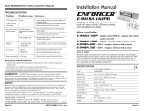
Remove the faceplate from the lock.
2. Disconnect the wire harness from the circuit board.
3. Using a meter, measure the resistance across:
Red / Green wires, and the Black / White wires.
4. Each coil should test 48Ω±10%.
5. If one or both of coils shows an open, short, or incorrect
resistance, replace the electromagnet.
White
Black
Green
Red
Wire Harness
:
48 ±10%
48 ±10%
If the Electromagnet has low or no holding force, check the resistance of the coils by
performing the following steps:
  • Page 1 1
  • Page 2 2
  • Page 3 3
  • Page 4 4
  • Page 5 5
  • Page 6 6
  • Page 7 7
  • Page 8 8

SECO-LARM E-941SA-1K2PQ Owner's manual

Category
Wall & ceiling mounts accessories
Type
Owner's manual
This manual is also suitable for

SECO-LARM E-941SA-1K2PQ is an electromagnetic lock designed to provide enhanced security for doors. It features a robust construction and a 1200-lb holding force, making it a reliable choice for securing high-security areas. The built-in dual-colored status LED and bond sensor provide real-time information about the lock's status, ensuring that the door is securely closed and locked. It offers easy installation with adjustable mounting brackets and detachable faceplates, allowing for flexible positioning and integration into various door types.

Ask a question and I''ll find the answer in the document

Finding information in a document is now easier with AI