Serial Communication Interface Conversion Solution
Transio A52/53 User’s Manual P/N: 1802000520516 Seventh Edition.
www.moxa.com ©2008 Moxa Inc.
Moxa Inc.
All rights reserved.
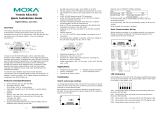
A52/A53 DTE Device
RJ45 DB9 Male
TxD 5 2 RxD
RxD 6 3 TxD
GND 7 5 GND
A52/A53 DCE Device
RJ45 DB25 Female
TxD 5 2 RxD
RxD 6 3 TxD
GND 7 7 GND
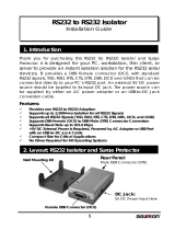
RS-422/RS-485 Pinouts
The RS-422/RS-485 port with RJ45 connector
or Terminal Block Connector is depicted as
follows.
~RS-422
A52/A53
RJ45 Jack
Connector Pinouts Signals
1 TxD -(A)
2 RTS -(A)
3 RTS +(B)
4/7 SG
5 TxD +(B)
6 RxD +(B)
8 CTS +(B)
9 CTS -(A)
10 RxD -(A)
A52/A53
Terminal Block
Connector Pinouts Signals
1 TxD +(B)
2 TxD -(A)
3 RxD +(B)
4 RxD -(A)
5 SG
6 Power GND
7 VCCA (9V)
Note: Pins 6 and 7 of the Terminal Block are for
Power GND and Power Input, which is an
alternate option for power adapter. Be
careful TO NOT confuse RS-422/RS-485
GND with Power GND.
SG: Signal Ground
~RS
-485
A52/A53
RJ45 Jack
Connector Pinouts Signals
1 Data-(A)
4 SG
5 Data+(B)
7 SG
A52/A53
Terminal Block
Connector Pinouts Signals
1 Data+(B)
2 Data-(A)
5 SG
6 Power GND
7 VCCA 9V
Note : Pins 6 and 7 of the Terminal Block are for
Power GND and Power Input, which is an
alternate option for power adapter. Be
careful TO NOT confuse RS-422/RS-485
GND with Power GND.
SG: Signal Ground
Transio A52/53
Smart RS-232 to RS-422/485
Bi-directional Converter
Overview
Transio A52/53 is a smart RS-232 to RS-422/485
bi-directional converter, which allows one RS-232
port to be converted into an RS-422 or RS-485
port. With A52/53 you can control up to 32
devices, within 1.2 km, in a multidrop
environment.
Transio A52/53 is a Moxa Green Product. Moxa’s
Green Products satisfy the RoHS directive of the
European Parliament, and accordingly, do not
contain cadmium and cadmium compounds,
hexavalent chromium compounds, lead and lead
compounds, mercury and mercury compounds,
PBBs (polybrominated biphenyls), or PBDEs
(polybrominated diphenyl ethers).
To ease 2-wire RS-485 half-duplex control, fully
Automatic Data Direction Control (ADDC)
intelligence that requires no baud rate switch
settings is designed into each A52/53, simplifying
RS-485 software programming. Your applications
can easily manage data transmitting and receiving
via the half-duplex RS-485 port without using
additional code. Compared to other products that
require setting the clock speed manually with
switches, A52/53 lets you avoid many developing
and
maintenance hassles.
To meet the high reliability required by harsh
industrial environments, all RS-422/485 signals
provide TVS protection, and ESD up to 25 KV. In
addition, A53 provides 2 KV of optical isolation
protection for all signals at the RS-422/485 end.
Features and Specifications
• Serial interface: RS-232, RS-422/485
• Port types: RS-232: RJ45;
RS-422/485: RJ45 or Terminal Block
• High speed, baud rate up to 921.6 Kbps; no
switch setting needed
• Signals:
RS-232: TxD, RxD, RTS, CTS, DTR, DSR,
DCD, GND;
RS-422: TxD+(B)/-(A), RxD+(B)/-(A),
RTS+(B)/-(A), CTS+(B)/-(A), GND;
RS-485-Data+(B)/-(A), GND
• Supports fully Automatic Data Direction
Control (ADDC) with no baud rate switch
settings for RS-485
• RS-485 data control modes: auto (ADDC) or
by RTS
• RS-422 supports CTS, RTS signals for
hardware flow control
• LED indicators for power and 4 signal states
(TxD, RxD, RTS, CTS)
• All RS-422/485 signals provide TVS
protection. (ESD 8 KV, EFT 2KV)
• All RS-422/485 signals support up to 2 KV
(DC) of optical isolation protection (A53
only)
• Provides overloading protection when there
are 2 signals shorted together at the
RS-422/485 end
• Built-in 120 ohm termination resistors for
RS-422/RS-485 (selectable with jumper by
RS-485 mode)
• Supports up to 32 units connected in an
RS-485 multidrop network
• CE approval
• 9V 1.5A UL/ TÜV 110V/230V power
adapter can support up to 4 converters
• An external power adapter is required, with
input voltage for the converter ranging from
DC +9V to +30V.
• Operating temperature: 0 to 55°C
• Dimensions: 90 x 60 x 21 mm
• Mounting Kit: Plastic Plates and screws for
mounting A52/53 on the wall or any surface.
• Power consumption: A52: 157 mA max.
(+9V); A53: 285A max. (+9V)
Applications
• Multipoint data acquisition
• Factory automation
• Remote serial device control
• Building security automation
• Critical industrial control
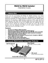
1 2 3 4 5 6 7
RJ45 Connector
Terminal Block Connector
1 2 3 4 5 6 7 8 9 10
RJ45 Plug Pin 1
RS-422/485 RS-232
Mounting
Screw
Fixing Screw
RJ45 Plu
Pin 1
RS-422/485
R45 ConnectorJ
Power Jack
RS-232
R45 ConnectorJ
External Power Connection
RS-422/485
Te r m i n a l Bl o c k