PC CHIPS M960G (V3.0A) User guide
- Category
- Motherboards
- Type
- User guide


i
Motherboard User’s Guide
This publication, including photographs, illustrations and software,
is under the protection of international copyright laws, with all
rights reserved. Neither this manual, nor any of the material
contained herein, may be reproduced without the express written
consent of the manufacturer.
The information in this document is subject to change without
notice. The manufacturer makes no representations or warranties
with respect to the contents hereof and specifically disclaims any
implied warranties of merchantability or fitness for any particular
purpose. Further, the manufacturer reserves the right to revise this
publication and to make changes from time to time in the content
hereof without obligation of the manufacturer to notify any person
of such revision or changes.
Trademarks
IBM, VGA, and PS/2 are registered trademarks of International
Business Machines.
Intel, Pentium/II/III, Pentium 4, Celeron and MMX are registered
trademarks of Intel Corporation.
Microsoft, MS-DOS and Windows 98/ME/NT/2000/XP are
registered trademarks of Microsoft Corporation.
AMI is a registered trademark of American Megatrends Inc.
SiS is a trademark of Silicon Integrated System Corporation.
Other names used in this publication may be trademarks and are
acknowledged.
Copyright © 2004
All Rights Reserved
M960G Series, V3.0B
S661FX/November 2004

ii
Motherboard User’s Guide
Table of Contents
Trademark ................................................................................... i
Static Electricity Precautions............................................................ iii
Pre-Installation Inspection ................................................................ iii
Chapter 1: Introduction............................................................ 1
Key Features ........................................................................................ 2
Package Contents ................................................................................5
Chapter 2: Motherboard Installation ..................................... 7
Motherboard Components................................................................... 8
I/O Ports .............................................................................................10
Installing the Processor ..................................................................... 11
Installing Memory Modules ...............................................................12
Jumper Settings ..................................................................................14
Install the Motherboard.....................................................................15
Connecting Optional Devices............................................................16
Install Other Devices..........................................................................19
Expansion Slots..................................................................................22
Chapter 3: BIOS Setup Utility............................................... 24
Introduction .......................................................................................24
Running the Setup Utility ........................... …………………………...25
Standard CMOS Setup Page .............................................................26
Advanced Setup Page ........................................................................27
Features Setup Page ..........................................................................29
Power Management Setup Page........................................................31
PCI/Plug and Play Setup Page..........................................................33
BIOS SecurityFeatures Setup Page ...................................................34
CPU PnP Setup Page .........................................................................35
Hardware Monitor Page....................................................................36
Load Optimal Settings .......................................................................37
Save Changes and Exit ......................................................................37
Discard Changes and Exit .................................................................37
Chapter 4: Software & Applications ..................................... 38
Introduction .......................................................................................38
Installing Support Software...............................................................39
Bundled Software Installation...........................................................41

iii
Motherboard User’s Guide
Static Electricity Precautions
Static electricity could damage components on this motherboard.
Take the following precautions while unpacking this motherboard
and installing it in a system.
1. Don’t take this motherboard and components out of their
original static-proof package until you are ready to install
them.
2. While installing, please wear a grounded wrist strap if
possible. If you don’t have a wrist strap, discharge static
electricity by touching the bare metal of the system chassis.
3. Carefully hold this motherboard by its edges. Do not touch
those components unless it is absolutely necessary. Put this
motherboard on the top of static-protection package with
component side facing up while installing.
Pre-Installation Inspection
1. Inspect this motherboard whether there are any damages to
components and connectors on the board.
2. If you suspect this motherboard has been damaged, do not
connect power to the system. Contact your motherboard
vendor about those damages.

iv
Motherboard User’s Guide
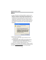
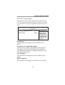
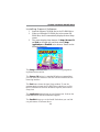
Notice:
1. Owing to Microsoft’s certifying schedule is various to every
supplier, we might have some drivers not certified yet by
Microsoft. Therefore, it might happen under Windows XP that
a dialogue box (shown as below) pop out warning you this
software has not passed Windows Logo testing to verify its
compatibility with Windows XP. Please rest assured that our
RD department has already tested and verified these drivers.
Just click the “Continue Anyway” button and go ahead the
installation.
2. USB 2.0 Driver Limitations:
2-1 The USB 2.0 driver only supports Windows XP and
Windows 2000.
2-2 If you connect a USB 2.0 hub to the root hub, plugging
USB devices into this hub, the system might not
successfully execute certain USB devices’ connection
because it could not recognize these devices.
Currently, we are working on such limitations’ solution. As soon
as the solution is done, the updated USB drive will be released to
our website:
www.pcchips.com.tw for your downloading.

1
Motherboard User’s Guide
Chapter 1 Introduction
This motherboard has a Socket-478 to support Intel Pentium 4
processors with Front-Side Bus (FSB) speeds up to 800 MHz.
It integrates the SiS661FX Northbridge and SiS964L Southbridge
that supports the built-in USB 2.0 providing higher bandwidth,
implementing Universal Serial Bus Specification Revision 2.0
and is compliant with UHCI 1.1 and EHCI 0.95. It supports
AC’ 97 Audio Codec and provides Ultra DMA 133/100/66
function. It has one 8x AGP, one CNR and five 32-bit PCI slots.
There is a full set of I/O ports including two PS/2 ports for mouse
and keyboard, one serial port, one parallel port, one LAN
port(optional), one VGA port, three audio jacks for Line-in, Line-
out and Microphone, four back-panel USB2.0 ports and onboard
USB headers USB2/USB3 providing extra ports by connecting
the Extended USB Module to the motherboard.
It is an ATX motherboard and has power connectors for an ATX
power supply.

2
Motherboard User’s Guide
Key Features
The key features of this motherboard include:
Socket-478 Processor
• Supports Intel Pentium 4 series CPU
• Supports up to 800 MHz Front-Side Bus
Chipset
There are SiS661FX Northbridge and SiS964L Southbridge in
this chipset in accordance with an innovative and scalable archi-
tecture with proven reliability and performance.
• Accelerated Graphics Port (AGP) Interface: Supports AGP
v2.0 Compliant and AGP 8x/4x/2x interface with Fast Write
Transaction
• Built-in a high performance 256-bit 3D engine and 32-bit
floating point format VLIW triangle setup engine
••
••
• Complete TV-OUT/Digital Flat Panel Solution: Built-in
secondary CRT controller to support independent display of
secondary CRT, LCD and TV-out
• Integrated Multi-threaded I/O link ensures concurrency of
upstream/down stream data transfer with 1 GB/s band-
width
• PCI 2.3 Specification Compliance
• Integrated Multithreaded I/O Link Mastering with Read
Pipelined Streaming
Memory Support
• Two 184-pin DIMM sockets for DDR SDRAM memory
modules
• Supports DDR400 memory bus
• Maximum installed memory is 2GB

3
Chapter 1: Introduction
Expansion Slots
• Five 32-bit PCI slots
• One 8x AGP slot
• One CNR slot
Onboard IDE channels
• Two IDE Connectors
• Supports PIO (Programmable Input/Output) and DMA
(Direct Memory Access) modes
• Supports IDE Ultra DMA bus mastering with transfer rates
of 133/100/66 MB/sec
Onboard VGA
• Built-in a high performance 256-bit 3D engine
• Supports AGP 2.0 compliant configuration setting
• Supports AGP 4X 266 MHz with 16 stages pipeline full
side-band/pipe function
AC’97 Audio Codec
• 6-CH hardware architecture allows multi-channel south
bridge to playback 6CH audio
• Intel
®
AC’97 (REV. 2.3) compatible, meeting Microsoft
®
PC2001 requirements
• Built-in earphone buffer and internal PLL, the latter saving
additional crystal
• Line-in/rear out share the same jack; Center/bass share the
MIC jack
• Digital S/PDIF OUT Support
• CRL
®
3D: HRTF based BS3D compatible audio engine
Onboard I/O Ports
The motherboard has a full set of I/O ports and connectors:
• Two PS/2 ports for mouse and keyboard
• One serial port
• One parallel port

4
Motherboard User’s Guide
• One VGA port
• One LAN port (optional)
• Four back-panel USB 2.0 ports
• Audio jacks for microphone, line-in and line-out
Fast Ethernet LAN (optional)
• Built-in 100Base-TX/10Base-T Physical Layer solution
• Dual Speed – 100/10 Mbps
• MII Interface to Ethernet Controller and Configuration &
Status
• Auto Negotiation: 10/100, Full/Half Duplex
• Meet All applicable IEEE 802.3, 10Base-T and 100 Base-
TX Standards
USB 2.0
• Compliant with Universal Serial Bus Specification Revision
2.0
• Compliant with Intel’s Enhanced Host Controller Interface
Specification Revision 0.95
• Compliant with Universal Host Controller Interface Specifi-
cation Revision 1.1
• PCI multi-function device consists of two UHCI Host
Controller cores for full-/low-speed signaling and one
EHCI Host Controller core for high-speed signaling
• Root hub consists 4 downstream facing ports with inte-
grated physical layer transceivers shared by UHCI and
EHCI Host Controller, up to eight functional ports
• Support PCI-Bus Power Management Interface Specifica-
tion release 1.1
• Legacy support for all downstream facing ports
BIOS Firmware
This motherboard uses AMI BIOS that enables users to configure
many system features including the following:
• Power management
• Wake-up alarms

5
Chapter 1: Introduction
• CPU parameters and memory timing
• CPU and memory timing
The firmware can also be used to set parameters for different
processor clock speeds.
Dimensions
• ATX form factor of 305 x 220 mm
Note: Hardware specifications and software items are
subject to change without notification.
Package Contents
Your motherboard package contains the following items:
The motherboard
The User’s Guide
One diskette drive ribbon cable (optional)
One IDE drive ribbon cable
The Software support CD
Optional Accessories
You can purchase the following optional accessories for this
motherboard.
The Extended USB module
The CNR v.90 56K Fax/Modem card
The Card Reader

6
Motherboard User’s Guide
Note: You can purchase your own optional accessories from
the third party, but please contact your local vendor on any
issues of the specification and compatibility.

7
Chapter 2: Motherboard Installation
Chapter 2 Motherboard Installation
To install this motherboard in a system, please follow these
instructions in this chapter:
• Identify the motherboard components
• Install a CPU
• Install one or more system memory modules
• Make sure all jumpers and switches are set correctly
• Install this motherboard in a system chassis (case)
• Connect any extension brackets or cables to headers/
connectors on the motherboard
• Install peripheral devices and make the appropriate connec-
tions to headers/connectors on the motherboard
Note:
1. Before installing this motherboard, make sure jumper JP2
is under Normal setting. See this chapter for information
about locating JP2 and the setting options.
2. Never connect power to the system during installation;
otherwise, it may damage the motherboard.

8
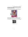
Motherboard User’s Guide
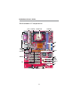
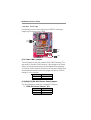
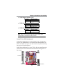
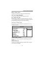
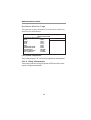
Motherboard Components
ATXPW1
IDE
DDR
SPK1
CNR1
PCI
IO PORTS
PANEL1
JP2
IR1
CPUFAN1
AGP1
SPDIFO1
READER1
SOCKET-478
USB2/3
JP5
FDD1
SYSFAN1
CPUPW1
SYSFAN2
AUDIO2
CD1
JP3/4
JP6

9
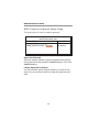
Chapter 2: Motherboard Installation
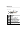
LABEL COMPONENTS
DDR1/2 Two 184-pin DDR SDRAM sockets
IDE1/2 Primary/Secondary IDE connectors
CPUPW1 Standard 4-Pin ATX Power connector
ATXPW1 Standard 20-Pin ATX Power connector
USB2/USB3 Front Panel USB headers
FDD1 Floppy Disk Drive connector
PANEL1 Front Panel Switch/LED header
SYSFAN1 System Fan connector
SYSFAN2 System Fan connector (optional)
JP2 Clear CMOS jumper
JP3 USBLAN1 Power Select jumper
JP4 USB1 Power Select jumper
JP5 USB2 Power Select jumper
JP6 USB3 Power Select jumper
SPK1 Speaker header
IR1 Infrared header
PCI 1-5 32-bit PCI slots
CD1 Analog Audio Input header
AUDIO2 Front Panel Audio header
READER1 USB Card Reader header
CPUFAN1 CPU Fan connector
CNR1 Communications Networking Riser slot

10
Motherboard User’s Guide
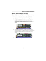
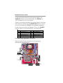
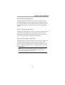
I/O Ports
The illustration below shows a side view of the built-in I/O ports
on the motherboard.
PS/2 Mouse Use the upper PS/2 port to connect a PS/2
pointing device.
PS/2
Keyboard
Use the lower PS/2 port to connect a PS/2
keyboard.
Parallel Port
(LPT1)
Use the Parallel port to connect printers or
other parallel communications devices.
COM1 Use the COM port to connect serial devices
such as mice or fax/modems. COM1 is
identified by the system as COM1.
VGA Use the VGA port to connect VGA devices.
LAN Port
(optional)
Connect an RJ-45 jack to the LAN port to
connect your computer to the Network.
USB Ports Use the USB ports to connect USB devices.
Note: The lower USB port located beside the
VGA port is shared with the READER1
header.
Audio Ports Use the three audio ports to connect audio
devices. The first jack is for stereo Line-In
signal. The second jack is for stereo Line-Out
signal. The third jack is for Microphone.
Optional
Shared with
READER1

11
Chapter 2: Motherboard Installation
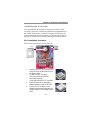
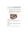
Installing the Processor
This motherboard has a Socket 478 processor socket. When
choosing a processor, consider the performance requirements of
the system. Performance is based on the processor design, the
clock speed and system bus frequency of the processor, and the
quantity of internal cache memory and external cache memory.
CPU Installation Procedure
Follow these instructions to install the CPU:
1 Install your CPU. Pull up the lever
away from the socket and lift up to
90-degree angle.
2 Locate the CPU cut edge
(the corner with the pin hold
noticeably missing).
Align and insert the CPU correctly.
3 Press the lever down and apply
thermal grease on top of the CPU.
4 Put the CPU Fan down on the
retention module and snap the four
retention legs of the cooling fan into
place.
CPUFAN1
Pin1
Socket 478
1

12
Motherboard User’s Guide
5 Flip the levers over to lock the heat
sink in place and connect the CPU
cooling Fan power cable to the
CPUFAN1 connector.
This completes the installation.
Installing Memory Modules
This motherboard accommodates two 184-pin 2.5V DIMM
sockets (Dual Inline Memory Module) for unbuffered DDR400/
333/266/200 (Double Data Rate SDRAM), and maximum 2.0 GB
installed memory.
DDR SDRAM is a type of SDRAM that supports data transfers
on both edges of each clock cycle (the rising and falling edges),
effectively doubling the memory chip’s data throughput. DDR
DIMMs can synchronously work with 400/333/266/200 MHz
memory and provide 3.2 GB/s, 2.7 GB/s, 2.1 GB/s and 1.6 GB/s
data transfer rate.
DDR1
DDR2

13
Chapter 2: Motherboard Installation
Memory Module Installation Procedure
These modules can be installed with up to 2 GB system memory.
Refer to the following to install the memory module.
1. Push down the latches on both sides of the DIMM
socket.
2. Align the memory module with the socket. There is a
notch on the DIMM socket that you can install the
DIMM module in the correct direction. Match the cutout
on the DIMM module with the notch on the DIMM
socket.
3. Install the DIMM module into the socket and press it
firmly down until it is seated correctly. The socket latches
are levered upwards and latch on to the edges of the
DIMM.
4. Install any remaining DIMM modules.

14
Motherboard User’s Guide
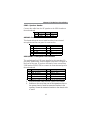
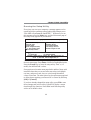
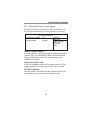
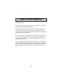
Jumper Settings
Connecting two pins with a jumper cap is SHORT; removing a
jumper cap from these pins, OPEN.
JP2: Clear CMOS Jumper
Use this jumper to clear the contents of the CMOS memory. You
may need to clear the CMOS memory if the settings in the Setup
Utility are incorrect and prevent your mainboard from operating.
To clear the CMOS memory, disconnect all the power cables from
the motherboard and then move the jumper cap into the CLEAR
setting for a few seconds.
JP3/JP4/JP5/JP6: USB Power Select Jumper
Use these jumpers to select the voltage for USB ports:
••
••
• USBLAN1 Power Selector: JP3
JP4
JP3
1
1
1
JP2
JP5
JP6
1
1
Function Jumper Setting
Clear CMOS Short Pins 1-2
Normal Short Pins 2-3
Function Jumper Setting
VCC5V Short pins 1-2
SB5V Short pins 2-3
Page is loading ...
Page is loading ...
Page is loading ...
Page is loading ...
Page is loading ...
Page is loading ...
Page is loading ...
Page is loading ...
Page is loading ...
Page is loading ...
Page is loading ...
Page is loading ...
Page is loading ...
Page is loading ...
Page is loading ...
Page is loading ...
Page is loading ...
Page is loading ...
Page is loading ...
Page is loading ...
Page is loading ...
Page is loading ...
Page is loading ...
Page is loading ...
Page is loading ...
Page is loading ...
Page is loading ...
-
 1
1
-
 2
2
-
 3
3
-
 4
4
-
 5
5
-
 6
6
-
 7
7
-
 8
8
-
 9
9
-
 10
10
-
 11
11
-
 12
12
-
 13
13
-
 14
14
-
 15
15
-
 16
16
-
 17
17
-
 18
18
-
 19
19
-
 20
20
-
 21
21
-
 22
22
-
 23
23
-
 24
24
-
 25
25
-
 26
26
-
 27
27
-
 28
28
-
 29
29
-
 30
30
-
 31
31
-
 32
32
-
 33
33
-
 34
34
-
 35
35
-
 36
36
-
 37
37
-
 38
38
-
 39
39
-
 40
40
-
 41
41
-
 42
42
-
 43
43
-
 44
44
-
 45
45
-
 46
46
-
 47
47


PC CHIPS M960G (V3.0A) User guide
- Category
- Motherboards
- Type
- User guide
Ask a question and I''ll find the answer in the document
Finding information in a document is now easier with AI
Related papers
-
PC CHIPS M810DG (V8.0a) User manual
-
-
-
Mercury M789CLU (V1.2) Specification
-
-
-
ECS P21G (V1.0) User manual
-
-
-