PC CHIPS P13G+ (V1.0) User guide
- Category
- Motherboards
- Type
- User guide

i
Motherboard User’s Guide
This publication, including photographs, illustrations and software, is under the
protection of international copyright laws, with all rights reserved. Neither this
user’s guide, nor any of the material contained herein, may be reproduced without
the express written consent of the manufacturer.
The information in this document is subject to change without notice. The manu-
facturer makes no representations or warranties with respect to the contents hereof
and specifically disclaims any implied warranties of merchantability or fitness for
any particular purpose. Further, the manufacturer reserves the right to revise this
publication and to make changes from time to time in the content hereof without
obligation of the manufacturer to notify any person of such revision or changes.
Trademarks
IBM, VGA, and PS/2 are registered trademarks of International Business Ma-
chines.
Intel, Pentium/II/III, Pentium 4, Celeron and MMX are registered trademarks of
Intel Corporation.
Microsoft, MS-DOS and Windows 98/ME/NT/2000/XP are registered trademarks
of Microsoft Corporation.
AMI is a trademark of American Megatrends Inc.
It has been acknowledged that other brands or product names in this manual are
trademarks or the properties of their respective owners.
Static Electricity Precautions
1. Don’t take this motherboard and components out of their original static-
proof package until you are ready to install them.
2. While installing, please wear a grounded wrist strap if possible. If you
don’t have a wrist strap, discharge static electricity by touching the bare
metal of the system chassis.
3. Carefully hold this motherboard by its edges. Do not touch those compo-
nents unless it is absolutely necessary. Put this motherboard on the top of
static-protection package with component side facing up while installing.
Pre-Installation Inspection
1. Inspect this motherboard whether there are any damages to components
and connectors on the board.
2. If you suspect this motherboard has been damaged, do not connect power
to the system. Contact your motherboard vendor about those damages.
Copyright © 2006
All Rights Reserved
P13G+ Series, V1.0
March 2006

ii
Motherboard User’s Guide
Table of Contents
Trademark ............................................................................................................ i
Static Electricity Precautions ......................................................................................... i
Pre-Installation Inspection ............................................................................................. i
Chapter 1: Introduction ..................................................................................... 1
Key Features .................................................................................................................... 1
Package Contents ........................................................................................................... 4
Chapter 2: Motherboard Installation .............................................................. 5
Motherboard Components ............................................................................................ 6
I/O Ports .......................................................................................................................... 8
Installing the Processor ................................................................................................. 9
Installing Memory Modules ........................................................................................ 1 0
Jumper Settings ............................................................................................................ 1 3
Install the Motherboard ............................................................................................... 1 4
Connecting Optional Devices ..................................................................................... 1 5
Install Other Devices ....................................................................................................1 8
Expansion Slots ............................................................................................................ 2 0
Dual Monitor..................................................................................................... 22
Chapter 3: BIOS Setup Utility ....................................................................... 23
About the Setup Utility....................................................................................... 2 3
Updating the BIOS............................................................................................ 24
Using BIOS....................................................................................................... 25
Standard CMOS Features.................................................................................. 2 6
Advanced BIOS Features ............................................................................................ 2 8
Advanced Chipset Features ......................................................................................... 3 2
Integrated Peripherals ................................................................................................. 3 4
Power Management Setup .......................................................................................... 3 9
PnP/PCI Configurations ..............................................................................................4 1
PC Health Status...................................................................................... .........42
Frequency Control ....................................................................................................... 4 4
Load Fail-Safe Defaults .............................................................................................. 4 5
Load Optimized Defaults ............................................................................................. 4 5
Set Supervisor Password .............................................................................................. 4 5
Set User Password............................................................................................. 45
Save & Exit Setup............................................................................................. 46
Exit Without Saving........................................................................................... 46
Chapter 4: Software & Applications .............................................................. 47
Introduction .................................................................................................................. 4 7
Installing Support Software ........................................................................................ 4 7
Bundled Software Installation .................................................................................... 4 9

iii
Motherboard User’s Guide
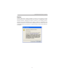
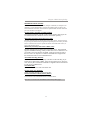
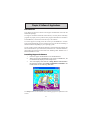
Notice:
Owing to Microsoft’s certifying schedule is various to every supplier, we might
have some drivers not certified yet by Microsoft. Therefore, it might happen under
Windows XP that a dialogue box (shown as below) pop out warning you this
software has not passed Windows Logo testing to verify its compatibility with
Windows XP. Please rest assured that our RD department has already tested and
verified these drivers. Just click the “Continue Anyway” button and go ahead the
installation.

1
Chapter 1: Introduction
Chapter 1 Introduction
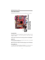
This motherboard has an LGA775 socket for latest Intel Pentium 4/Celeron D/
Pentium D processors with Hyper-Threading Technology and Front-Side Bus
(FSB) speeds up to 800/533/400 MHz. Hyper-Threading Technology, designed to
take advantage of the multitasking features in Windows XP, gives you the power to
do more things at once.
This motherboard integrates the Intel 865G Northbridge along with Intel I/O
Controller Hub 5 (ICH5) that supports the Serial ATA interface for high-perfor-
mance and mainstream desktop PCs; the built-in USB 2.0 providing higher band-
width, implementing Universal Serial Bus Specification Revision 2.0 and is
compliant with UHCI 1.1 and EHCI 1.0.
It supports 6-channel AC’97 Audio Codec and provides two IDE Ultra DMA 100/
66/33 channel. It has one AGP 8X slot, one CNR and two 32-bit PCI slots. There
is a full set of I/O ports including two PS/2 ports for mouse and keyboard, one VGA
port, one serial port, one parallel port, one LAN port (optional), three audio jacks
for micropone, line-in and line-out, and four back-panel USB 2.0 ports. In addition,
onboard USB headers provide extra ports by connecting the extended USB module
to the motherboard.
It is a Micro ATX motherboard and has power connectors for an ATX power
supply.
Key Features
The key features of this motherboard include:
LGA775 Socket Processor Support
• Supports the latest Intel Pentium 4/Celeron D/Pentium D Series pro-
cessors with Hyper-Threading Technology
• Supports up to 800/533/400 MHz Front-Side Bus
.
Chipset
There are Intel 865G Northbridge and Intel I/O Controller Hub 5 (ICH5) in the
chipsets in accordance with an innovative and scalable architecture with proven
reliability and performance.
• Host Interface Support
− One Intel
Pentium 4 processor with 512-KB L2 cache on 0.13 micron
process / Pentium 4 processor on 90 nm process
• Hyper-Threading Technology
Note: Hyper-Threading technology enables the operating system into thinking
it’s hooked up to two processors, allowing two threads to be run in parallel,
both on separate ‘logical’ processors within the same physical processor

2
Motherboard User’s Guide
• System Memory Controller Support
− Dual-channel (6.4 GB/s wide) DDR memory interface
− Single-channel (3.2 GB/s wide) operation supported
− Supports DDR266, DDR333, DDR400 DIMM modules
• PCI Bus Interface
− Supports PCI Revision 2.3 Specification at 33 MHz
• Integrated LAN Controller
− 10/100 Mbp/s Faster Ethernet Support
• Integrated Serial ATA Host Controllers
− Independent DMA operation on two ports
− Data transfer rates up to 1.5 Gb/s (150 MB/s)
• Integrated IDE Controller
− Ultra ATA100/66/33, BMIDE and PIO modes
• USB 2.0
− Includes 4 UHCI Host Controllers, increasing the number of external
ports to eight
• AC-Link for Audio and Telephony Codecs
− Support for 3 AC’97 2.3 codecs−533 MT/s (133 MHz) FSB and 800
MT/s (200 MHz) FSB
− Supports Hyper-Threading Technology (HT Technology)
− FSB Dynamic Bus Inversion (DBI)
Memory Support
• Two 184-pin DIMM sockets for DDR SDRAM DDR400/333/266 memory
modules
• Maximum installed memory is 2 GB
Expansion Slots
• One AGP 8X slot
• Two 32-bit PCI slots
• One CNR slot
Onboard IDE channels
• Two IDE Channels supporting ATA-33, ATA-66, ATA-100
• Supports PIO (Programmable Input/Output) and DMA (Direct Memory
Access) modes
• Supports IDE Ultra DMA bus mastering with transfer rates of 100/66/33
MB/s
Serial ATA
• Two Serial ATA Connectors
• Transfer rate exceeding best ATA (1.5 Gb/s) with scalability to higher rates
• Low pin count for both host and devices
AC’97 Audio Codec
• Compliant with AC’97 2.3 specification

3
Chapter 1: Introduction
• Front-Out, Surround-Out, MIC-In and LINE-In Jack Sensing
• Three analog line-level stereo inputs with 5-bit volume control: LINE_IN,
CD, AUX
• Two analog line-level mono input
• Standard 48-Pin LQFP
Onboard I/O Ports
• Two PS/2 ports for mouse and keyboard
• One serial port
• One parallel port
• One VGA port
• One LAN port (optional)
• Four back-panel USB2.0 ports
• Audio jacks for microphone, line-in and line-out
Fast Ethernet LAN (optional)
• 10 Mb/s and 100 Mb/s operation
• Integrated Fast Ethernet MAC, physical chip, and transceiver onto a single
chip
• Supports 10 Mb/s and 100 Mb/s N-way auto-negotiation
• Support ACPI power management
• Full Duplex Flow Control (IEEE 802.3x) and Half/Full duplex capability
USB 2.0
• Compliant with Universal Serial Bus Specification Revision 2.0
• Compliant with Intel’s Enhanced Host Controller Interface Specification
Revision 1.0
• Compliant with Universal Host Controller Interface Specification Revi-
sion 1.1
• PCI multi-function device consists of two UHCI Host Controller cores
for full-/low-speed signaling and one EHCI Host Controller core for high-
speed signaling
• Root hub consists 4 downstream facing ports with integrated physical
layer transceivers shared by UHCI and EHCI Host Controller, up to eight
functional ports
• Support PCI-Bus Power Management Interface Specification release 1.1
• Legacy support for all downstream facing ports
BIOS Firmware
This motherboard uses AWARD BIOS that enables users to configure many sys-
tem features including the following:
• Power management
• Wake-up alarms
• CPU parameters and memory timing
• CPU and memory timing

4
Motherboard User’s Guide
The firmware can also be used to set parameters for different processor clock
speeds.
Dimensions
• Micro ATX form factor of 244 x 220 mm
Note: Hardware specifications and software items are subject to change without
notification.
Package Contents
Your motherboard package ships with the following items:
The motherboard
The User’s Guide
One diskette drive ribbon cable (optional)
One IDE drive ribbon cable
The Software support CD
Optional Accessories
You can purchase the following optional accessories for this motherboard.
The Extended USB module
The CNR v.90 56K Fax/Modem card
The Serial ATA cable
The Serial ATA power cable
Note: You can purchase your own optional accessories from the third party, but
please contact your local vendor on any issues of the specification and
compatibility.

5
Chapter 2: Motherboard Installation
Chapter 2 Motherboard Installation
To install this motherboard in a system, please follow these instructions in this
chapter:
Identify the motherboard components
Install a CPU
Install one or more system memory modules
Make sure all jumpers and switches are set correctly
Install this motherboard in a system chassis (case)
Connect any extension brackets or cables to headers/connectors on the
motherboard
Install peripheral devices and make the appropriate connections to head-
ers/connectors on the motherboard
Note:
1 Before installing this motherboard, make sure jumper CLR_CMOS is
under Normal setting. See this chapter for information about locating
CLR_CMOS and the setting options.
2 Never connect power to the system during installation; otherwise, it may
damage the motherboard.

6
Motherboard User’s Guide
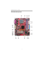
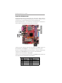
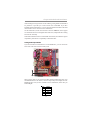
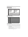
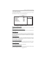
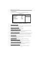
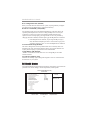
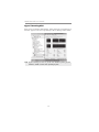
Motherboard Components

7
Chapter 2: Motherboard Installation
ITEM
LABEL
COMPONENTS
1 CPU Socket LGA775 Socket for Intel Pentium 4/Celeron
D/Pentium D CPUs
2 CPU_FAN CPU Fan connector(4PIN)
3 DIMM1/DIMM3 184-pin DDR SDRAM sockets (Support Dual-
Channel DDR400
)
4 IR1 Infrared header
5 FDD1 Floppy Disk Drive connector
6 ATX1 Standard 20-Pin ATX Power connector
7 IDE1 Primary IDE connector
8 IDE2 Secondary IDE connector
9 SPK1 Speaker header
10 CLR_CMOS Clear CMOS jumper
11 BIOS_WP BIOS protect jumper
12 SATA1~2 Serial ATA connectors
13 PANEL1 Front Panel Switch/LED header
14 USB3~4 Front Panel USB headers
15 CNR1 CNR slot
16 AUDIO1 Front Panel Audio header
17 AUX_IN Auxiliary In header
18 CD_IN Analog Audio Input header
19 SPDIFO1 SPDIF out header
20 PCI1~2 32-bit add-on card slots
21 AGP1 Accelerated Graphics Port slot
22 SYS_FAN System Fan connector
23 ATX12V 4-pin +12V power connector

8
Motherboard User’s Guide
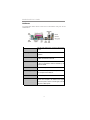
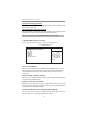
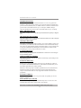
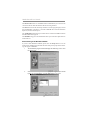
I/O Ports
The illustration below shows a side view of the built-in I/O ports on the
motherboard.
PS/2 Mouse
Use the upper PS/2 port to connect a PS/2 pointing
device.
PS/2 Keyboard
Use the low er PS/2 port to connect a PS/2
keyboard.
Parallel Port (LPT1)
Use the Parallel port to connect printers or other
parallel communications devices.
COM1
Use the COM port to connect serial devices such
as mic e or f ax /mod ems . COM1 is identif ied by the
s y s tem as COM1 .
VGA1
Use the VGA1 port to connect VGA devices.
LAN Port (optional)
Connect an RJ-45 jack to the LAN port to connect
your computer to the Netw ork.
USB Po r t s
Use the USB ports to connect USB devices.
Audio Ports
Use these three audio jacks to connect audio
devices. The f irst jack is for stereo Line-In signal,
the second jack for stereo Line-Out signal, and the
third jack for Microphone.
(optional)

9
Chapter 2: Motherboard Installation
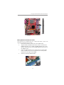
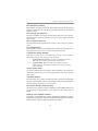
Installing the Processor
This motherboard has an LGA775 socket for the latest Intel Pentium 4/Celeron
D/Pentium D processors. When choosing a processor, consider the performance
requirements of the system. Performance is based on the processor design, the
clock speed and system bus frequency of the processor, and the quantity of inter-
nal cache memory and external cache memory.
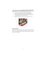
CPU Installation Procedure
Follow these instructions to install the CPU:
A. Unload the cap
• Use thumb & forefinger to hold the
lifting tab of the cap.
• Lift the cap up and remove the cap
completely from the socket.
B. Open the load plate
• Use thumb & forefinger to hold the
hook of the lever, pushing down and
pulling aside unlock it.
• Lift up the lever.
• Use thumb to open the load plate.
Be careful not to touch the contacts.
1
CPUFAN
LGA775 Socket
pin1

10
Motherboard User’s Guide
C. Install the CPU on the socket
• Orientate CPU package to the socket.
Make sure you match triangle marker
to pin 1 location.
D. Close the load plate
• Slightly push down the load plate onto
the tongue side, and hook the lever.
• CPU is locked completely.
E. Apply thermal grease on top of the CPU.
F. Fasten the cooling fan supporting base
onto the CPU socket on the
motherboard.
G. Make sure the CPU fan is plugged to
the CPU fan connector. Please refer to
the CPU cooling fan user’s manual for
more detail installation procedure.
Installing Memory Modules
This motherboard accommodates two 184-pin DIMM sockets (Dual Inline Memory
Module) for unbuffered DDR400/333/266 memory modules (Double Data Rate
SDRAM), and maximum 2.0 GB installed memory. DDR SDRAM is a type of
SDRAM that supports data transfers on both edges of each clock cycle (the rising
and falling edges), effectively doubling the memory chip’s data throughput.
This motherboard provides the Dual Channel Technology; when activating it, the
bandwidth of memory bus will be doubled to 6.4 GB/s and Frequency 200 MHz.
Note1:To achieve better airflow rates and heat dissipation, we suggest that you
use a high quality fan with 3800 rpm at least. CPU fan and heatsink
installation procedures may vary with the type of CPU fan/heatsink
supplied. The form and size of fan/heatsink may also vary.
Note2:The fan connector supports the CPU cooling fan of1.1A~2.2A (26.4W
max.) at +12V.

11
Chapter 2: Motherboard Installation
Memory Module Installation Procedure
These modules can be installed with up to 2 GB system memory. Refer to the
following to install the memory module.
1. Push down the latches on both sides of the DIMM socket.
2. Align the memory module with the socket. There is a notch on the
DIMM socket that you can install the DIMM module in the correct
direction. Match the cutout on the DIMM module with the notch on
the DIMM socket.
3. Install the DIMM module into the socket and press it firmly down
until it is seated correctly. The socket latches are levered upwards
and latch on to the edges of the DIMM.
4. Install any remaining DIMM modules.
DIMM1/3

12
Motherboard User’s Guide
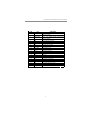
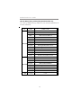
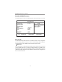
Table A: DDR (memory module) QVL (Qualified Vendor List)
The following DDR400 memory module have been tested and qualified for use
with this motherboard.
Size Vendor Module Name
Apacer AM3A568ACT05A
Corsair Platinum CMX256-3200C2PT
GEIL G208L364D1TG5NKT3C
GEIL GE08L3264D1WL5NKT3H71
GEIL GL3L32G88TG-5A
Kingston D3208DL2T-5 0323PT01
Kingston Winbond W942508BH-5
Kingston Samsung K4H560838D-TCC4
Ramaxel Samsung K4H560838D-TCC4
Ramaxel MIC-R 46V32M8TG-5BC
Samsung K4H560838E-TCCC
Samsung K4H560838D-TCCC
256 MB
Soutec M2G9108AKAS09F083S9DT
COSAIR Platinum CMX512-3200C2PT
GEIL GE16L6464D2WL5NKT3H66
Hynix HY5DU56822BT-D43
Kingston Winbond W942508BH-5
Kingston Samsung K4H560838D-TCC4
Kingmax KDL388P4EA-50
Samsung K4H560838E-TCCC
512 MB
TwinMOS M2G9J16AKATT9F083S9DT
1 GB
A-DATA Vitesta

13
Chapter 2: Motherboard Installation
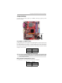
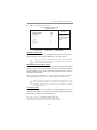
Jumper Settings
Connecting two pins with a jumper cap is SHORT; removing a jumper cap from
these pins, OPEN.
CLR_CMOS: Clear CMOS Jumper
Use this jumper to clear the contents of the CMOS memory. You may need to clear
the CMOS memory if the settings in the Setup Utility are incorrect and prevent
your motherboard from operating. To clear the CMOS memory, disconnect all the
power cables from the motherboard and then move the jumper cap into the CLEAR
setting for a few seconds.
Note: To avoid the system unstability after clearing CMOS, we recommend users
to enter the main BIOS setting page to “Load Optimal De-faults” and then
“Save Changes and Exit”.
Function Jumper
Normal Short Pins 1-2
Clear CMOS Short Pins 2-3
BIOS_WP: BIOS FLASH PROTECT Jumper
Use this jumper to set the BIOS FLASH PROTECT function.
Function Jumper
DISA BL E OPEN
ENA BLE SHORT
1
CLR_CMOS
1
BIOS_WP

14
Motherboard User’s Guide
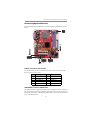
Connect the power connector from the power supply to the ATX1 connector on
the motherboard. The ATX12V is a +12V connector for CPU Vcore power.
If there is a cooling fan installed in the system chassis, connect the cable from the
cooling fan to the SYS_FAN fan power connector on the motherboard.
Connect the CPU fan connector to CPU_FAN.
Connect the case switches and indicator LEDs to the PANEL1 header. Please refer
to the following list of the PANEL1 pin assignments.
Install the Motherboard
Install the motherboard in a system chassis (case). The board is a Micro ATX size
motherboard. You can install this motherboard in an ATX case. Make sure your
case has an I/O cover plate matching the ports on this motherboard.
Install the motherboard in a case. Follow the case manufacturer’s instructions to
use the hardware and internal mounting points on the chassis.
Pin Signal Pin Signal
1 HD_LED_P( +) 2 FP PWR/SLP( +)
3 HD_LED_N( - ) 4 FP PWR/SLP( - )
5 RESET_SW_ N( - ) 6 POWER_SW_ P( +)
7 RESET_SW_ P( +) 8 POWER_ SW _ N( - )
9 RSV D_DNU 10 KEY
ATX1
ATX12V
1
PANEL1
SYS_FAN
1

15
Chapter 2: Motherboard Installation
Connecting Optional Devices
Refer to the following for information on connecting the motherboard’s optional
devices:
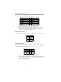
AUDIO1: Front Panel Audio Header
This header allows the user to install auxiliary front-oriented microphone and
line-out ports for easier access.
Pin Signal Pin Signal
1 A UD_MIC 2 A UD_GND
3 AUD_MIC_BIAS 4 AUD_VCC
5 A UD_FPOUT_R 6 A UD_RET_R
7 HP_ON 8 KEY
9 A UD_FPOUT_L 10 A UD_RET_L
USB3/USB4: Front Panel USB Headers
The motherboard has USB ports installed on the rear edge I/O port array. Addition-
ally, some computer cases have USB ports at the front of the case. If you have this
kind of case, use auxiliary USB headers USB3/USB4 to connect the front-mounted
ports to the motherboard.
1
IR1
AUDIO1
1
USB3
1
USB4
1
SPK1
1
1
AUX_IN
SPDIFO1
1

16
Motherboard User’s Guide
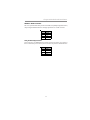
1 Locate the USB3/USB4 header on the motherboard.
2 Plug the bracket cable onto the USB3/USB4 header.
3 Remove a slot cover from one of the expansion slots on the system
chassis. Install an extension bracket in the opening. Secure the
extension bracket to the chassis with a screw.
Pin Signal Pin Signal
1 USB DUA L V CC 2 USB DUA L V CC
3 USBP4- 4 USBP5-
5 USBP4+ 6 USBP5+
7 GROUND 8 GROUND
9 KEY 10 USBOC45#
IR1: Infrared Header
The infrared port allows the wireless exchange of information between your com-
puter and similarly equipped devices such as printers, laptops, Personal Digital
Assistants (PDAs), and other computers.
Here is a list of headers USB3/USB4 pin assignments.
1 Locate the infrared port-IR1 header on the motherboard.
2 If you are adding an infrared port, connect the ribbon cable from the
port to the IR1 header and then secure the port to an appropriate
place in your system chassis.
Pin Signal Pin Signal
1NC2KEY
3+5V 4GND
5 IRTX 6 IRRX
SPK1: Speaker Header
Connect the cable from the PC speaker to the SPK1 header on the motherboard.
Pin Signal
1Sigal
2Key
3GND
4VCC

17
Chapter 2: Motherboard Installation
SPDIFO1: SPDIF out header
This is an optional header that provides an S/PDIF (Sony/Philips Digital Interface)
output to digital multimedia device through optical fiber or coaxial connector.
Pin Signal
1SPDIF
2+5VA
3Key
4GND
AUX_IN: Auxiliary In header
Pin Signal
1AUX_L
2GND
3GND
4AUX_R
This connector is an additional line-in audio connector. It allows you to attach a
line-in cable when your rear line-in jack is set as line out port for 4-channel function.
Page is loading ...
Page is loading ...
Page is loading ...
Page is loading ...
Page is loading ...
Page is loading ...
Page is loading ...
Page is loading ...
Page is loading ...
Page is loading ...
Page is loading ...
Page is loading ...
Page is loading ...
Page is loading ...
Page is loading ...
Page is loading ...
Page is loading ...
Page is loading ...
Page is loading ...
Page is loading ...
Page is loading ...
Page is loading ...
Page is loading ...
Page is loading ...
Page is loading ...
Page is loading ...
Page is loading ...
Page is loading ...
Page is loading ...
Page is loading ...
Page is loading ...
Page is loading ...
Page is loading ...
-
 1
1
-
 2
2
-
 3
3
-
 4
4
-
 5
5
-
 6
6
-
 7
7
-
 8
8
-
 9
9
-
 10
10
-
 11
11
-
 12
12
-
 13
13
-
 14
14
-
 15
15
-
 16
16
-
 17
17
-
 18
18
-
 19
19
-
 20
20
-
 21
21
-
 22
22
-
 23
23
-
 24
24
-
 25
25
-
 26
26
-
 27
27
-
 28
28
-
 29
29
-
 30
30
-
 31
31
-
 32
32
-
 33
33
-
 34
34
-
 35
35
-
 36
36
-
 37
37
-
 38
38
-
 39
39
-
 40
40
-
 41
41
-
 42
42
-
 43
43
-
 44
44
-
 45
45
-
 46
46
-
 47
47
-
 48
48
-
 49
49
-
 50
50
-
 51
51
-
 52
52
-
 53
53


PC CHIPS P13G+ (V1.0) User guide
- Category
- Motherboards
- Type
- User guide
Ask a question and I''ll find the answer in the document
Finding information in a document is now easier with AI
Related papers
-
PC CHIPS P53G (V1.0) User manual
-
PC CHIPS P65G Datasheet
-
-
ECS P21G (V1.0) User manual
-
-
ECS M985G Series User manual
-
-
-
Mercury M789CLU (V1.2) Specification
-
