6
Regency
®
P36D-1 Zero Clearance Direct Vent Gas Fireplace
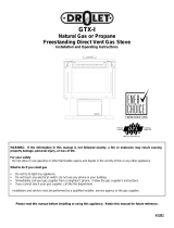
SAFETY LABEL
This is a copy of the label that accompanies each P36D-1 Zero Clearance Direct Vent Gas Fireplace. We have printed a copy of the contents here for your
review. The safety label is located on the front inside base of the unit, visible when the bottom louver is open.
NOTE: FPI units are constantly being improved. Check the label on the unit and if there is a difference, the label on the unit is the correct one.
COPY OF SAFETY DECAL FOR P36D-1
DO NOT REMOVE THIS LABEL / NE PAS ENLEVER CETTE ÉTIQUETTE
306
306
DOOR SEAL: Please
check that the door is
properly sealed
Minimum Clearances to Combustibles /
Degagement Minimum De Materiaux Combustibles
Serial No./ No de serie
918-500a
The "Bay Louvers" be
used with the Bay Glass option
MUST
MAY BE INSTALLED IN MANUFACTURED (MOBILE) HOMES AFTER FIRST SALE.
Duplicate S/N
B
B
32"
Ceiling
Wall
Wall
A
(See Instruction Manual for
detailed instructions)
Electrical supply / Électrique 115VAC, 1.13 A, 60Hz.
VENTED GAS FIREPLACE HEATER -NOT FOR USE WITH SOLID FUELS.
NE PAS UTILISER AVEC DU COMBUSTIBLE SOLIDE.FOYER AU GAZ À ÉVACUATION -
This appliance must be installed in accordance with local codes, if any; if none, follow the National Fuel Gas Code, ANSI Z223.1, or Natural Gas and Propane Installation Code, CSA B149.1.
This appliance must be installed in accordance with the Standard CAN/CSA Z240 MH, Mobile Housing, in Canada, or with the Manufactured Home Construction and Safety Standard, Title 24 CFR, Part 3280, in the United
States, or when such a standard is not applicable,ANSI/NCSBCSA225.1/NFPA501A, Manufactured Home Installations Standard orANSIA119.2 ouNFPA 501C Standard for Recreational Vehicles
This appliance is only for use with the type of gas indicated on the rating plate and may be installed in an aftermarket, permanently located, manufactured (mobile) home where not prohibited by local codes. See owner's manual
for details.
Installer l'appareil selon les codes ou règlements locaux, ou, en l'absence de tels règlements,selon les codesd'installationANSI Z223.1, National Fuel Gas Code ouCSA-B149.1 en vigueur.
Installer l'appareil selon la norme CAN/CSA-Z240, Série MM, Maison mobiles ou CAN/CSA-Z240 VC, Véhicules de camping, ou la norme 24 CFR Part 3280, Manufactured Home Construction and Safety Standard. Si ces
normes ne sont pas pertinentes, utilisez la norme ANSI/NCSBCSA225.1/NFPA501A, Manufactured HomeInstallations Standard, ouANSIA119.2 ou NFPA501C Standard for Recreational Vehicles.
For use with glass doors certified with the appliance only
This vented gas fireplace heater is not for use with air filters. Ne pas utiliser de filtre à air avec ce foyer au gaz à évacuation.
Fan (Part # 432-917) Optional BayWindow (Part #510-930) Option:HeatWave Kit # 946-556
Cet appareil doit être utilize uniquement avec le type de gaz indiqué sur la plaque signalétique. Cet appareil peut être installé dans une maison préfabriquée ou mobile (É.-U. seulement) installée à demeure si les règlements
locaux le permettent. Voir la notice de l'utilisateur pour plus de renseignements. Cet appareilne peut pasêtre utilisé avecd'autres gaz sauf si une trousse de conversion certifiée est fournie.
Pour utilisation uniquement avec les portes en verre certifiées avec l'appareil
Made in Canada/
Fabrique au Canada
FPI Fireplace Products International Ltd.Delta, BC, Canada
Listed:
Certified for/Certifi e pour:
Tested to:
WN# 16462
CANADA and U.S.A.
CGA-2-17-M91, ANSI Z21.88a-2007 / CSA 2.33a-2007
VENTED GAS FIREPLACE HEATER / FOYER AU GAZ À ÉVACUATION
é
APPAREIL FONCTIONNANT AU GAZ PROPANE
CONCU POUR ETRE POELE:
Pression d'allimentation minimum
Pression à la tubulure d' chappement lev e
Pression à la tubulure d' chappement basse
Grandeur de l'injecteur
D bit minimum selon
D bit maximum selon
l'altitude
Calorifique
Calorifique
Modéle P36D-LP1
ééé
é
é
é
NATURAL GAS:
Minimum supply pressure
Manifold pressure high
Manifold pressure low
Orifice size
Minimum input
Maximum input
Altitude
Model P36D-NG1
L
PROPANE:
Minimum supply pressure
Manifold pressure high
Manifold pressure low
Orifice size
Minimum input
Maximum input
Altitude
Model P36D-LP1
L
5" WC(1.25 kPa)
3.8" WC(0.95 kPa)
1.1" WC(0.27 kPa)
# 37 DMS
15,500 Btu/h (4.54 kW)
0-4500 ft/pi(0-1372 m)
30,000 Btu/h (8.79 kW)
12" WC(3.00 kPa)
11" WC(2.74 kPa)
2.9" WC(0.72 kPa)
# 52 DMS
15,000 Btu/h (3.96 kW)
0-4500 ft/pi(0-1372 m)
30,000 Btu/h (7.91 kW)
APPAREIL FONCTIONNANT AU NATURAL GAZ
CONCU POUR ETRE POELE:
Pression d'allimentation minimum
Pression à la tubulure d' chappement lev e
Pression à la tubulure d' chappement basse
Grandeur de l'injecteur
D bit minimum selon
D bit maximum selon
l'altitude
Calorifique
Calorifique
Modéle P36D-NG1
ééé
é
é
é
Model/Modele:
P36D-NG1
Model/Modele:
P36D-LP1
0" Clearance to
combustibles from:
Mantel Clearances from Top:
Side Wall Clearance
from Side Facing
Alcove Clearances:
Minimum Vent Clearances:
Top, sides, bottom and rear of unit
(A) Min. 7" (177mm)
B) 6" with Flush or Bay Front
B) 8" with Barcelona Trim
Alcove approved for
Bay & Flush Louvers.
Max. Depth 36" (914mm)
Min. Width 48" (1219mm),
Min. Height 72" (1229mm)
Horizontal Top 2-1/2" (64mm)
Horizontal Side
Horizontal Bottom 1-1/2" (38mm)
1-1/2" (38mm)
For the State of Massachusetts, installation
and repair must be done by a plumber or
gasfi tter licensed in the Commonwealth of
Massachusetts.
For the State of Massachusetts, fl exible
connectors shall not exceed 36 inches in
length.
For the State of Massachusetts, the appli-
ances individual manual shut-off must be a
t-handle type valve.
The State of Massachusetts requires the
installation of a carbon monoxide alarm in
accordance with NFPA 720 and a CO alarm
with battery back up in the same room where
the gas appliance is installed.