
WOOD STOVE MANUAL
STOVE BUILDER INTERNATIONAL.
1700, Léon-Harmel
Québec (Qc) Canada
G1N 4R9
Tel: 418-527-3060
Fax: 418-527-4311
WWW.DROLET.CA
45030 29/08/2005

THE DROLET WOOD STOVE MANUAL
TABLE OF CONTENTS
INTRODUCTION.......................................................................................................3
THE DROLET WOOD STOVE MANUAL........................................3
WOOD HEATING..........................................................................................................3
THE CONTROLLED COMBUSTION WOOD STOVE...........................3
ASSEMBLING THE STOVE...................................................................................4
INSTALLING THE FIREBRICKS........................................................................5
INSTALLATION OF YOUR DROLET WOOD STOVE.........................6
POSITIONING THE STOVE..............................................................................................6
FLOOR PROTECTION .......................................................................................................6
CLEARANCES TO COMBUSTIBLE MATERIALS..........................................................7
INSTALLATION OF A HEAT RADIATION SHIELD .....................................................8
STEP BY STEP INSTALLATION OF YOUR CHIMNEY ................................................9
COUPLINGS.......................................................................................................................15
EXTERIOR AIR INTAKE.......................................................................................17
AIR CIRCULATION SYSTEM............................................................................17
BAFFLE BRICK INSTALLATION (SAWMAN STOVE ONLY)....18
OPERATING YOUR DROLET WOOD STOVE........................................19
FUEL...................................................................................................................................19
IGNITION...........................................................................................................................20
MAINTENANCE OF THE HEATING SYSTEM.......................................22
MAINTENANCE OF THE STOVE ..................................................................................22
MAINTENANCE OF THE CHIMNEY ............................................................................23
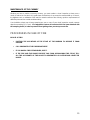
PROCEDURES IN CASE OF FIRE....................................................................23
FREQUENTLY ASKED QUESTIONS............................................................24
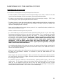
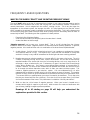
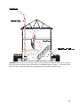
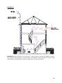
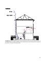
WHAT DO THE WORDS “DRAFT” AND “NEGATIVE PRESSURE” MEAN? .........24
CAN I MODIFY MY STOVE TO INSTALL A GLASS DOOR?......................................30
WHEN DO IN NEED TO REPLACE THE FIREBRICKS? ...........................................30
LIMITED LIFETIME WARRANTY..................................................................31
2

INTRODUCTION
THE DROLET WOOD STOVE MANUAL
SBI INC., one of the most important wood stove and fireplace manufacturers in North America,
congratulates you on your purchase and wishes to help you get maximum satisfaction from the wood stove
you have selected. In the pages that follow, we will give you advices on wood heating and controlled
combustion as well as technical specifications regarding installation, operation and maintenance of the
model you have chosen.
The instructions pertaining to the installation of your wood stove comply with ULC #S627 standards. You
must follow them very carefully in order to eliminate any chance of encountering major problems.
Read this entire manual before you install and use your new stove. If this stove is
not properly installed, a house fire may result. To reduce the risk of fire, follow the
installation instructions. Failure to follow instructions may result in property
damage, bodily injury or even death.
PLEASE CONSULT LOCAL AUTHORITIES, BUILDING DEPARTMENT OR
FIRE MARSHALL ABOUT RESTRICTIONS, INSTALLATION
REQUIREMENTS AND FOR THE NEED TO OBTAIN A PERMIT BEFORE
YOU INSTALL YOUR WOOD STOVE.
KEEP THIS INSTRUCTION MANUAL FOR FUTURE REFERENCE.
WOOD HEATING
Many consumers choose wood as the main or auxiliary energy source for heating their dwelling or
secondary residence. This source of energy has the advantage of being abundant, relatively cheap and
easy to store so that you are assured of energy autonomy for more of less longer periods.
THE CONTROLLED COMBUSTION WOOD STOVE
The main feature of a controlled combustion wood stove is an air tightness that is the most perfect possible,
and must of course be equipped with the most efficient heat exchanger possible in order to transfer
maximum heat to the ambient air. It is generally doubled with firebricks, and it may have a glass door, with
steel or cast iron frame. The main feature that makes it a controlled combustion wood stove remains its air
tightness, which allows the user to control the quantity of oxygen admitted into the wood stove.
The wood will burn slowly if the wood stove draught keys are adjusted in order to reduce the oxygen supply
in the combustion chamber to minimum; on the other hand, wood will burn quickly if the draught keys are
adjusted to admit a larger quantity of oxygen in the combustion chamber.
3

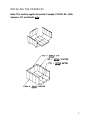
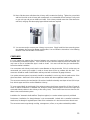
ASSEMBLING THE STOVE
Note: This section applies to models Compak, CS1200, ML, Little
Sawman, RC and Nordic
only.
1- Mount the 4 legs using 2 screws per leg.
2- Mount the ash lip with two screws.
3- Install the heat shield between the front legs,
just above the leg supports.
4- Bend the heat shield slightly to make it fit
between the back legs.
4

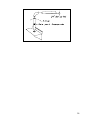
INSTALLING THE FIREBRICKS
Note: This section applies to models Compak, CS1200, ML, Little
Sawman , RC and Nordic
only.
5

INSTALLATION OF YOUR DROLET WOOD STOVE
POSITIONING THE STOVE
It is very important to position the wood stove as close as possible to the chimney, and in an area that will
favor the most efficient heat distribution possible throughout the house. The stove must therefore be
installed in the room where the most time is spent, and in the most spacious room possible. Recall that
wood stoves produce radiating heat, the heat we feel when we are close to a wood stove. A wood stove
also functions by convection, that is through the displacement of hot air accelerated upwards and its
replacement with cooler air. If necessary, the hot air distribution from the stove may be facilitated by a
blower or the installation of floor or wall grids. Except for model FX3000, it is strictly forbidden to install
your wood stove in a mobile home.
Important:
A wood stove must never be installed in a hallway or near a staircase, since it may block the way in case of
fire or fail to respect required clearance.
The wood stove must not be hooked up to a hot air distribution
system since an excessive accumulation of heat may occur.
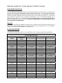
FLOOR PROTECTION
Your woodstove should be placed on a non-combustible surface. Having these minimum specifications.
FLOOR PROTECTION
Models
Thickness of
Sheet
Front Protrusion Side Protrusions Rear Protrusion
Baron 1880sp 1/4" (6mm) 18" (457mm) 8" (203mm) 10" (152mm)
Baron 2000sp 1/4" (6mm) 18" (457mm) 8" (203mm) 10" (152mm)
Cassandra 1/4" (6mm) 18" (457mm) 6" (152mm) 6" (152mm)
Classic 1/4" (6mm) 18" (457mm) 8" (203mm) 8" (203mm)
Compak 1/4" (6mm) 18" (457mm) 8" (203mm) 8" (203mm)
Contempro 1300 1/4" (6mm) 18" (457mm) 8" (203mm) 8" (203mm)
Contempro 1600 1/4" (6mm) 18" (457mm) 8" (203mm) 8" (203mm)
Contempro 2000 1/4" (6mm) 18" (457mm) 8" (203mm) 8" (203mm)
CS1200 1/4" (6mm) 18" (457mm) 8" (203mm) 8" (203mm)
FX 3000 1/4" (6mm) 18" (457mm) 8" (203mm) N/A
Gemini 1200 1/4" (6mm) 18" (457mm) 6" (152mm) 6" (152mm)
Gemini 1500 1/4" (6mm) 18" (457mm) 6" (152mm) 6" (152mm)
Jasper 1/4" (6mm) 18" (457mm) 6" (152mm) 6" (152mm)
Klondike 1/4" (6mm) 18" (457mm) 6" (152mm) 6" (152mm)
Little Sawman 1/4" (6mm) 18" (457mm) 8" (203mm) 8" (203mm)
Lorraine 1/4" (6mm) 18" (457mm) 6" (152mm) 6" (152mm)
ML 1/4" (6mm) 18" (457mm) 6" (152mm) 6" (152mm)
Patriarch 1/4" (6mm) 18" (457mm) 8" (203mm) 8" (203mm)
RC 1/4" (6mm) 18" (457mm) 8" (203mm) 8" (203mm)
Nordic 1/4" (6mm) 18" (457mm) 8" (203mm) 8" (203mm)
Royal Comfort 1/4" (6mm) 18" (457mm) 10" (254mm) 10" (254mm)
Sawman 1/4" (6mm) 18" (457mm) 10" (254mm) 10" (254mm)
Sawyer 1/4" (6mm) 18" (457mm) 8" (203mm) 10" (254mm)
Settler 1/4" (6mm) 18" (457mm) 10" (254mm) 10" (254mm)
Whistler , DLX 1/4" (6mm) 18" (457mm) 6" (152mm) 6" (152mm)
6

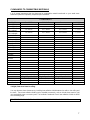
CLEARANCES TO COMBUSTIBLE MATERIALS
It is of utmost importance that the clearances to combustible material mentioned on your wood stove
certification plate be scrupulously respected upon installation.
CLEARANCES
Model Back Wall Side Walls Corners * Height
Baron 1880sp
18" / 610 mm 16" / 406 mm 16" / 406 mm 7' / 2,13 m
Baron 2000sp
24" / 610 mm 16" / 406 mm 16" / 406 mm 7' / 2,13 m
Baron 1880sp
with envelope
15" / 381 mm 26,5’’ / 673mm 26,5’’ / 673mm 7' / 2,13 m
Baron 2000sp
with enveloppe
15" / 381 mm 26,5’’ / 673mm 26,5’’ / 673mm 7' / 2,13 m
Cassandra
16" / 406 mm 16" / 406 mm 16" / 406 mm 7' / 2,13 m
Compak
16" / 406 mm 16" / 406 mm 16" / 406 mm 7' / 2,13 m
Contempro 1300
14" / 355 mm 26" / 660 mm 15" / 381 mm 7' / 2,13 m
Contempro 1600
12" / 305 mm 24" / 610 mm 15" / 381 mm 7' / 2,13 m
Contempro 2000
12" / 305 mm 24" / 610 mm 15" / 381 mm 7' / 2,13 m
CS 1200
16" / 406 mm 16" / 406 mm 16" / 406 mm 7' / 2,13 m
Gemini 1200
16" / 406 mm 16" / 406 mm 16" / 406 mm 7' / 2,13 m
Gemini 1500
16" / 406 mm 16" / 406 mm 16" / 406 mm 7' / 2,13 m
Jasper
16" / 406 mm 16" / 406 mm 16" / 406 mm 7' / 2,13 m
Klondike
16" / 406 mm 16" / 406 mm 16" / 406 mm 7' / 2,13 m
Little Sawman
16" / 406 mm 16" / 406 mm 16" / 406 mm 7' / 2,13 m
Lorraine
16" / 406 mm 16" / 406 mm 16" / 406 mm 7' / 2,13 m
ML
16" / 406 mm 16" / 406 mm 16" / 406 mm 7' / 2,13 m
Patriarch
48" / 1219 mm 36" / 914 mm 24" / 610 mm 7' / 2,13 m
RC
16" / 406 mm 16" / 406 mm 16" / 406 mm 7' / 2,13 m
Nordic
16" / 406 mm 16" / 406 mm 16" / 406 mm 7' / 2,13 m
Sawman
16" / 406 mm 30" / 762 mm 30" / 762 mm 7' / 2,13 m
Sawyer
36" / 914 mm 38" / 965 mm 24" / 610 mm 7' / 2,13 m
Settler
32" / 813 mm 32" / 813 mm 22" / 559 mm 7' / 2,13 m
Whistler, DLX
16" / 406 mm 16" / 406 mm 16" / 406 mm 7' / 2,13 m
Single Pipe / Double Single Pipe / Double Single Pipe / Double
Classic
16" (406mm) / 12" (305mm) 22" (559mm) / 22" (559mm) 11" (279mm) / 11" (279mm) 7' / 2,13 m
Fx 3000
14 1/2"(368mm) / 4 /2"(114mm) 12" (305mm) / 12" (305mm) 4" (102mm) / 4" (102mm) 7' / 2,13 m
Royal Comfort
17" (432mm) / 8" (203mm) 13" (330mm) / 13" (330mm) N/A 7' / 2,13 m
* Height, from stove base to ceiling.
You may decrease these clearances by installing heat radiation shields between the walls or the ceiling and
the stove. These heat radiation shields must be installed permanently, and can include sheet metal, a rigid
non-combustible sheet or a masonry wall. The installation standards of such heat radiation shields are listed
on the following page.
IT IS STRICTLY FORBIDDEN TO PLACE WOOD WITHIN THE MINIMUM CLEARANCES.
7

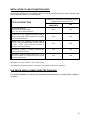
INSTALLATION OF A HEAT RADIATION SHIELD
Following the installation of a heat radiation shield, the clearances mentioned on the stove certification plate
may be reduced as stated in the following table.
Reductions in clearance to a combustible wall (or
ceiling) and the heating device, %
TYPE OF PROTECTION
SIDES AND
REAR\BACK
TOP
Minimal requirements:
0,013" (0,33 mm) sheet metal
with 1" (25.4mm) fire-proof braces
67%** 50%
Ceramic tile or an equivalent fire-proof material
resting on fire-proof brackets spaced 1" (25.4mm)
apart by fire-proof braces
50% 33%
Ceramic tile or an equivalent fire-proof material
built on a fire-proof base resting on sheet metal of
at least 0,013" (0,33 mm) thick spaced 1"
(25.4mm) by fire-proof braces.
67% 50%
Solid bricks, spaced 1" (25.4mm) from the rear
wall using fire-proof braces.
50% N\A
Solid bricks, resting on sheet metal 0,013" (0,33
mm) thick spaced 1" (25.4mm) from the rear wall
using fire-proof braces.
67% N\A
**Example: 15 inches x (100% - 67%) = 4,95 inches.
This reduction in clearance, when in compliance, is accepted by insurance companies.
FOR BARON 1880SP & 2000SP USING THE ENVELOPE
It is strictly forbidden to connect the envelope to existing liners or existing floor registers
or grilles.
8

CHIMNEY
Your wood stove may be hooked up with a prefabricated or masonry chimney. If you are using a prefab
chimney, it must comply with S-629 standards; therefore it must be approved for up to 2100
o
F (650° C) and
have 2" (51 mm) of insulation. It is extremely important that it be installed according to the manufacturer's
specifications.
If you are using a masonry chimney, it is important that it be built in compliance with the specifications of the
National Building Code. It must be lined with refractory bricks, metal or clay tiles sealed together with fire
cement. (Round flues are the most efficient).
The interior diameter of the chimney flue must be identical to that of the stove smoke exhaust. A flue which
is too small may cause draft problems, while a large flue favors rapid cooling of the gas, thus enhancing
creosote build-up and the risk of chimney fires. Current practice requires that the area of the chimney flue
do not exceed the stove exhaust area by more than 35%. For a round pipe, 35% of the area represent
approximately 1” (25 mm) on the diameter. (ex: For a stove with an exhaust of 6”, the chimney flue should
not exceed 7” of diameter.) Note that it is the chimney and not the stove which creates the draft effect; your
stove's performance is directly dependent on an adequate draft from your chimney.
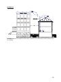
The following recommendations may be useful for the installation of your chimney:
1) It must rise above the roof at least 3' (0,9 m) from the uppermost point of contact.
2) The chimney must exceed any part of the building or other obstruction within a 10' (3,04 m) distance
by a height of 2' (0,60 m).
3) Installation of an interior chimney is always preferable to an exterior chimney. Indeed, the interior
chimney will by definition be hotter than an exterior chimney, being heated up by the ambient air in
the house. Therefore the gases which circulate will cool more slowly thus reducing the build-up of
creosote and the risk of chimney fires.
The draft, which is created by the tendency for hot air to rise, will be better with an interior chimney.
4) You must not install more than one heating unit per chimney flue.
5) The use of a fire-screen at the extremity of the chimney requires regular inspection in order to
insure that it is not obstructed.
STEP BY STEP INSTALLATION OF YOUR CHIMNEY
Note : The way to install your chimney may vary from one chimney manufacturer to another. The
instructions contained in this manual are based on the recommendations of chimney manufacturers whose
products are sold at many Canadian retailers of wood stoves and related heating accessories.
WALL SUPPORT SYSTEM
If your chimney must rise along an outside wall, you need to connect it to your stove through an adjacent
wall. For this type of installation, the following items are normally required :
Chimney
• Suitable lengths of chimney (enough to go up to your roof)
• An adjustable wall support
• A wall thimble
• An adequate number of wall bands (one for every 8 feet of chimney, excluding the roof portion)
• A stove pipe adapter
• One insulated tee & plug
• A chimney cap.
9

• Roof guys (if required)
Stove pipe
• An adequate number of stove pipe sections.
• A 90
o
elbow
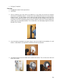
1- Start by positioning your stove where you would like it to go, taking into account the minimum
clearances to combustible material. You will then be able to determine where the chimney will pass
through the wall. You will probably have to adjust the stove position slightly to ensure that your
chimney will run between the studs. You can use a stud finder to locate the studs. Use a spoke saw
or jig saw to cut a hole, remembering that you need to maintain a clearance of 2 inches between the
chimney and any combustible materials. For concrete walls, cut a hole slightly larger than the outer
diameter of the chimney.
2- Once the opening completed, you need to frame in the area to allow for the installation of a wall
thimble. A wall thimble is not required for installations through concrete walls.
3- You must first secure the wall thimble into the exterior wall surface. Then, do the same inside and
fasten the trim plate.
10

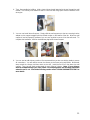
4- Then, from outside the building, slide a short chimney length (attached to the tee) through the wall
thimble. The chimney must extend at least 3 inches into the living space where it attaches to the
stove pipe.
5- You can now install the wall support. Simply slide the wall support up to the tee, ensuring that the
adapter on the support engages with the female coupler on the bottom of the tee. When the wall
support is level and properly positioned, you can use lag bolts to secure it into the wall studs. TO
complete the installation, install an insulated tee plug below the wall support.
6- You can start to add chimney sections. We recommend that you also use locking bands to secure
all connections. You will need to secure the chimney to the house using wall bands. Wall bands
wrap around the chimney and then attach to the wall. Install the first one 3 feet above the wall
support. Then, you will need another band for each 8 feet of chimney. Note: if your chimney
must be installed through your soffit, install a roof flashing above and finishing plate below
where the roof is cut. Consult the following section called “CEILING SUPPORT SYSTEM” for
more details.
11

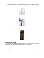
7- Authorities require that the chimney extend not less than 3 feet above the highest point where it
passes through the roof of a building and not less than 2 feet above any portion of the building
within 10 feet. If the chimney extends more than 5 feet above the roof deck, roof guys with
telescoping legs and draw bands are required.
8- Finally, twist on your rain cap and you can head back inside.
9- You are now ready to connect your chimney to your stove. Simply install the inter-connecting stove
pipe between the stove pipe adapter and the stove. You can follow the instructions in the following
sections of this manual under « COUPLINGS ».
CEILING SUPPORT SYSTEM
If your chimney must rise inside the house and go through the ceiling, you need to connect it to your stove at
the ceiling level. For this type of installation, the following items are normally required :
Chimney
• An adequate number of chimney sections (enough to go up to your roof)
• A ceiling support kit with stove pipe adapter
• An attic insulation shield
• A roof flashing kit
• A chimney cap
• Roof guys (if necessary)
12

Stove pipe
• Suitable lengths of stove pipe
1- Place your stove where you would like it located and use a plumb line to mark the ceiling directly
above your stove flue. You will probably have to adjust this position slightly to ensure that your
chimney will run between the joists. You can use a stud finder to locate the joists. You also need to
take into account the minimum clearances to combustible materials. After you have determined
where the chimney will go through the ceiling, use a spoke saw or power jig saw to cut a hole,
remembering that you need a minimum 2-inch clearance between the chimney and any combustible
materials. Depending on whether you have a one or two story structure, you will need to cut a
matching hole through the floor of the attic or second floor living space.
2- Before you install the ceiling support, you need to frame the area.
3- To install the ceiling support, just slide the assembly into the framed opening from below. Once you
ensure that the finishing plate is flush with the underside of the ceiling and assembly is level, secure
it with screws.
13

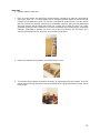
4- Once the support is secure, you can begin to assemble the chimney by lowering the first section into
the support. Make sure that the male coupler is pointing upwards, as indicated by the arrow on the
chimney label.
5- Then, from beneath the support, insert the stove pipe adapter and twist-lock it into place.
6- Now, you can add additional chimney sections. Continue adding chimney lengths until a height of
about 2 fet below the next ceiling level. An attic insulation shield must be installed where a chimney
passes from a lower living space into an upper living space or attic space. It is designed to keep
insulation materials away from the chimney. A second attic insulation shield must be installed if
your chimney passes from a lower living space into an upper living space. As wee, you must
enclose all sections of the chimney where is passes through a living space. Elbows (15
o
or 30
o)
are
used when you need to offset your chimney to clear an obstruction or to avoid having to cut joists.
7- Once you have cut through your roof and framed the joists, it is time to work outdoors. Authorities
require that the chimney extend not less than 3 feet above the highest point where it passes through
the roof of a building and not less that 2 feet above any portion of the building within 10 feet. You will
need to install a roof flashing. The roof flashing slides over your chimney pipe and goes under your
shingles. Once you have done that, check that everything is plumb, and nail the flashing into the
roof deck. Seal the joint between the shingles and the plate with silicone.
14

10- Next, slide the storm collar down the chimney until it contacts the flashing. Tighten the nut and bolt
and seal the collar to the chimney with a waterproof, non-combustible silicone sealant. Finally, twist
on your rain cap and you can head back inside. If the chimney extends more than 5 feet above the
roof deck, roof guys with telescoping legs and draw bands are required.
11- You are now ready to connect your chimney to your stove. Simply install the inter-connecting stove
pipe between the stove pipe adapter and the stove. You can follow the instructions in the following
sections of this manual under “COUPLINGS”.
COUPLINGS
It is very important to measure the clearance between your connectors (commonly called stove pipe) and
the surrounding combustible surfaces. If the normal 18 inches clearance required cannot be obtained, you
may have to use an insulated flue pipe in order to install. You must read the flue pipe manufacturer's
instructions before installation.
Your connectors and chimney must have the same diameter as the stove outlet. If this is not the case, we
recommend you contact your supplier in order to insure there will be no problem with the draft. Your
connectors should be made of aluminized or ordinary steel with a minimum 24 gauge thickness.
Your smoke exhaust system (connectors) should be assembled in such a way that the male section of the
pipes faces down. Attach each of the sections to one another with three equidistant metal screws.
The connectors must be short and straight. All sections installed horizontally must slope at least 1/4 inch per
foot, with the upper end of the section toward the chimney.
To insure a good draft, the total length of the exhaust system should never exceed 8 to 10 feet. (Except for
cases of vertical installations or cathedral-roof, where the smoke exhaust system can be much longer and
connected without problem to the chimney at the ceiling level). There should never be more than one 90°
elbow in the smoke exhaust system.
Installation of a "barometric draft stabilizer" (fireplace register) on a smoke exhaust system is prohibited.
Furthermore, installation of a draught damper is not recommended. Indeed, with a controlled combustion
wood stove, the draught is regulated upon intake of the combustion air in the stove and not at the exhaust.
The connectors must not go through a ceiling, a storage area, a floor, or any other combustible partition.
15

16

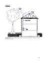
EXTERIOR AIR INTAKE
Since the FX 3000 has been approved for installation in mobile homes, it is equipped with an optional
exterior intake. The procedure for installation of the exterior air intake is as follows:
A) Rear Wall Connection
Determine the position on the wall, cut out a 6" (152 mm) diameter hole, position the screen from
outside and join the insulated duct from the screen to the attachment flange underneath the stove.
B) Floor Connection
Put a mark on the floor, at the center of the attachment flange underneath the stove.
Move the stove, and make a hole with a 6" (152 mm) inch radius around the center of the mark.
Position the ventilation screen from outside and attach the insulated duct to the attachment flange
underneath the stove.
NOTE: Spacing between the wall or the floor and the insulated duct will be sealed with silicone in
order to insure continuity to the vapor barrier.
Then attach the unit to the floor using the two screws provided for this purpose
.
AIR CIRCULATION SYSTEM
In order to improve air circulation in the room where the wood stove is installed, certain options are available
for specific stove models.
Blower: A variable speed-control blower is available. Please note that there are two types of blowers
available, depending on the stove model you have. If the hole at the back of your stove
(where the blower needs to be hooked-up) has a round outlet, you will need blower
#AC05520. If there is a rectangular knock-off, you will need blower #AC02050.
Thermodisc: Available on most models, the thermodisc is a sensor that connects to the blower`s
electrical supply cord, and it will start the blower when the stove`s temperature reaches
120° F (49
o
C) and cut off power when the stove cools down below 100° F (37
o
C).
Information regarding installation of the thermodisc is included with the device.
The blower system includes some particularities for specific stove models: For the Compak,
CS1200, Little Sawman, ML, Nordic and RC, an adaptor is required in order to install the
blower. That adaptor is included with the stove, when purchased.
17

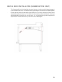
BAFFLE BRICK INSTALLATION (SAWMAN STOVE ONLY)
- The Sawman baffle brick is shipped with the stove. However, in order to avoid shipping damages, it
is not installed on the stove. You need to install it by following the instructions on the drawing below.
- Please note that heating the stove without the baffle brick can seriously damage the firebox and will
automatically nullify your warranty. The baffle brick will eventually need to be replaced. How long it
will take depends on how often you use your stove. It is very important that you do not postpone the
replacement of the baffle brick when you see that it starts to disintegrate.
18

OPERATING YOUR DROLET WOOD STOVE
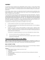
FUEL
Your stove was designed to burn wood only. No other type of fuel should be used. Waste and other
flammable materials are prohibited. Any type of wood may be used in your stove, but specific varieties have
better energy yields than others. Please consult the following table in order to make the best possible
choice.
AVERAGE ENERGY YIELD OF ONE AIR DRIED CORD OF CUT WOOD
High Energy Yield
MBTU/cord MBTU/cord MBTU/cord
Oak 29 Sugar Maple 28 Beech 26
Medium Energy Yield
MBTU/cord MBTU/cord MBTU/cord
Yellow birch 25 Ash 24 Elm 23
Larch (Tamarack) 23 Red Maple 23 Douglas red fir 23
Silver birch 22
Low Energy Yield
MBTU/cord MBTU/cord MBTU/cord
Alder 18 Poplar 17 Hemlock 17
Spruce 17 Pine 17 Bass 16
Fir 13
Data provided by Energy, Mines and Resources - Canada
It is EXTREMELY IMPORTANT that you only use DRY WOOD in your wood stove. The wood must have
dried for 9 to 15 months, so that the humidity content is reduced below 20% of the weight of the log. It is
very important to keep in mind that even if the wood has been cut for one, two or even more years, it is not
necessarily dry, especially if it has been stored in poor conditions. Under extreme conditions, it may even
have rotten instead of drying. This point cannot be overstressed enough; the vast majority of the problems
related to the operation of a wood stove is caused by the fact that the wood used was too damp or had dried
in poor conditions. These problems can be:
- Ignition problems.
- Creosote build-up causing chimney fires.
- Low energy yield.
- Blackened glass door.
- Incomplete log combustion.
- Etc.
19

Smaller pieces of wood will dry faster. All logs exceeding 6" (152 mm) should be split. The wood should be
stored in a place where the grass is not too long, in such a way that prevailing winds may circulate through
the fire logs. A 24" to 48" (610 mm to 1219 mm) air space should be left between each row of fire logs,
which should be placed in the sunniest location possible. If the wood must be stored outside, the upper
layer of wood should be protected from rain and bad weather but not the sides.
Before your first fire:
- Check if firebricks are lined-up properly.
- If applicable, remove the plastic protector covering the gold trims.
- Make sure that the chimney and flue pipe are well installed according to specifications.
- Respect all clearances to combustibles and floor protection according to the unit you have chosen.
- If you are not sure that your installation is adequate, do not hesitate to contact your Drolet dealer.
IGNITION
The installation of a log cradle is NOT RECOMMENDED in your DROLET wood stove.
After making sure that the stove air intake controls are fully open, place several rumpled sheets of paper at
the center of the firebox. Place 8 to 10 pieces of small dry kindling wood over the paper in the form of a tent.
You may also place a few pieces of firewood, but choose them as small as possible. No chemical product
(or accelerant) should be used to light the fire.
Before igniting the paper and kindling wood, it is recommended that you warm up the chimney. This is done
in order to avoid backdraft problems often due to negative pressure in the house; cold air from the outside
tends to penetrate into the house by the chimney and creates a “clog” effect.
If such is the case, open a window slightly near the stove and twist together a few sheets of newspaper into
a torch. Light up this paper torch and hold it as close as possible to the mouth of the pipe inside the firebox
to warm up the chimney. Once the updraft movement is initiated, you are ready to ignite the stove by
lighting the paper and kindling wood inside the combustion chamber.
We advise you to leave the door slightly open (a few inches) for a 5 to 10 minutes period, under supervision,
in order to allow for good combustion. After this time, you may close the door and progressively adjust the
air controls to obtain the desired temperature.
CAUTION:
- Do not leave the stove unattended when the door is slightly open.
- When the stove is used for the first time, intense fire is prohibited in order to allow adequate curing
of the paint covering the stove and to prevent a "thermal shock" which may remove or whiten the
paint.
- Make sure the room is well ventilated, to remove the bad odors emitted from the paint, during the
first two or three hours of usage.
- Never heat the stove outside the house before you install it. It is impossible to adequately monitor
the combustion intensity, which may cause overheating and a thermal shock to the paint.
- Never use fluid or chemical products to ignite the fire.
- Do not burn wastes, flammable fluid such as gasoline, naphtha or motor oil.
20
Page is loading ...
Page is loading ...
Page is loading ...
Page is loading ...
Page is loading ...
Page is loading ...
Page is loading ...
Page is loading ...
Page is loading ...
Page is loading ...
Page is loading ...
-
 1
1
-
 2
2
-
 3
3
-
 4
4
-
 5
5
-
 6
6
-
 7
7
-
 8
8
-
 9
9
-
 10
10
-
 11
11
-
 12
12
-
 13
13
-
 14
14
-
 15
15
-
 16
16
-
 17
17
-
 18
18
-
 19
19
-
 20
20
-
 21
21
-
 22
22
-
 23
23
-
 24
24
-
 25
25
-
 26
26
-
 27
27
-
 28
28
-
 29
29
-
 30
30
-
 31
31


Ask a question and I''ll find the answer in the document
Finding information in a document is now easier with AI
Related papers
-
 Drolet GEMINI 1200 WOOD STOVE User manual
-
 Drolet 45109A User manual
-
Drolet Escape 1800 User manual
-
 Drolet SAWMAN WOOD STOVE User manual
-
 Drolet SAHARA WOOD STOVE User manual
-
-
 Drolet Stove 45284 User manual
-
Drolet UL 1482 User manual
-
 Drolet 1800 EPA User manual
-
 Drolet DB03505 User manual


Other documents
-
Century 45398A User manual
-
-
Draper 1000 User manual
-
 The Forever Cap FPC1824 Installation guide
-
 Century Heating FW2470 WOOD STOVE User manual
-
 Century Heating FW2470 WOOD STOVE User manual
-
-
GLAWNING 45 Degree Tent Stove Flashing Kit Operating instructions
-
Vogelzang TR001WS Installation guide
-
 Amesti Nordic 360 Owner's manual


