Page is loading ...

PowCon
Arc Stud 625
Welding System
R
Process
Description
Arc Welding Power Source
OM-216 244J
2007−03
Stud (SW) Welding
™
File: STUD WELDING (SW)
Visit our website at
www.MillerWelds.com

Miller Electric manufactures a full line
of welders and welding related equipment.
For information on other quality Miller
products, contact your local Miller distributor to receive the latest full
line catalog or individual specification sheets. To locate your nearest
distributor or service agency call 1-800-4-A-Miller, or visit us at
www.MillerWelds.com on the web.
Thank you and congratulations on choosing Miller. Now you can get
the job done and get it done right. We know you don’t have time to do
it any other way.
That’s why when Niels Miller first started building arc welders in 1929,
he made sure his products offered long-lasting value and superior
quality. Like you, his customers couldn’t afford anything less. Miller
products had to be more than the best they could be. They had to be the
best you could buy.
Today, the people that build and sell Miller products continue the
tradition. They’re just as committed to providing equipment and service
that meets the high standards of quality and value established in 1929.
This Owner’s Manual is designed to help you get the most out of your
Miller products. Please take time to read the Safety precautions. They
will help you protect yourself against potential hazards on the worksite.
We’ve made installation and operation quick
and easy. With Miller you can count on years
of reliable service with proper maintenance.
And if for some reason the unit needs repair,
there’s a Troubleshooting section that will
help you figure out what the problem is. The
parts list will then help you to decide the
exact part you may need to fix the problem.
Warranty and service information for your
particular model are also provided.
Miller is the first welding
equipment manufacturer in
the U.S.A. to be registered to
the ISO 9001:2000 Quality
System Standard.
Working as hard as you do
− every power source from
Miller is backed by the most
hassle-free warranty in the
business.
From Miller to You
Mil_Thank 4/05

TABLE OF CONTENTS
SECTION 1 − SAFETY PRECAUTIONS - READ BEFORE USING 1 . . . . . . . . . . . . . . . . . . . . . . . . . . . . . . . . . . .
1-1. Symbol Usage 1 . . . . . . . . . . . . . . . . . . . . . . . . . . . . . . . . . . . . . . . . . . . . . . . . . . . . . . . . . . . . . . . . . . . . . . . .
1-2. Arc Welding Hazards 1 . . . . . . . . . . . . . . . . . . . . . . . . . . . . . . . . . . . . . . . . . . . . . . . . . . . . . . . . . . . . . . . . . .
1-3. Additional Symbols For Installation, Operation, And Maintenance 3 . . . . . . . . . . . . . . . . . . . . . . . . . . . . .
1-4. California Proposition 65 Warnings 3 . . . . . . . . . . . . . . . . . . . . . . . . . . . . . . . . . . . . . . . . . . . . . . . . . . . . . . .
1-5. Principal Safety Standards 4 . . . . . . . . . . . . . . . . . . . . . . . . . . . . . . . . . . . . . . . . . . . . . . . . . . . . . . . . . . . . .
1-6. EMF Information 4 . . . . . . . . . . . . . . . . . . . . . . . . . . . . . . . . . . . . . . . . . . . . . . . . . . . . . . . . . . . . . . . . . . . . . .
SECTION 2 − CONSIGNES DE SÉCURITÉ − LIRE AVANT UTILISATION 5 . . . . . . . . . . . . . . . . . . . . . . . . . . . .
2-1. Symboles utilisés 5 . . . . . . . . . . . . . . . . . . . . . . . . . . . . . . . . . . . . . . . . . . . . . . . . . . . . . . . . . . . . . . . . . . . . .
2-2. Dangers relatifs au soudage à l’arc 5 . . . . . . . . . . . . . . . . . . . . . . . . . . . . . . . . . . . . . . . . . . . . . . . . . . . . . .
2-3. Dangers supplémentaires en relation avec l’installation, le fonctionnement et la maintenance 7 . . . . . .
2-4. Proposition californienne 65 Avertissements 7 . . . . . . . . . . . . . . . . . . . . . . . . . . . . . . . . . . . . . . . . . . . . . . .
2-5. Principales normes de sécurité 8 . . . . . . . . . . . . . . . . . . . . . . . . . . . . . . . . . . . . . . . . . . . . . . . . . . . . . . . . . .
2-6. Information EMF 8 . . . . . . . . . . . . . . . . . . . . . . . . . . . . . . . . . . . . . . . . . . . . . . . . . . . . . . . . . . . . . . . . . . . . . .
SECTION 3 − INTRODUCTION 9 . . . . . . . . . . . . . . . . . . . . . . . . . . . . . . . . . . . . . . . . . . . . . . . . . . . . . . . . . . . . . . . . .
3-1. Specifications 9 . . . . . . . . . . . . . . . . . . . . . . . . . . . . . . . . . . . . . . . . . . . . . . . . . . . . . . . . . . . . . . . . . . . . . . . .
3-2. Duty Cycle And Overheating 9 . . . . . . . . . . . . . . . . . . . . . . . . . . . . . . . . . . . . . . . . . . . . . . . . . . . . . . . . . . . .
SECTION 4 − INSTALLATION - POWER SOURCE 10 . . . . . . . . . . . . . . . . . . . . . . . . . . . . . . . . . . . . . . . . . . . . . . . .
4-1. Selecting a Location 10 . . . . . . . . . . . . . . . . . . . . . . . . . . . . . . . . . . . . . . . . . . . . . . . . . . . . . . . . . . . . . . . . . . .
4-2. Electrical Service Guide 11 . . . . . . . . . . . . . . . . . . . . . . . . . . . . . . . . . . . . . . . . . . . . . . . . . . . . . . . . . . . . . . . .
4-3. Weld Output Receptacles And Selecting Cable Sizes 12 . . . . . . . . . . . . . . . . . . . . . . . . . . . . . . . . . . . . . . .
4-4. Connecting 3-Phase Input Power 13 . . . . . . . . . . . . . . . . . . . . . . . . . . . . . . . . . . . . . . . . . . . . . . . . . . . . . . . .
4-5. Circuit Breaker 14 . . . . . . . . . . . . . . . . . . . . . . . . . . . . . . . . . . . . . . . . . . . . . . . . . . . . . . . . . . . . . . . . . . . . . . .
4-6. 4 Pin Receptacle Information 14 . . . . . . . . . . . . . . . . . . . . . . . . . . . . . . . . . . . . . . . . . . . . . . . . . . . . . . . . . . . .
4-7. Rack Mounting 14 . . . . . . . . . . . . . . . . . . . . . . . . . . . . . . . . . . . . . . . . . . . . . . . . . . . . . . . . . . . . . . . . . . . . . . .
SECTION 5 − INSTALLATION - STUD GUN 15 . . . . . . . . . . . . . . . . . . . . . . . . . . . . . . . . . . . . . . . . . . . . . . . . . . . . . .
5-1. Chuck Installation 15 . . . . . . . . . . . . . . . . . . . . . . . . . . . . . . . . . . . . . . . . . . . . . . . . . . . . . . . . . . . . . . . . . . . . .
5-2. Chuck Removal 15 . . . . . . . . . . . . . . . . . . . . . . . . . . . . . . . . . . . . . . . . . . . . . . . . . . . . . . . . . . . . . . . . . . . . . .
5-3. Foot and Leg Setup 16 . . . . . . . . . . . . . . . . . . . . . . . . . . . . . . . . . . . . . . . . . . . . . . . . . . . . . . . . . . . . . . . . . . .
5-4. Ferrule Grip / Spark Shield Removal and Installation 16 . . . . . . . . . . . . . . . . . . . . . . . . . . . . . . . . . . . . . . . .
5-5. Foot Alignment 17 . . . . . . . . . . . . . . . . . . . . . . . . . . . . . . . . . . . . . . . . . . . . . . . . . . . . . . . . . . . . . . . . . . . . . . .
5-6. Connecting Stud Gun and Work Clamp to Power Source 17 . . . . . . . . . . . . . . . . . . . . . . . . . . . . . . . . . . . .
5-7. Plunge Adjustment 18 . . . . . . . . . . . . . . . . . . . . . . . . . . . . . . . . . . . . . . . . . . . . . . . . . . . . . . . . . . . . . . . . . . . .
5-8. Adjusting Stud Lift 19 . . . . . . . . . . . . . . . . . . . . . . . . . . . . . . . . . . . . . . . . . . . . . . . . . . . . . . . . . . . . . . . . . . . . .
SECTION 6 − OPERATION - POWER SOURCE 20 . . . . . . . . . . . . . . . . . . . . . . . . . . . . . . . . . . . . . . . . . . . . . . . . . .
6-1. Front Panel Controls 20 . . . . . . . . . . . . . . . . . . . . . . . . . . . . . . . . . . . . . . . . . . . . . . . . . . . . . . . . . . . . . . . . . . .
6-2. Time/Amperage Control 22 . . . . . . . . . . . . . . . . . . . . . . . . . . . . . . . . . . . . . . . . . . . . . . . . . . . . . . . . . . . . . . . .
SECTION 7 − OPERATION - STUD GUN 24 . . . . . . . . . . . . . . . . . . . . . . . . . . . . . . . . . . . . . . . . . . . . . . . . . . . . . . . .
7-1. Stud Gun Tool Functions 24 . . . . . . . . . . . . . . . . . . . . . . . . . . . . . . . . . . . . . . . . . . . . . . . . . . . . . . . . . . . . . . .
7-2. Stud Welding Procedures 24 . . . . . . . . . . . . . . . . . . . . . . . . . . . . . . . . . . . . . . . . . . . . . . . . . . . . . . . . . . . . . .
7-3. Welding Sequence 25 . . . . . . . . . . . . . . . . . . . . . . . . . . . . . . . . . . . . . . . . . . . . . . . . . . . . . . . . . . . . . . . . . . . .
7-4. Recommended Settings 25 . . . . . . . . . . . . . . . . . . . . . . . . . . . . . . . . . . . . . . . . . . . . . . . . . . . . . . . . . . . . . . . .
SECTION 8 − MAINTENANCE & TROUBLESHOOTING 26 . . . . . . . . . . . . . . . . . . . . . . . . . . . . . . . . . . . . . . . . . . .
8-1. Routine Maintenance 26 . . . . . . . . . . . . . . . . . . . . . . . . . . . . . . . . . . . . . . . . . . . . . . . . . . . . . . . . . . . . . . . . . .
8-2. Blowing Out Inside Of Unit 26 . . . . . . . . . . . . . . . . . . . . . . . . . . . . . . . . . . . . . . . . . . . . . . . . . . . . . . . . . . . . . .
8-3. Maintenance Procedures for Stud Gun 28 . . . . . . . . . . . . . . . . . . . . . . . . . . . . . . . . . . . . . . . . . . . . . . . . . . .
8-4. Troubleshooting Help Aids 30 . . . . . . . . . . . . . . . . . . . . . . . . . . . . . . . . . . . . . . . . . . . . . . . . . . . . . . . . . . . . . .
8-5. Troubleshooting - Power Source 30 . . . . . . . . . . . . . . . . . . . . . . . . . . . . . . . . . . . . . . . . . . . . . . . . . . . . . . . . .
8-6. Troubleshooting - Stud Gun 31 . . . . . . . . . . . . . . . . . . . . . . . . . . . . . . . . . . . . . . . . . . . . . . . . . . . . . . . . . . . . .
SECTION 9 − ELECTRICAL DIAGRAMS 33 . . . . . . . . . . . . . . . . . . . . . . . . . . . . . . . . . . . . . . . . . . . . . . . . . . . . . . . .
SECTION 10 − PARTS LIST FOR POWER SOURCE 34 . . . . . . . . . . . . . . . . . . . . . . . . . . . . . . . . . . . . . . . . . . . . . .
SECTION 11 − PARTS LIST FOR STUD GUN 38 . . . . . . . . . . . . . . . . . . . . . . . . . . . . . . . . . . . . . . . . . . . . . . . . . . . .
SECTION 12 − OPTIONS AND ACCESSORIES 40 . . . . . . . . . . . . . . . . . . . . . . . . . . . . . . . . . . . . . . . . . . . . . . . . . .

OM-216 244 Page 1
SECTION 1 − SAFETY PRECAUTIONS - READ BEFORE USING
som _3/05
Y Warning: Protect yourself and others from injury — read and follow these precautions.
1-1. Symbol Usage
Means Warning! Watch Out! There are possible hazards
with this procedure! The possible hazards are shown in
the adjoining symbols.
Y Marks a special safety message.
. Means “Note”; not safety related.
This group of symbols means Warning! Watch Out! possible
ELECTRIC SHOCK, MOVING PARTS, and HOT PARTS hazards.
Consult symbols and related instructions below for necessary actions
to avoid the hazards.
1-2. Arc Welding Hazards
Y The symbols shown below are used throughout this manual to
call attention to and identify possible hazards. When you see
the symbol, watch out, and follow the related instructions to
avoid the hazard. The safety information given below is only
a summary of the more complete safety information found in
the Safety Standards listed in Section 1-5. Read and follow all
Safety Standards.
Y Only qualified persons should install, operate, maintain, and
repair this unit.
Y During operation, keep everybody, especially children, away.
ELECTRIC SHOCK can kill.
Touching live electrical parts can cause fatal shocks
or severe burns. The electrode and work circuit is
electrically live whenever the output is on. The input
power circuit and machine internal circuits are also
live when power is on. In semiautomatic or automatic wire welding, the
wire, wire reel, drive roll housing, and all metal parts touching the
welding wire are electrically live. Incorrectly installed or improperly
grounded equipment is a hazard.
D Do not touch live electrical parts.
D Wear dry, hole-free insulating gloves and body protection.
D Insulate yourself from work and ground using dry insulating mats
or covers big enough to prevent any physical contact with the work
or ground.
D Do not use AC output in damp areas, if movement is confined, or if
there is a danger of falling.
D Use AC output ONLY if required for the welding process.
D If AC output is required, use remote output control if present on
unit.
D Additional safety precautions are required when any of the follow-
ing electrically hazardous conditions are present: in damp
locations or while wearing wet clothing; on metal structures such
as floors, gratings, or scaffolds; when in cramped positions such
as sitting, kneeling, or lying; or when there is a high risk of unavoid-
able or accidental contact with the workpiece or ground. For these
conditions, use the following equipment in order presented: 1) a
semiautomatic DC constant voltage (wire) welder, 2) a DC manual
(stick) welder, or 3) an AC welder with reduced open-circuit volt-
age. In most situations, use of a DC, constant voltage wire welder
is recommended. And, do not work alone!
D Disconnect input power or stop engine before installing or
servicing this equipment. Lockout/tagout input power according to
OSHA 29 CFR 1910.147 (see Safety Standards).
D Properly install and ground this equipment according to its
Owner’s Manual and national, state, and local codes.
D Always verify the supply ground − check and be sure that input
power cord ground wire is properly connected to ground terminal in
disconnect box or that cord plug is connected to a properly
grounded receptacle outlet.
D When making input connections, attach proper grounding conduc-
tor first − double-check connections.
D Frequently inspect input power cord for damage or bare wiring −
replace cord immediately if damaged − bare wiring can kill.
D Turn off all equipment when not in use.
D Do not use worn, damaged, undersized, or poorly spliced cables.
D Do not drape cables over your body.
D If earth grounding of the workpiece is required, ground it directly
with a separate cable.
D Do not touch electrode if you are in contact with the work, ground,
or another electrode from a different machine.
D Do not touch electrode holders connected to two welding ma-
chines at the same time since double open-circuit voltage will be
present.
D Use only well-maintained equipment. Repair or replace damaged
parts at once. Maintain unit according to manual.
D Wear a safety harness if working above floor level.
D Keep all panels and covers securely in place.
D Clamp work cable with good metal-to-metal contact to workpiece
or worktable as near the weld as practical.
D Insulate work clamp when not connected to workpiece to prevent
contact with any metal object.
D Do not connect more than one electrode or work cable to any
single weld output terminal.
SIGNIFICANT DC VOLTAGE exists in inverter-type
welding power sources after removal of input
power.
D Turn Off inverter, disconnect input power, and discharge input
capacitors according to instructions in Maintenance Section
before touching any parts.
Welding produces fumes and gases. Breathing
these fumes and gases can be hazardous to your
health.
FUMES AND GASES can be hazardous.
D Keep your head out of the fumes. Do not breathe the fumes.
D If inside, ventilate the area and/or use local forced ventilation at the
arc to remove welding fumes and gases.
D If ventilation is poor, wear an approved air-supplied respirator.
D Read and understand the Material Safety Data Sheets (MSDSs)
and the manufacturer’s instructions for metals, consumables,
coatings, cleaners, and degreasers.
D Work in a confined space only if it is well ventilated, or while
wearing an air-supplied respirator. Always have a trained watch-
person nearby. Welding fumes and gases can displace air and
lower the oxygen level causing injury or death. Be sure the breath-
ing air is safe.
D Do not weld in locations near degreasing, cleaning, or spraying op-
erations. The heat and rays of the arc can react with vapors to form
highly toxic and irritating gases.
D Do not weld on coated metals, such as galvanized, lead, or
cadmium plated steel, unless the coating is removed from the weld
area, the area is well ventilated, and while wearing an air-supplied
respirator. The coatings and any metals containing these elements
can give off toxic fumes if welded.

OM-216 244 Page 2
Arc rays from the welding process produce intense
visible and invisible (ultraviolet and infrared) rays
that can burn eyes and skin. Sparks fly off from the
weld.
ARC RAYS can burn eyes and skin.
D Wear an approved welding helmet fitted with a proper shade of fil-
ter lenses to protect your face and eyes when welding or watching
(see ANSI Z49.1 and Z87.1 listed in Safety Standards).
D Wear approved safety glasses with side shields under your
helmet.
D Use protective screens or barriers to protect others from flash,
glare and sparks; warn others not to watch the arc.
D Wear protective clothing made from durable, flame-resistant mate-
rial (leather, heavy cotton, or wool) and foot protection.
Welding on closed containers, such as tanks,
drums, or pipes, can cause them to blow up. Sparks
can fly off from the welding arc. The flying sparks, hot
workpiece, and hot equipment can cause fires and
burns. Accidental contact of electrode to metal objects can cause
sparks, explosion, overheating, or fire. Check and be sure the area is
safe before doing any welding.
WELDING can cause fire or explosion.
D Remove all flammables within 35 ft (10.7 m) of the welding arc. If
this is not possible, tightly cover them with approved covers.
D Do not weld where flying sparks can strike flammable material.
D Protect yourself and others from flying sparks and hot metal.
D Be alert that welding sparks and hot materials from welding can
easily go through small cracks and openings to adjacent areas.
D Watch for fire, and keep a fire extinguisher nearby.
D Be aware that welding on a ceiling, floor, bulkhead, or partition can
cause fire on the hidden side.
D Do not weld on closed containers such as tanks, drums, or pipes,
unless they are properly prepared according to AWS F4.1 (see
Safety Standards).
D Connect work cable to the work as close to the welding area as
practical to prevent welding current from traveling long, possibly
unknown paths and causing electric shock, sparks, and fire
hazards.
D Do not use welder to thaw frozen pipes.
D Remove stick electrode from holder or cut off welding wire at
contact tip when not in use.
D Wear oil-free protective garments such as leather gloves, heavy
shirt, cuffless trousers, high shoes, and a cap.
D Remove any combustibles, such as a butane lighter or matches,
from your person before doing any welding.
D Follow requirements in OSHA 1910.252 (a) (2) (iv) and NFPA 51B
for hot work and have a fire watcher and extinguisher nearby.
FLYING METAL can injure eyes.
D Welding, chipping, wire brushing, and grinding
cause sparks and flying metal. As welds cool,
they can throw off slag.
D Wear approved safety glasses with side
shields even under your welding helmet.
BUILDUP OF GAS can injure or kill.
D Shut off shielding gas supply when not in use.
D Always ventilate confined spaces or use
approved air-supplied respirator.
HOT PARTS can cause severe burns.
D Do not touch hot parts bare handed.
D Allow cooling period before working on gun or
torch.
D To handle hot parts, use proper tools and/or
wear heavy, insulated welding gloves and
clothing to prevent burns.
MAGNETIC FIELDS can affect pacemakers.
D Pacemaker wearers keep away.
D Wearers should consult their doctor before
going near arc welding, gouging, or spot
welding operations.
NOISE can damage hearing.
Noise from some processes or equipment can
damage hearing.
D Wear approved ear protection if noise level is
high.
Shielding gas cylinders contain gas under high
pressure. If damaged, a cylinder can explode. Since
gas cylinders are normally part of the welding
process, be sure to treat them carefully.
CYLINDERS can explode if damaged.
D Protect compressed gas cylinders from excessive heat, mechani-
cal shocks, physical damage, slag, open flames, sparks, and arcs.
D Install cylinders in an upright position by securing to a stationary
support or cylinder rack to prevent falling or tipping.
D Keep cylinders away from any welding or other electrical circuits.
D Never drape a welding torch over a gas cylinder.
D Never allow a welding electrode to touch any cylinder.
D Never weld on a pressurized cylinder − explosion will result.
D Use only correct shielding gas cylinders, regulators, hoses, and fit-
tings designed for the specific application; maintain them and
associated parts in good condition.
D Turn face away from valve outlet when opening cylinder valve.
D Keep protective cap in place over valve except when cylinder is in
use or connected for use.
D Use the right equipment, correct procedures, and sufficient num-
ber of persons to lift and move cylinders.
D Read and follow instructions on compressed gas cylinders,
associated equipment, and Compressed Gas Association (CGA)
publication P-1 listed in Safety Standards.

OM-216 244 Page 3
1-3. Additional Symbols For Installation, Operation, And Maintenance
FIRE OR EXPLOSION hazard.
D Do not install or place unit on, over, or near
combustible surfaces.
D Do not install unit near flammables.
D Do not overload building wiring − be sure power supply system is
properly sized, rated, and protected to handle this unit.
FALLING UNIT can cause injury.
D Use lifting eye to lift unit only, NOT running
gear, gas cylinders, or any other accessories.
D Use equipment of adequate capacity to lift and
support unit.
D If using lift forks to move unit, be sure forks are
long enough to extend beyond opposite side of
unit.
OVERUSE can cause OVERHEATING
D Allow cooling period; follow rated duty cycle.
D Reduce current or reduce duty cycle before
starting to weld again.
D Do not block or filter airflow to unit.
STATIC (ESD) can damage PC boards.
D Put on grounded wrist strap BEFORE handling
boards or parts.
D Use proper static-proof bags and boxes to
store, move, or ship PC boards.
MOVING PARTS can cause injury.
D Keep away from moving parts.
D Keep away from pinch points such as drive
rolls.
WELDING WIRE can cause injury.
D Do not press gun trigger until instructed to do
so.
D Do not point gun toward any part of the body,
other people, or any metal when threading
welding wire.
MOVING PARTS can cause injury.
D Keep away from moving parts such as fans.
D Keep all doors, panels, covers, and guards
closed and securely in place.
D Have only qualified persons remove doors,
panels, covers, or guards for maintenance as
necessary.
D Reinstall doors, panels, covers, or guards
when maintenance is finished and before re-
connecting input power.
READ INSTRUCTIONS.
D Read Owner’s Manual before using or servic-
ing unit.
D Use only genuine Miller/Hobart replacement
parts.
H.F. RADIATION can cause interference.
D High-frequency (H.F.) can interfere with radio
navigation, safety services, computers, and
communications equipment.
D Have only qualified persons familiar with
electronic equipment perform this installation.
D The user is responsible for having a qualified electrician prompt-
ly correct any interference problem resulting from the installa-
tion.
D If notified by the FCC about interference, stop using the
equipment at once.
D Have the installation regularly checked and maintained.
D Keep high-frequency source doors and panels tightly shut, keep
spark gaps at correct setting, and use grounding and shielding to
minimize the possibility of interference.
ARC WELDING can cause interference.
D Electromagnetic energy can interfere with
sensitive electronic equipment such as
computers and computer-driven equipment
such as robots.
D Be sure all equipment in the welding area is
electromagnetically compatible.
D To reduce possible interference, keep weld cables as short as
possible, close together, and down low, such as on the floor.
D Locate welding operation 100 meters from any sensitive elec-
tronic equipment.
D Be sure this welding machine is installed and grounded
according to this manual.
D If interference still occurs, the user must take extra measures
such as moving the welding machine, using shielded cables,
using line filters, or shielding the work area.
1-4. California Proposition 65 Warnings
Y Welding or cutting equipment produces fumes or gases which
contain chemicals known to the State of California to cause
birth defects and, in some cases, cancer. (California Health &
Safety Code Section 25249.5 et seq.)
Y Battery posts, terminals and related accessories contain lead
and lead compounds, chemicals known to the State of
California to cause cancer and birth defects or other
reproductive harm. Wash hands after handling.
For Gasoline Engines:
Y Engine exhaust contains chemicals known to the State of
California to cause cancer, birth defects, or other reproductive
harm.
For Diesel Engines:
Y Diesel engine exhaust and some of its constituents are known
to the State of California to cause cancer, birth defects, and
other reproductive harm.

OM-216 244 Page 4
1-5. Principal Safety Standards
Safety in Welding, Cutting, and Allied Processes, ANSI Standard Z49.1,
from Global Engineering Documents (phone: 1-877-413-5184, website:
www.global.ihs.com).
Recommended Safe Practices for the Preparation for Welding and Cut-
ting of Containers and Piping, American Welding Society Standard
AWS F4.1 from Global Engineering Documents (phone:
1-877-413-5184, website: www.global.ihs.com).
National Electrical Code, NFPA Standard 70, from National Fire Protec-
tion Association, P.O. Box 9101, 1 Battery March Park, Quincy, MA
02269−9101 (phone: 617−770−3000, website: www.nfpa.org).
Safe Handling of Compressed Gases in Cylinders, CGA Pamphlet P-1,
from Compressed Gas Association, 1735 Jefferson Davis Highway,
Suite 1004, Arlington, VA 22202−4102 (phone: 703−412−0900, web-
site: www.cganet.com).
Code for Safety in Welding and Cutting, CSA Standard W117.2, from
Canadian Standards Association, Standards Sales, 178 Rexdale
Boulevard, Rexdale, Ontario, Canada M9W 1R3 (phone:
800−463−6727 or in Toronto 416−747−4044, website: www.csa−in-
ternational.org).
Practice For Occupational And Educational Eye And Face Protection,
ANSI Standard Z87.1, from American National Standards Institute, 11
West 42nd Street, New York, NY 10036−8002 (phone: 212−642−4900,
website: www.ansi.org).
Standard for Fire Prevention During Welding, Cutting, and Other Hot
Work, NFPA Standard 51B, from National Fire Protection Association,
P.O. Box 9101, 1 Battery March Park, Quincy, MA 02269−9101 (phone:
617−770−3000, website: www.nfpa.org).
OSHA, Occupational Safety and Health Standards for General Indus-
try, Title 29, Code of Federal Regulations (CFR), Part 1910, Subpart Q,
and Part 1926, Subpart J, from U.S. Government Printing Office, Super-
intendent of Documents, P.O. Box 371954, Pittsburgh, PA 15250 (there
are 10 Regional Offices−−phone for Region 5, Chicago, is
312−353−2220, website: www.osha.gov).
1-6. EMF Information
Considerations About Welding And The Effects Of Low Frequency
Electric And Magnetic Fields
Welding current, as it flows through welding cables, will cause electro-
magnetic fields. There has been and still is some concern about such
fields. However, after examining more than 500 studies spanning 17
years of research, a special blue ribbon committee of the National
Research Council concluded that: “The body of evidence, in the
committee’s judgment, has not demonstrated that exposure to power-
frequency electric and magnetic fields is a human-health hazard.”
However, studies are still going forth and evidence continues to be
examined. Until the final conclusions of the research are reached, you
may wish to minimize your exposure to electromagnetic fields when
welding or cutting.
To reduce magnetic fields in the workplace, use the following
procedures:
1. Keep cables close together by twisting or taping them.
2. Arrange cables to one side and away from the operator.
3. Do not coil or drape cables around your body.
4. Keep welding power source and cables as far away from opera-
tor as practical.
5. Connect work clamp to workpiece as close to the weld as possi-
ble.
About Pacemakers:
Pacemaker wearers consult your doctor before welding or going near
welding operations. If cleared by your doctor, then following the above
procedures is recommended.

OM-216 244 Page 8
2-5. Principales normes de sécurité
Safety in Welding, Cutting, and Allied Processes, ANSI Standard Z49.1,
de Global Engineering Documents (téléphone : 1-877-413-5184, site In-
ternet : www.global.ihs.com).
Recommended Safe Practices for the Preparation for Welding and Cut-
ting of Containers and Piping, American Welding Society Standard AWS
F4.1 de Global Engineering Documents (téléphone : 1-877-413-5184, site
Internet : www.global.ihs.com).
National Electrical Code, NFPA Standard 70, de National Fire Protection
Association, P.O. Box 9101, 1 Battery March Park, Quincy, MA
02269-9101 (téléphone : 617-770-3000, site Internet : www.nfpa.org).
Safe Handling of Compressed Gases in Cylinders, CGA Pamphlet P-1,
de Compressed Gas Association, 1735 Jefferson Davis Highway, Suite
1004, Arlington, VA 22202-4102 (téléphone : 703-412-0900, site Internet
: www.cganet.com).
Code for Safety in Welding and Cutting, CSA Standard W117.2, de
Canadian Standards Association, Standards Sales, 178 Rexdale
Boulevard, Rexdale, Ontario, Canada M9W 1R3 (téléphone :
800-463-6727 ou à Toronto 416-747-4044, site Internet :
www.csa-international.org).
Practice For Occupational And Educational Eye And Face Protection,
ANSI Standard Z87.1, de American National Standards Institute, 11 West
42nd Street, New York, NY 10036-8002 (téléphone : 212-642-4900, site
Internet : www.ansi.org).
Standard for Fire Prevention During Welding, Cutting, and Other Hot
Work, NFPA Standard 51B, de National Fire Protection Association, P.O.
Box 9101, 1 Battery March Park, Quincy, MA 02269-9101 (téléphone :
617-770-3000, site Internet : www.nfpa.org).
OSHA, Occupational Safety and Health Standards for General Industry,
Title 29, Code of Federal Regulations (CFR), Part 1910, Subpart Q, and
Part 1926, Subpart J, de U.S. Government Printing Office, Superinten-
dent of Documents, P.O. Box 371954, Pittsburgh, PA 15250 (il y a 10
bureaux régionaux−−le téléphone de la région 5, Chicago, est
312-353-2220, site Internet : www.osha.gov).
2-6. Information EMF
Considérations sur le soudage et les effets de basse fréquence et des
champs magnétiques et électriques.
Le courant de soudage, pendant son passage dans les câbles de souda-
ge, causera des champs électromagnétiques. Il y a eu et il y a encore un
certain souci à propos de tels champs. Cependant, après avoir examiné
plus de 500 études qui ont été faites pendant une période de recherche
de 17 ans, un comité spécial ruban bleu du National Research Council a
conclu : « L’accumulation de preuves, suivant le jugement du comité, n’a
pas démontré que l’exposition aux champs magnétiques et champs élec-
triques à haute fréquence représente un risque à la santé humaine ».
Toutefois, des études sont toujours en cours et les preuves continuent à
être examinées. En attendant que les conclusions finales de la recherche
soient établies, il vous serait souhaitable de réduire votre exposition aux
champs électromagnétiques pendant le soudage ou le coupage.
Pour réduire les champs magnétiques sur le poste de travail, appliquer
les procédures suivantes :
1. Maintenir les câbles ensemble en les tordant ou en les enveloppant.
2. Disposer les câbles d’un côté et à distance de l’opérateur.
3. Ne pas courber pas et ne pas entourer pas les câbles autour de
votre corps.
4. Garder le poste de soudage et les câbles le plus loin possible de
vous.
5. Connecter la pince sur la pièce aussi près que possible de la sou-
dure.
En ce qui concerne les stimulateurs cardiaques
Les porteurs de stimulateur cardiaque doivent consulter leur médecin
avant de souder ou d’approcher des opérations de soudage. Si le méde-
cin approuve, il est recommandé de suivre les procédures précédentes.

OM-216 244 Page 9
SECTION 3 − INTRODUCTION
3-1. Specifications
Amperage
Range in
Max. Open-
Circuit
RMS Amps Input at Rated Load
Output, 60 Hz 3-Phase at NEMA
Load Voltages and Class I Rating
Rated Welding Output
Range in
CC Mode
Circuit
Voltage
480 V 575 V
KVA KW
1000 A at 36 VDC,
3-Phase
27% Duty Cycle
50−1000A 70 VDC 55
(0.10*)
45
(0.08*)
46
(0.09*)
42
(0.04*)
*While idling
**See Section 4-2 for additional information.
.75 second Welding 3.00 seconds Resting
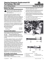
3-2. Duty Cycle And Overheating
Y Exceeding duty cycle can
damage unit and void
warranty.
Percent duty cycle = 1.7 times the
number of 1 second (1000ms)
loads/outputs per minute, without
overheating. The one second load
is the rated output.
If unit overheats, output stops. A
HLP 3 message (see Section 8-4)
is displayed, and cooling fan runs.
Wait fifteen minutes for unit to cool.
Reduce amperage or duty cycle be-
fore welding.
27% Duty Cycle
Overheating
0
15
A or V
OR
Reduce Duty Cycle
Minutes
sduty1 5/95 / SA-207 877
NUMBER OF STUDS IN ONE MINUTE
16
STUD SIZE
0.000
0.125
0.250
0.375
0.500
0.625
0.750
30 40 60

OM-216 244 Page 10
SECTION 4 − INSTALLATION - POWER SOURCE
4-1. Selecting a Location
loc_2 3/96 - Ref. ST-151 556 / 803 618-B
Y Special installation may be
required where gasoline or
volatile liquids are present −
see NEC Article 511 or CEC
Section 20.
1 Lifting Handles
Use handles to lift unit.
2 Hand Cart
Use cart or similar device to move
unit.
3 Rating Label
Use rating label to determine input
power needs.
4 Line Disconnect Device
Locate unit near correct input
power supply.
24 in
(610 mm)
17 in
(432 mm)
12-1/2 in
(318 mm)
Movement
1
1
2
Y Do not move or operate unit
where it could tip.
Location
4
3
Dimensions And Weight
18 in
(460 mm)
18 in
(460 mm)
73 lb (33.1 kg)

OM-216 244 Page 11
4-2. Electrical Service Guide
Y CAUTION: INCORRECT INPUT POWER can damage this welding power source. This welding pow-
er source requires a CONTINUOUS supply of 60 Hz (+10%) power at +10% of rated input voltage. Phase
to ground voltage shall not exceed +10% of rated input voltage. Do not use a generator with automatic
idle device (that idles engine when no load is sensed) to supply input power to this welding power
source.
Actual input voltage should not exceed ± 10% of indicated required input voltage. If
actual input voltage is outside of this range, output may not be available.
NOTE
60 Hz Three Phase
Input Voltage 480 575
Input Amperes At Rated Output 55 45
Max Recommended Standard Fuse Rating In Amperes
1
Time-Delay
2
Normal Operating
3
60 50
Min Input Conductor Size In AWG
4
10 10
Max Recommended Input Conductor Length In Feet (Meters)
175
(53)
274
(83)
Min Grounding Conductor Size In AWG
4
10 10
Reference: 2005 National Electrical Code (NEC) (including article 630)
1 Consult factory for circuit breaker applications.
2 “Time-Delay” fuses are UL class “RK5” .
3 “Normal Operating” (general purpose - no intentional delay) fuses are UL class “K5” (up to and including 60 amp), and UL class “H” ( 65 amp and
above).
4 Conductor data in this section specifies conductor size (excluding flexible cord or cable) between the panelboard and the equipment per NEC Table
310.16. If a flexible cord or cable is used, minimum conductor size may increase. See NEC Table 400.5(A) for flexible cord and cable requirements.
Notes

OM-216 244 Page 12
4-3. Weld Output Receptacles And Selecting Cable Sizes
Y ARC WELDING can cause Electromagnetic Interference.
To reduce possible interference, keep weld cables as short as possible, close together, and down low, such as on the floor.
Locate welding operation 100 meters from any sensitive electronic equipment. Be sure this welding machine is installed
and grounded according to this manual. If interference still occurs, the user must take extra measures such as moving
the welding machine, using shielded cables, using line filters, or shielding the work area.
40035030025020015010050
300
400
500
600
700
800
900
1000
1100
1200
1300
1400
1500
1600
1700
1800
1900
2100
2/0
4/0
2-4/0
Use multiple 4/0 cables or
500 mcm cable or larger.
No. 1
Cable Size
Area
1/4”
5/16”
3/8”
7/16”
1/2”
5/8”
3/4”
7/8”
1”
Arc Stud Size & Welding Current (Shank Size)
TOTAL CABLE LENGTH (FT)
(Ground And Electrode)
Output Receptacles
Weld Output
Terminals
Y Turn off power before connecting to
weld output terminals.
Y Do not use worn, damaged, undersized,
or poorly spliced cables.
(Work)
(Gun)
* This chart is a general guideline and may not suit all applications. If cable overheating occurs (normally you can smell it), use next size larger
cable.

OM-216 244 Page 13
4-4. Connecting 3-Phase Input Power
2/04 - Ref. 802 136-A
Y Installation must meet all National
and Local Codes − have only quali-
fied persons make this installation.
Y Disconnect and lockout/tagout in-
put power before connecting input
conductors from unit.
Y Always connect green or green/
yellow conductor to supply
grounding terminal first, and nev-
er to a line terminal.
. The Auto-Link circuitry in this unit au-
tomatically adapts the power source
to the primary voltage being applied.
Check input voltage available at site.
This unit can be connected to any in-
put power between 480 or 575 VAC
without removing cover to relink the
power source.
1 Input Power Cord.
2 Disconnect Device (switch shown in
the OFF position)
3 Green Or Green/Yellow Grounding
Conductor
4 Disconnect Device Grounding
Terminal
5 Input Conductors (L1, L2 And L3)
6 Disconnect Device Line Terminals
Connect green or green/yellow grounding
conductor to disconnect device grounding
terminal first.
Connect input conductors L1, L2, and L3
to disconnect device line terminals.
7 Overcurrent Protection
Select type and size of overcurrent protec-
tion using Section 4-2 (fused disconnect
switch shown).
Close and secure door on disconnect
device. Remove lockout/tagout device,
and place switch in the On position.
= GND/PE Earth Ground
L1
2
1
L2
L3
3
3
4
5
6
7
Tools Needed:
1

OM-216 244 Page 14
803 619-B
1 Circuit Breaker CB1
CB1 protects 60 volts ac portion
of Remote 4 pin receptacle from
overload.
Press button to reset breaker.
1
4-5. Circuit Breaker
4-6. 4 Pin Receptacle Information
4
CONTROL Socket Socket Information
3
4
GUN
CONTROL
1
2
Output to control of gun solenoid; 90 volts dc.
2
1
3
4
Contact closure between 3 and 4 initiates weld
cycle.
4-7. Rack Mounting
This unit is capable of being rack mounted (Contact your distributor).

OM-216 244 Page 15
SECTION 5 − INSTALLATION - STUD GUN
Y Disconnect gun from power
source before installing or
removing components.
1 Chuck
2 Chuck Adapter
To install chuck, align chuck in front
of chuck adapter. Tap firmly on the
end of chuck to seat chuck into
adapter. Not necessary to pound
on the end of the chuck. This will da-
mage the chuck.
. There is a unique chuck for ev-
ery diameter of stud. Rectan-
gular and other special shape
studs may require specialized
chucks. There is also a depth
stop inside of the chuck. The
depth stop should be adjusted
so that you are retaining a good
portion of the stud you are set-
ting up to weld. Typically, this is
one third to one half of the
length of the stud being welded.
1
5-1. Chuck Installation
2
Do not hammer or beat
chuck into position.
1 Chuck Key
2 Hole - Chuck Adapter
To remove chuck, insert short, ta-
pered end of chuck ejector key into
one of the holes in the side of the
chuck adapter. It may be necessary
to move the rubber bellows to see
the holes in the side of the chuck
adapter.
Rotate chuck key clockwise or
counter clockwise and the chuck
will pop out of the chuck adapter.
. Chuck is held into the chuck
adaptor with a #2 morse taper.
1
5-2. Chuck Removal
2

OM-216 244 Page 16
Foot Installation
1 Leg Screw
2 Leg Washer
3 Ferrule Grip
4 Foot
5 Leg
The foot is available in 3 different sizes
(small, medium, and large) and 2 different
configurations (closed and split). Typically, a
split foot is only used when welding headed
anchors and sheer connectors.
The foot is installed on the ends of the legs.
Unscrew the flat head screws from the ends
of the legs. Place the trim washers on the flat
head screws and place the screws through
the adjustment slots in the foot. Reattach the
screws to the legs.
Leg Installation
6 Flat Side of Leg
7 Leg Set Screw
Insert legs into leg retainers. Line up the flat
side of the legs with set screws Tighten set
screws securely.
4
5-3. Foot and Leg Setup
5
1
2
3
Foot Size Stud Range
Small
Medium
Up to 1/2 in.
5/8 to 3/4 in.
6
7
Make sure flat side of legs face
outside ot gun body to ensure
alignment with set screws.
Part #
219670
219671
1 Ferrule Grip
There are 3 set screws that retain the ferrule
grip or spark shield in the foot. Loosen all 3
set screws.
Push the ferrule grip or spark shield into the
foot. Press ferrule grip firmly into the foot so
it seats against the back stop. Line up the 2
side holes in the ferrule grip with set screws
in the foot. Tighten set screws securely.
. If a spark shield is being used, it is not
necessary to align the spark shield with
the set screws in the the foot.
5-4. Ferrule Grip / Spark Shield Removal and Installation
1

OM-216 244 Page 17
1 Leg Screw
2 Foot
3 Ferrule
4 Ferrule Grip
5 Stud
. Alignment of the foot is very important,
if the foot is not aligned properly it can
create bad welds in the form of hang−
ups.
Place a stud into the chuck and a ferrule into
the ferrule grip. The stud should sit perfectly
in the center of the ferrule. If not, loosen the
flat head screws on the legs holding the foot.
Position the foot so the stud is perfectly
aligned in the ferrule. Retighten the flat head
screws.
5-5. Foot Alignment
1
5
2
3
4
5-6. Connecting Stud Gun and Work Clamp to Power Source
1
2
3
4
Perform the following procedures when
connecting stud gun to power source:
• Connect weld cable
• Connect control cable
. Use the same instructions provided if
connecting to an extension cable.
Connecting Weld Cable and Work
Ground Cable
1 Flat
2 Keyway
To connect to receptacle, align keyway, in-
sert connector, and turn clockwise (approx-
imately 1/2 turn).
Connect stud gun to black output terminal
labeled gun.
Connect work cable to black output terminal
labeled work.
Connecting Control Cable
3 Key
4 Keyway
Align key in end of control cable with key
way inside connector on front of power sup-
ply. Push the connectors together. Turn re-
taining nut on control cable clockwise.
When nut is snug the connection is com-
plete.
To remove, unscrew connector counter
clockwise.
Ref 802 385-A

OM-216 244 Page 18
Plunge Settings When Using Ferrules
Plunge controls the amount of stud that is
melted during the arc time. Too much plunge
and the fillet will overfill the ferrule or create
excessive splatter when using a spark
shield. Too little plunge and there may be in-
complete fillet formation. There should be
approximately 1/8 of an inch of stud protrud-
ing past the end of the ferrule. A bit less for
smaller studs, a bit more for larger studs.
1 Set Screw
2 Plunge Depth
To adjust plunge, loosen leg set screws on
gun body. Move foot towards gun or away
from gun to increase or decrease plunge.
Plunge measurements are from end of stud
and do not include the flux load.
. These instructions are for standard fer-
rules. For reduced fillet ferrules (only
recommended for very specific applica-
tions) decrease the amount of plunge by
half.
Plunge Settings For Short Arc or Gas Arc
Stud Welding
For Short Arc or Gas Short Arc the stud
should protrude past the end of the spark
shield by about 0.04 in (1 mm). This is about
the same as the flange thickness on flanged
style studs. For standard time duration Gas
Short Arc the plunge should be set at about
2 flange thicknesses or 0.08 in (2 mm).
5-7. Plunge Adjustment
1
PlungeStud Diameter
.25 - .625
.75 and up
.125
.188
2
0 - .25 .094
Notes

OM-216 244 Page 19
The lift controls the arc length and is a factor
in controlling the heat of the welding process.
Lift should be set at 3/32 or .094 in (2.5 mm).
Measuring LIft
Y For safety from accidental activation,
always disconnect the weld cable
from the power source before making
any stud gun adjustments or per-
forming any service on the stud gun.
1 Stud Lift Measurement
To measure stud lift, hold a scale against
some fixed part of the tool. The front cover or
foot will work well. Press the trigger so the
tool activates the lift mechanism. Now mea-
sure again. The lift is the difference between
the two measurements.
Adjusting Lift
2 Location of Core Set Screws
To adjust lift, remove the slotted screw hold-
ing the rear cap in place. Remove rear cap.
Loosen the nylon tipped set screw that holds
the adjustable core in place. To increase lift,
turn the adjustable core screw counter
clockwise. To decrease lift, turn the adjust-
able core screw clockwise. Each half turn
equals .025 in (0.6 mm).
Once lift is set, retighten nylon tipped set
screw to keep the adjustable core in place.
Install rear cap and tighten cap screw.
. Keep cap in place to prevent dirt from en-
tering the stud gun mechanism
5-8. Adjusting Stud Lift
2
1/16 in (1.6 mm) lift for studs up to 5/16 (7.9 mm) diameter
3/32 in (2.4 mm) lift for studs over 5/16 (7.9 mm) to 1/2 in (13 mm) diameter
1/8 in (3.2 mm) lift for studs over 1/2 (13 mm) diameter
LIft Adjustment Table
2
1

OM-216 244 Page 20
SECTION 6 − OPERATION - POWER SOURCE
AmperageTime (ms)
POWER
SELECT
ADJUST
OUTPUT ON
READY
WORK
STUD GUN
CONTROL
6-1. Front Panel Controls
232 187-A
1
1 Power Switch
Use switch to turn unit On/Off.
2 Time Indicator Meter
3 Amperage Indicator Meter
4 Stud Count Indicator Light
5 READY to Weld Indicator Light
6 OUTPUT ON Indicator LIght
7 Time/Amperage Control
(see Section 6-2)
8 Gas Valve (Optional)
9 Time/Amperage Select Button
10 Stud Count Key Reset (Optional)
5
3
10
2
6
7
STUD COUNT
4
OPTIONAL
OPTIONAL
COUNT
RESET
GAS OUT
9
8
/