Page is loading ...

WS-7220U-IT
915 MHz
Wireless Weather Station
Instruction Manual
Contents
Language Page
Englis
h 2
French 24
Spanis
h 48
TABLE OF CONTENTS
Topic Page
Introductio
n 3
Inventory of Contents 4
Qui
ck Set Up 4
Detailed Set Up 6
Batte
ry Installation 6
12 or 24 Hour
Time Display 8
Time Settin
g 9
Features 10
Mini
mum & Maximum Temperature
and Humidity 10
Resetting Mini
mum & Maximum
Temperature and Humidity 10
Adding Additional
Thermo-Hygro
Sensor
s 11
Viewing & Operating with Multiple
The
rmo-Hygro Sensors 13
Mountin
g 13
Troubleshooting 17
Maintenance & Care Inst
ructions 18
Spe
cifications 18
Warranty Information 19
I N S T A N T
TRANSMISSIO
N
is the state-of-the-
art new wireless
transmission technology, exclusive ly
designed
and developed by LA CROSSE
TECHNOLOG
Y.
INSTANT TRANSMISSION
offers you can an immediate update (every 4
seconds!)
of all your outdoor data measured
from
the transmitters: follow your climatic
variations in real-time!
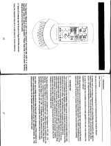
Outdoor
Temperature
(˚F or ˚C)
Indoor
Temperature
(˚F or ˚C)
Connection w
/
Sensor
Icon
Low Battery
Indicator
12 or 24 Hour
Time
Display
Outdoor
Hu
midity
(%RH)
Minimum/
Maximum &
Plus
Button
This product offers:
Figure 1
Set/Channel
Button
Figure 2
Mounting
Bracket
Wireless
Thermo-hygro
Sensor
TX29UD-TH-IT
INVENTORY OF CONTENTS
1. Wireless Weather Station (Figure 1)
2. Wireless Thermo-Hygro Sensor (TX29UD-TH-
IT)
and mounting bracket. (Figure 2)
3. 3 each, 1/2" Philips screws.
4. One strip of double sided adhesive tape.
5. Instruction Manual and Warranty Card.
ADDITIONAL EQUIPMENT
(not in
cluded)
1. 1 Philips screwdriver.
2. 2 Fresh “AA” 1.5V Alkaline Batteries.
3. 2 Fresh “AAA” 1.5V Alkaline Batteries.
QUICK SETUP
Hint:
Use good quality Alkaline Batteries; avoid
rechargea
ble batteries.
1. Have the Wireless Weather Station and
the
rmo-hygro sensor 3 to 5 feet apart.
2. Batteries should be out of both units for 10
mi
nutes.
3. Place the batteries into the thermo-hygro
sensor
first and next into the Wireless
Weather Station.
4. DO NOT PRESS ANY BUTTONS FOR 15
MINUTES.
In
this time the Wireless Weather Station and
th e
ther m o-hygro senso r will begin to
com
municate with each other, and the display
will
show both the indoor temperature and an
outdoor temperature. If the Wireless Weather
Station
does not display both temperatures after
the
15 minutes, please retry the set up as stated
ab
ove. After both indoor and outdoor
tempe
ratures are displayed for 15 minutes you
can
place your thermo-hygro sensor outdoors,
and
set your time.
The
thermo-hygro sensor should be placed in a
dry, shaded area (ex: under the eve of a roof).
The
thermo-hygro sensor has a range of 330
feet. Any walls that the signal will have to pass
through
will reduce distance. An outdoor wall
or
window will have up to 20 feet of resistance
and
an interior wall will have up to 10 feet of
resistanc
e. Your distance plus resistance should
not
exceed 330 feet in a straight line.
NOTE:
Fog and mist will not harm your thermo-
GB
P.2
FCC ID: OMOTX29UTH (transmitter)
RF Exposure mobile:
The
internal / external antennas used for this mobile transmitter
must provide a separation distance of at least 20 cm (8 inches)
from
all persons and must not be co-located or operating in
conjunction with any other antenna or transmitter.”
Statement acco
rding to FCC part 15.19:
This
device complies with Part 15 of the FCC Rules. Operation
is
subject to the following two conditions: (1) this device may
not
cause harmful interference, and (2) this device must accept
any interference received, including interference that may
cause undesired ope
ration.
Statement acco
rding to FCC part 15.21:
Modifications
not expressly approved by this company could
void the user’s authority to operate the equipment.
Statement acco
rding to FCC part 15.105:
NOTE: This equipment has been tested and found to comply
with
the limits for a Class B digital device, pursuant to Part 15
of
the FCC Rules. These limits are designed to provide
re
asonable protection against harmful interference in a
residential
installation. This equipment generates, uses and
can
radiate radio frequency energy and, if not installed and
used
in accordance with the instructions, may cause harmful
inter
ference to radio communications.
However, there is no guarantee that interference will not occur
in
a particular installation. If this equipment does cause harmful
inter
ference to radio or television reception, which can be
dete
rmined by turning the equipment off and on, the user is
encou
raged to try to correct the interference by one or more
of the
following measures:
• Reorient or relocate the receiving antenna.
• Increase the separation between the equipment and
recei
ver.
• Connect the equipment into an outlet on a circuit different
from that to which the recei
ver is connected.
Consult
the dealer or an experienced radio/TV technician for
help
GB
P.3
GB
P.4
GB
P.5

hygro sensor, but direct rain must be avoided.
DETAILED SETUP GUIDE
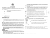
I. BATTERY INSTALLATION (When one
thermo-hygro sensor is being used)
1. First, insert the batteries to the thermo-hygro
sensor (see “A. thermo-hygro sensor”
below).
2. Within 2 minutes of powering up the sensor,
insert the batteries to the Wireless Weather
Station (see “B. Wireless Weather Station”
below). Once the batteries are in place, all
segments of the LCD will light up briefly.
Following the indoor temperature and the
time as 12:00 will be displayed. If they are
not shown in LCD after 60 seconds, remove
the batteries and wait for at least 60 seconds
before reinserting them. Once the indoor
data is displayed user may proceed to the
next step.
3. After the batteries are inserted, the Weather
Station will start receiving data signal from
the sensor. The outdoor temperature and
humidity should then be displayed on the
Weather Station. If this does not happen after
2 minutes, the batteries will need to be
removed from both units and reset from step
1 and the signal reception icon is no longer
shown.
SIZE AA LR6
SIZE AA LR6
Battery
Compartment
Battery Cover
A. THERMO-HYGRO SENSOR
1. Remove the Battery Cover.
2. Observing the correct polarity, install 2 “AA”
Alkaline Batteries-make sure they do not
spring free, or start-up problems may occur.
Replace the Battery Cover.
B. WIRELESS WEATHER STATION
Note:
After the batteries are installed, DO NOT
press any buttons. This may interfere with the
signals, causing temperatures to register
incorrectly.
1. Remove the Battery Cover on the back of
the Wireless Weather Station.
2. Observing the correct polarity, install 2 “AAA”
Alkaline Batteries.
3. Replace Battery Cover.
4. Wait 15 minutes before pressing any buttons.
* When the signal is successfully received by
the Weather Station, the icon will be switched
on. (If not successful, the icon will not be
shown in LCD) So the user can easily see
whether the last reception was successful
(icon on) or not (icon off). On the other hand,
the short blinking of the icon shows that a
reception is being done now.
• If the signal reception is not successful on
the first frequency (915MHz) for 45 seconds,
the frequency is changed to 920MHz and
the learning is tried another 45 seconds. If
still not successful the reception is tried for
Battery
Compartment
Battery Cover
Sensor signal
reception icon*
45 seconds on 910MHz. This will also be
done for re-synchronization.
C. SELECTING 12 OR 24 HOUR TIME
DISPLAY
1. Press and hold the SET/CH button for about
5 seconds.
2. “12h” will begin to flash in the TIME section
of the LCD
3. Press the MIN/MAX/+ button to toggle
between “12h” and “24h” time.
Note:
• Selecting 12 hour time will automatically
select ˚F as your temperature unit.
• Selecting 24 hour time will automatically
select ˚C as your temperature unit.
4. Press and release the SET/CH button again
to enter Time Setting.
D. TIME SETTING
1. After exiting the 12/24 Hour Setting, the hour
will begin flashing in the time display.
2. Press and release the MIN/MAX/+ button to
select the desired hour.
Note:
PM will appear to the left of the time
display for PM hours. For AM hours, that
area will remain blank.
3. Press and release the SET/CH button again,
and the minutes will begin to flash.
4. Press and release the MIN/MAX/+ button to
select the desired minutes.
5. Press and release the SET/CH button to exit
the SET UP mode.
Note:
If no buttons are pressed for 10
seconds, the Wireless Weather Station will
automatically return to the normal display.
II. FEATURES
A. MINIMUM AND MAXIMUM
TEMPERATURES AND HUMIDITY
1. Press and release the MIN/MAX button,
“MIN” appears at the bottom of the LCD and
the recorded minimum temperatures and
humidity are displayed.
2. Press and release the MIN/MAX button
again to view maximum recorded
temperatures and humidity. “MAX” appears
at the bottom of the LCD and the maximum
temperatures and humidity are displayed.
3. Press and release the MIN/MAX button once
more to return to the current temperatures
and humidity.
B. RESETTING THE MINIMUM AND
MAXIMUM TEMPERATURES AND
HUMIDITY
To reset both the minimum and maximum
temperatures and humidity-press and hold the
MIN/MAX button for 5 seconds.
C. ADDING ADDITIONAL REMOTE
SENSORS (OPTIONAL)
The WS-7220U-IT is able to receive signals from
2 additional thermo-hygro sensors. The following
are instructions for the set-up of thermo-hygro
sensor units with the WS-7220U-IT. These extra
sensors can be purchased through the same
dealer as this unit.
1. Remove all the batteries from the receiver
and sensor(s) and wait 60 seconds. During
these 60 seconds, press any button 20 times
to discharge any excess power.
2. Insert the batteries to the first thermo-hygro
sensor.
3. Within 2 minutes of powering up the first
sensor, insert the batteries to the Weather
Station. Once the batteries are in place, all
segments of the LCD will light up briefly.
Following the indoor temperature and the
time as 12:00 will be displayed. If they are
not shown in LCD after 60 seconds, remove
the batteries and wait for at least 60 seconds
before reinserting them.
4. The outdoor temperature and humidity from
the first sensor (channel 1) should then be
displayed on the Weather Station. If this does
not happen and the signal reception icon is
not shown, after 2 minutes, the batteries will
need to be removed from both units and
reset from step 1.
5. Insert the batteries to the second sensor as
soon as the outdoor temperature and
humidity readings from the first sensor are
displayed on the Weather Station.
NOTE:
You must insert the batteries into
the second sensor within 30 seconds of
reception of the first sensor.
6. The outdoor temperature and humidity from
the second sensor and the “channel 2” icon
should then be displayed on the Weather
Station. If this does not happen after 2
minute, the batteries will need to be removed
from all the units and reset from step 1.
7. Insert the batteries to the third sensor as
soon as the “channel 2” icon and outdoor
data are displayed on the Weather Station.
Then within 2 minutes, the channel 3 outdoor
data from the third sensor will be displayed
and the channel icon will shift back to “1”
once the third transmitter is successfully
received. If this is not happen, user shall
restart the setting up from step 1.
NOTE:
You must insert the batteries into
the third sensor within 30 seconds of
reception of the second sensor.
IMPORTANT:
Tr ansmission problems will arise
if the setting for multiple sensors is not followed
as described above. Should transmission
problems occur, it is necessary to remove the
batteries from all units and start again the set-
up from step 1.
D. VIEWING AND OPERATING WITH
MULTIPLE REMOTE SENSOR UNITS
1. To view the temperature of a different thermo-
hygro sensor unit, press and release the SET/
CH button. A shift from one “boxed” number
to the next should be observed on the right
side of the OUTDOOR LCD.
2. To view the Minimum/Maximum temperature
& humidity: first select from which thermo-
hygro sensor to read data (indicated by the
“boxed” number). Pressing and releasing the
MIN/MAX button will toggle through the
minimum and maximum indoor temperature,
and the minimum and maximum outdoor
temperature and humidity.
3. To reset the Minimum/Maximum readings,
press and hold the MIN/MAX button for 5
seconds.
III. MOUNTING
Note:
To achieve a true temperature reading,
avoid mounting in direct sunlight. We recommend
that you mount the thermo-hygro sensor on an
outside North-facing wall (under the eve of a
house is ideal). The sending range is 330 feet;
obstacles such as walls, stucco walls, concrete,
and large metal objects will reduce the range.
Place the Wireless Weather Station and thermo-
hygro sensor in their desired locations before
permanently mounting.
GB
P.6
GB
P.7
GB
P.8
GB
P.9
GB
P.10
GB
P.11
GB
P.12
GB
P.13

A. THERMO-HYGRO SENSOR
The thermo-hygro sensor can be mounted in
two ways:
• with the use of screws, or
• using the adhesive tape.
A. MOUNTING WITH SCREWS
1. Remove the mounting bracket from the
remote thermo-hygro sensor.
2. Place the mounting bracket over the desired
location.
3. Through the three screw holes of the bracket,
mark the mounting surface with a pencil.
4. Screw mounting bracket onto the mounting
surface. Ensure that the screws are flush
with the bracket.
5. Insert the thermo-hygro sensor into the
bracket.
B. MOUNTING WITH ADHESIVE TAPE
Note:
The adhesive tape is not intended to be
used as a permanent mounting solution. Only
use the adhesive tape while you are positioning
the Weather Station and thermo-hygro sensor.
1. With a nonabrasive solution, clean and dry
the back of the mounting bracket and the
mounting surface to ensure a secure hold.
The mounting surface should be smooth and
flat.
2. Remove the protective strip from one side
of the tape.
3. Adhere the tape to the designated area on
the back of the mounting bracket.
4. Remove the protective strip from the other
side of the tape.
5. Position the remote thermo-hygro sensor in
the desired location, ensuring that the
Weather Station can receive the signal.
Note:
Mounting with adhesive tape is not
recommended as a permanent mounting
solution. Only use the adhesive tape during
set-up process
B. WIRELESS WEATHER STATION
1. The Wireless Weather Station comes with
the table stand attached to the back of the
Receiver. If you wish to use the table-stand,
simply place the Wireless Weather Station
in an appropriate location, and pull out on
the attached stand.
2. To wall mount, push the table stand flat
against the Wireless Weather Station (if it
isn’t already flat). Fix a screw (not included)
into the desired wall, and place the Wireless
Weather Station onto the screw using the
hanging hole on the backside. Gently pull
the Wireless Weather Station down to lock
the screw into place.
TROUBLESHOOTING
NOTE:
For problems not solved, please contact
La Crosse Technology via e-mail or phone, or
visit our website, www.lacrossetechnology.com
Problem: The LCD is faint
Solution: Replace batteries
Problem: No outdoor temperature is displayed.
Solution:
1. Bring any units from outside, inside and
place the units 3 to 5 feet apart with nothing
in-between them.
2. Remove the batteries from all units.
3. Press one of the buttons on the Wireless
Weather Station display at least 20 times to
clear all memory. Verify that the display is
blank before proceeding.
4. Using good quality alkaline batteries, place
the batteries back into the outdoor
temperature sensor; making sure they are
installed according to the diagrams in the
battery compartment.
5. Taking care not to press any buttons, reinstall
the batteries in the Wireless Weather Station
according to the diagram in the battery
compartment.
6. Do not press any buttons for at least 15
minutes after installing the batteries. (This
is to let the units establish a good
connection.)
7. During the course of the 15 minutes an
outdoor temperature should appear on the
display. You can now put your sensor(s) back
outside.
MAINTENANCE AND CARE
INSTRUCTIONS
• Extreme temperatures, vibration, and shock
should be avoided to prevent damage to the
units.
• Clean displays and units with a soft, damp
cloth. Do not use solvents or scouring
agents; they may mark the displays and
casings.
• Do not submerge in water.
• Do not subject the units to unnecessary heat
or cold by placing them in the oven or freezer.
• Opening the casings invalidates the
warranty. Do not try to repair the unit.
Contact La Crosse Technology for repairs.
SPECIFICATIONS
Transmitting Frequency 915 MHz
TEMPERATURE MEASURING RANGES
Indoor 14.1˚F to 139.8˚F with
0.2˚F resolution.
Outdoor -39.8˚F to 139.8˚F with
0.2˚F resolution.
HUMIDITY MEASURING RANGE
Outdoor (%RH) 1% to 99%
Transmitting range Maximum 330 feet
(100m) open space
TEMPERATURE CHECKING INTERVAL
Indoor Every 15 seconds
Outdoor Every 4 seconds
BATTERIES-(Alkaline recommended)
Thermo-Hygro Sensor 2 x AA, 1.5V
Wireless Weather Station 2 x AAA, 1.5V
DIMENSION: (H x W x D)
Wireless Weather Station 5.90" x 2.36" x 0.81"
(150 x 60 x 20.7mm)
Thermo-Hygro Sensor 5.05" x 1.5" x 0.83"
(128.3 x 38.2 x 21.2mm)
Battery life Up to 24 Months
WARRANTY INFORMATION
La Crosse Technology, Ltd provides a 1-year
limited warranty on this product against
manufacturing defects in materials and
workmanship.
This limited warranty begins on the original date
of purchase, is valid only on products purchased
and used in North America and only to the
original purchaser of this product. To receive
warranty service, the purchaser must contact
La Crosse Technology, Ltd for problem
determination and service procedures.
Warranty service can only be performed by a
La Crosse Technology, Ltd authorized service
center. The original dated bill of sale must be
presented upon request as proof of purchase
to La Crosse Technology, Ltd or La Crosse
Technology, Ltd’s authorized service center.
La Crosse Technology, Ltd will repair or replace
this product, at our option and at no charge as
stipulated herein, with new or reconditioned
parts or products if found to be defective during
the limited warranty period specified above. All
replaced parts and products become the
property of La Crosse Technology, Ltd and must
be returned to La Crosse Technology, Ltd.
Replacement parts and products assume the
remaining original warranty, or ninety (90) days,
whichever is longer. La Crosse Technology, Ltd
will pay all expenses for labor and materials for
all repairs covered by this warranty. If necessary
repairs are not covered by this warranty, or if a
product is examined which is not in need or
repair, you will be charged for the repairs or
examination. The owner must pay any shipping
charges incurred in getting your La Crosse
Technology, Ltd product to a La Crosse
Technology, Ltd authorized service center. La
Crosse Technology, Ltd will pay ground return
shipping charges to the owner of the product to
a USA address only.
Your La Crosse Technology, Ltd warranty covers
all defects in material and workmanship with the
following specified exceptions: (1) damage
caused by accident, unreasonable use or
neglect (including the lack of reasonable and
necessary maintenance); (2) damage occurring
during shipment (claims must be presented to
the carrier); (3) damage to, or deterioration of,
any accessory or decorative surface; (4)
damage resulting from failure to follow
instructions contained in your owner’s manual;
(5) damage resulting from the performance of
repairs or alterations by someone other than an
authorized La Crosse Technology, Ltd
authorized service center; (6) units used for
other than home use (7) applications and uses
that this product was not intended or (8) the
products inability to receive a signal due to any
source of interference.. This warranty covers
only actual defects within the product itself, and
does not cover the cost of installation or removal
from a fixed installation, normal set-up or
adjustments, claims based on misrepresentation
by the seller or performance variations resulting
from installation-related circumstances.
LA CROSSE TECHNOLOGY, LTD WILL NOT
ASSUME LIABILITY FOR INCIDENTAL,
CONSEQUENTIAL, PUNITIVE, OR OTHER
SIMILAR DAMAGES ASSOCIATED WITH THE
OPERATION OR MALFUNCTION OF THIS
PRODUCT. THIS PRODUCT IS NOT TO BE
USED FOR MEDICAL PURPOSES OR FOR
PUBLIC INFORMATION. THIS PRODUCT IS
NOT A TOY. KEEP OUT OF CHILDREN’S
REACH.
GB
P.14
GB
P.15
GB
P.16
GB
P.17
GB
P.18
GB
P.19
GB
P.20
GB
P.21
/