Bay Networks 00BASE-FX User manual
- Category
- Network switches
- Type
- User manual
This manual is also suitable for

Part No. 893-00994-A
May 1997
Reference for the
Centillion 100
8/2-port EtherSpeed
10BASE-T/100BASE-FX
Switch Module
893-00994-A Page 1 Tuesday, April 29, 1997 5:55 PM

2
Introduction
The Centillion 100 EtherSpeed 10BASE-T/100BASE-FX Switch Module from Bay Networks
®
inserts
into one slot of a Centillion 100
™
chassis. The module provides eight 10BASE-T switched ports that
operate at 10 megabits per second (Mb/s) and two 100BASE-FX switched ports that operate at
100 Mb/s.
This guide contains information specific to the 8/2-port EtherSpeed 10BASE-T/100BASE-FX Switch
Module and includes the following topics:
• Status LED descriptions
• Default configuration
• 100BASE-FX cable requirements
• 10BASE-T port pin assignments
• Technical specifications
• Declaration of Conformity
For information about installing and troubleshooting Centillion 100 EtherSpeed
™
modules, refer to
Using the Centillion 100 EtherSpeed Switch Modules
(Bay Networks part number 893-890-B). Refer
to
Using SpeedView 2.1 for Windows
(Bay Networks part number 893-891-B) for information about
how to use SpeedView
™
to configure features on an EtherSpeed module and a Centillion 100 switch.
Figure
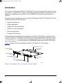
1 illustrates the 8/2-port EtherSpeed 10BASE-T/100BASE-FX Switch Module.
Figure 1. EtherSpeed 10BASE-T/100BASE-FX Switch Module
937FA
Inserter/extractor
levers
Captive retaining
screws
LEDs
Backplane connector
Power supply
connector
Printed circuit
board
Eight 10BASE-T ports
(RJ-45)
Two 100BASE-FX ports
(SC connectors)
893-00994-A Page 2 Tuesday, April 29, 1997 5:55 PM

3
Status LEDs
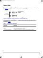
Two banks of status LEDs on the EtherSpeed module correspond to the port numbers on the module
(see Figure
2). Each fiber port has a correspondingly numbered LED.
Figure 2. EtherSpeed 10BASE-T/100BASE-FX Switch Module LEDs
Each numbered LED turns on, turns off, or blinks to indicate link status and/or data activity as
described in T
able 1.
Table 1. EtherSpeed LED definitions
LED State Meaning
Turns on Port is enabled from network management, and a cable is attached.
Blinks Data is being transmitted or received.
On (steady, not blinking) Port detects link pulses from the other end, but there is no data.
1 2 3 4
5 6 7 8
9
100 Mb/s
fiber port LEDs
10
938EA
ETHER
S
PEED
10/100
893-00994-A Page 3 Tuesday, April 29, 1997 5:55 PM

4
Default Configuration
T
able 2 lists the factory defaults for ports on the EtherSpeed module.
Table 2. Factory defaults for EtherSpeed 10/100 Mb/s ports
Parameter Factory default Configurable options
Switching mode Transparent Transparent
Spanning Tree Protocol None None, IEEE
Path cost 16 1–65535
Port partition state Enabled Enabled, Disabled
Filters Disabled Enabled, Disabled
PMD type • 10BASE-TX
• 100BASE-FX
None
Port speed
• 10BASE-TX
• 100BASE-FX
10 Mb/s
100 Mb/s (autosensing)
None
None
Half/full duplex Full Duplex Half/full duplex
Bridge group 2 2–32
Priority 128 0-255
6539
TX RX
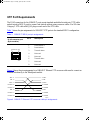
Fiber Port Requirements
Two SC fiber optic connectors (see Figure
3) on the
EtherSpeed module provide 100BASE-FX
100 Mb/s ports. The 100BASE-FX ports have the
following options and requirements:
• Cable Options
— 62.5-micron multimode fiber optic
— 50/125-micron multimode fiber optic
• Maximum fiber cable length
— 380 meters (1246.4 feet) when operating in
half-duplex mode
— 128 meters (419.84 feet) if one of the FX
ports is connected to a repeater that has FX
ports and TX ports
Figure 3. SC connector
893-00994-A Page 4 Tuesday, April 29, 1997 5:55 PM

5
UTP Port Requirements
The RJ-45 connectors for the 10BASE-T ports accept standard unshielded twisted pair (UTP) cable
and are wired as MDI-X ports to connect end stations without using crossover cables. Use 100-ohm
Category 5 UTP cable with RJ-45 plugs on each end of the UTP cable.
T
able 3 shows the pin assignments for 10BASE-T UTP ports in the standard MDI-X configuration.
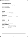
Figure
4 shows the pin assignments for a 10BASE-T Ethernet UTP crossover cable used to connect an
Ethernet hub directly to the EtherSpeed module.
Figure 4. 10BASE-T Ethernet UTP crossover cable pin assignments
Table 3. 10BASE-T MDI-X port pin assignments
RJ-45 connector port
(8-pin modular)
Pin # MDI-X ports
1 Receive data +
2 Receive data –
3 Transmit data+
4 Not used
5 Not used
6 Transmit data –
7 Not used
8 Not used
4026
1 2 3 4 5 6 7 8
1
2
3
4
5
6
7
8
1
2
3
4
5
6
7
8
TD+
TD-
RD+
Unused
Unused
RD-
Unused
Unused
TD+
TD-
RD+
Unused
Unused
RD-
Unused
Unused
6740.1
893-00994-A Page 5 Tuesday, April 29, 1997 5:55 PM

6
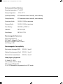
Technical Specifications
Network Protocol and Standards Compatibility
IEEE 802.3 for 10 Mb/s ports
IEEE 802.3u for 100 Mb/s ports
Data Rate
100 Mb/s
Interfaces
SC fiber optic connectors for 100BASE-FX Ethernet
RJ-45 (8-pin modular) connectors for 10BASE-T Ethernet
Microprocessors
Baseboard: 64-bit MIPS 4700 series processor, 133 MHz
Memory
Processor: 2 MB
Buffer pool: 4 MB
Electrical Specifications
Power consumption: 35 W (119.35 BTUs)
Physical Specifications
Dimensions: (L) 10.5 by (W) 12.5 by (H) 1.0 in.
(L) 26.7 by (W) 31.7 by (H) 2.5 cm
Weight: 2.5 lbs (1.1 kg)
893-00994-A Page 6 Tuesday, April 29, 1997 5:55 PM

7
Environmental Specifications
Operating temperature: 0
°
to 40
°
C
Storage temperature: –25
°
to 70
°
C
Operating humidity: 85% maximum relative humidity, noncondensing
Storage humidity: 95% maximum relative humidity, noncondensing
Operating altitude: 10,000 ft (3,000 m) maximum
Storage altitude: 10,000 ft (3,000 m) maximum
Free fall/drop: ISO 4180-s, NSTA 1A
Vibration: IEC 68-2-6/34
Shock/bump: IEC 68-2-27-29
Electromagnetic Emissions
Meets requirements of:
FCC Part 15, Subpart B, Class A
EN 55 022 (CISPR 22:1985), Class A
VCCI Class 1 ITE
Electromagnetic Susceptibility
Electrostatic discharge (ESD): EC 801-2, Level 2
Radiated electromagnetic field: EC 801-3, Level 2
Electrical fast transient/burst: EC 801-4, Level 2
Safety Agency Approvals
UL listed (UL 1950)
CSA certified (CSA 22.2 #950)
TUV licensed (EN 60 950)
UL-94-V1 flammability requirements for all PC boards
893-00994-A Page 7 Tuesday, April 29, 1997 5:55 PM

8
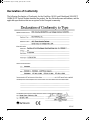
Declaration of Conformity
The following Declaration of Conformity for the Centillion 100 8/2-port EtherSpeed 10BASE-T/
100BASE-FX Switch Module identifies the product, the Bay Networks name and address, and the
applicable specifications that are recognized in the European community.
893-00994-A Page 8 Tuesday, April 29, 1997 5:55 PM

© 1997 by Bay Networks, Inc. All rights reserved.
Trademarks
Bay Networks is a registered trademark of Bay Networks, Inc. Centillion 100, EtherSpeed, and SpeedView are trademarks
of Bay Networks, Inc.
Other brand and product names are registered trademarks or trademarks of their respective holders.
Statement of Conditions
In the interest of improving internal design, operational function, and/or reliability, Bay Networks, Inc. reserves the right to
make changes to the products described in this document without notice.
Bay Networks, Inc. does not assume any liability that may occur due to the use or application of the product(s) or circuit
layout(s) described herein.
893-00994-A Page 9 Tuesday, April 29, 1997 5:55 PM
-
 1
1
-
 2
2
-
 3
3
-
 4
4
-
 5
5
-
 6
6
-
 7
7
-
 8
8
-
 9
9


Bay Networks 00BASE-FX User manual
- Category
- Network switches
- Type
- User manual
- This manual is also suitable for
Ask a question and I''ll find the answer in the document
Finding information in a document is now easier with AI
Related papers
-
Nortel Networks Centillion 100 User manual
-
-
Bay Networks TokenSpeed User manual
-
-
-
-
 Bay Technical Associates BayStack 304 User manual
-
-
-

Other documents
-
Trendnet TE100-SFXM Owner's manual
-
-
Avaya 2216T User manual
-
 Bay Technical Associates 350 User manual
-
 CBM America DT-4180 User manual
-
-
-
-
Nortel BayStack 450-12F Using Manual
-

