Page is loading ...

}
(ver.1.0 2017/8)
- 1 -
8 N.m
bicycle storage stand
BikeTower20D
instructions manual
Thank you for choosing the Minoura
BikeTower 20D
.
BikeTower is a very convenient and easy to set up bike
storage stand that can be installed in any room where the
ceiling height is between 2.1 and 2.7 meters high.
BikeTower comes with two bike cradles, and it can be
expanded up to 4 bikes and other items by installing
optional bike cradles and attachments.
Read this instructions manual carefully before use for
your safety, and keep on hand for future reference.
Part Name
Upper Pillar
(45mm diameter)
Bike Cradle
Cradle Arm
(Right and Left)
Cradle Hook
Clamp
Top Rubber Cup
(with spring inside)
Red Caution Indicator
Pillar Joint
Lower Pillar
(45mm diameter)
Bottom Rubber Cup
(without spring inside)
Center Pillar
(40mm diameter)
[Pillar Joint]
Pillar Joint
(Plastic)
Metal Ring
Cap Bolt M6x15
Lock Plate
Cap Bolt M6x15 (Do not loosen)
Cap Bolt M6x20
8 N.m
8 N.m
Recommended Tightening Torque = 8 N.m
Important Notes
•
Use the supplied plastic tie to hold the pillar to the ceiling
or the wall to avoid the stand from toppling over if the pillar
length was shortened if there was an issue with the locking
bolt.
Minoura is not responsible to any trouble if you don't use
this plastic tie correctly.
• For standard 2-wheel bike only. Not for use with
tandems or long wheel base bicycles.
• Each bike cradle is rated to hold up to 25 kgs.
If mounting heavy bikes, check the bolts often to make
sure they are not loose.
•
Check to make sure the Pillar Joint has remained secure by
pulling down the Upper Pillar after tightening the Pillar Joint
Bolt and the Lock Plate Bolt.
If the pillar has moved after tightening, discontinue using
and contact your dealer or Minoura directly. You may need to
replace the metal ring of the Pillar Joint.
• The pillar is supported by the internal spring applying
pressure to the ceiling.
Make sure that the pillar comes in contact with a stud
or other reinforced area of the ceiling otherwise the
pressure may cause a break through on dry wall or
other non-supportive material.
•
Adjust the pillar length correctly. If the red plastic appears
beneath the Upper Rubber Cup, it means the pillar is not
adjusted properly (too short).
•
Do not install the pillar upside down.
NEVER use BikeTower horizontally. It is for vertical use
ONLY.
•
The pillar must be completely vertical, and not at any angle.
Failure to do so will cause the stand to fall.
•
The rubber cap material may leave a mark on some ceilings
or oors.
We recommend placing a small piece of fabric or paper
between the rubber cup and the ceiling. Do not use a slippery
material.
• The coating on the cradle hook may leave a mark on
your bicycle frame, especially in light colors.
We recommend wrapping a piece of bar tape on the
hook where it comes in contact with the frame.
• Depending on the bike size, you may have to change the
clamp position from the fatter Upper or Lower Pillar to the
narrower Center Pillar.
In this case, install the supplied plastic shim between the
clamp and the pillar.
•
The pillar is just a single pole so it's easy to turn. Do not place
any fragile items or sharp edge articles around the pillar.
• This product is subject to change without prior notice
for quality and safety improvements.

- 2 -
How To Setup
Measurement
→
Temporally Setting
→
Adjusting Length
→
Setting
→
Check
→
Fix
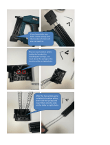
1
2 3 4
○
×
}
}
Loosen
Loosen
The Upper
and Lower
Pillars come
separated.
The Center
Pillar is
retraced inside
the Upper
Pillar.
Loosen the
M6x15 bolt
and two M6x20
bolts of the
upper Pillar
Joint to extract
the Center
Pillar.
After
extracting,
tighten the bolts
temporally.
HINT
You should know the
Lower Pillar length is
1.2 meters.
Use this fact as a scale
to measure the ceiling
height from the oor.
For example, if the
ceiling is just twice of
the Lower Pillar, it's 2.4
meters.
The Center Pillar is
90cm long, and it
should be inserted into
both Upper and Lower
Pillars symmetric to
expect the maximum
durability of the total
pillar.
For example, if the
ceiling height is 2.4
meters, you should
set the Center Pillar is
25cm sunk in the Upper
Pillar (65cm remaining).
This will avoid the
troublesome re-setting
of the pillar length after
setting up the stand.
Loosen the
M6x15 bolt of
the Lock Plates,
move them to the
mid zone of the
Center Pillar and
hold.
Loosen both
M6x15 and
M6x20 bolts to
move the lower
Pillar Joint
upward.
Extract
Insert the Center
Pillar into the
Lower Pillar.
Make sure the
Lower Pillar
comes until the
end of the Pillar
Joint plastic
sleeve.
You will adjust
the total pillar
length at the
Upper Pillar, so
you tighten the
M6x20 bolts of
the lower Pillar
Joint firmly
(tightening
torque =
8 N.m
).
Loosen
Move
!
The Lower Pillar must be fully
inserted into the Pillar Joint.
If some clearance remains,
the pillar may be too short
and could fall down, causing
a serious accident.
8 N.m
Tighten
MAX Decal
In anticipation
of the stand
being installed
on a stable and
even surface,
have the the
Center and
Lower Pillars
matching in
length for the
time being.
(see Fig. E)
The MAX
decals MUST
be hidden from
view.
After this
point there
is no need
to touch the
Lower Pillar
any longer.
Assembly
is now
complete
and you will
move on to
adjusting the
pillar length
to match the
height of
your ceiling.
Required Tool : 5mm Hex Wrench
(Fig. A)
(Fig. B)
(Fig. C)
(Fig. D)
(Fig. E)
(Fig. F)

- 3 -
5
6
10
Stand the pillar and extend the Upper Pillar
toward the ceiling.
When the Top Rubber Cup reaches the ceiling,
tighten the M6x20 bolt temporally to fix the pillar
length.
This is the actual length between the floor and the
ceiling without compressing the spring.
Loosen the temporally tightened M6x20 bolt,
extend the Upper Pillar
20mm more
, and tighten
the bolt firmly at
8 N.m
.
Now the final pillar length is fixed.
Now the stand is ready to be set up in your room. (see Fig. I)
1) Place the Top Rubber Cup against the ceiling then push up to compress the internal
spring.
2) While keeping the spring compressed,
3) Slide the Lower Pillar and align it correctly while bringing it in contact with the floor.
!
If you see red plastic part beneath the Top Rubber Cup when you setup
the pillar, it's the warning sign that the pillar is not extended enough.
Remove from the ceiling, adjust the pillar length properly, and try to
install again.
You will adjust the pillar length to match to your
actual ceiling height.
Make sure the Rubber Cup with spring is ceiling
side (see Fig. G). Do NOT set the cap upside down.
Loosen the M6x20 bolt of the metal ring on the
upper Pillar Joint. Do not loosen any other bolts.
Now the pillar will move up and down freely.
8
11
Grab the Upper Pillar and try to pull down in order to confirm if the Pillar Joint is securely locked.
!
This conrmation must be done. Minoura is not responsible for any
damage or injury if this step is not followed. If the stand has been set
up properly but the remains too short, contact your dealer and request
replacement parts.
12
To avoid any chance of the pillar falling, hold the Upper Pillar to the ceiling or
the wall with the supplied plastic tie, or directly hold the Top Rubber Cup to the
ceiling by screwing at the designated point. (see Fig. J)
This step is mandatory and critical that you complete.
Wrap the tie around the pillar just beneath the Top Rubber Cup and tighten it, put
the screw in the hole on the tip of the tie, then screw it to the ceiling or wall.
Make sure the area you choose to place the screw has a solid backing such as a
stud or similar. Do not install into dry wall only.
Loosen the M6x15 bolt of the lower Lock Plate,
slide it along the groove until it reaches the Lower
Pillar, then tighten the bolt firmly at
8 N.m
.
This will work as a stopper to keep the pillar in
place and at the proper length so it won't fall
down. Set it at the upper and lower Lock Plates.
9
7
Remove the pillar and lay it down on the floor.
(Fig. G)
Red Indicator
Spring
②
Extend 20mm more
①
Loosen Bolt
③
Tighten Bolt
(Fig. H)
Tightening Torque
8N.m
Look
!
①
Push Up
②
Lift Up
③
Put Down
(Fig. I)
(Fig. J)
Direct
Screwing
Point
Use the supplied
self-tapping screw
(3.5x16 or 3.5x25)

- 4 -
Schematics of Bike Cradle
Left Arm (Foreside)
Right Arm (Backside)
Cradle Cap
Base
Plate
Clamp Body
Pivot Pin
Pivot Pin
Fixing Bolt
Hook Fixing Bolt
Arm Connecting Bolt
Clamping Bolt
Hook
M6 Spring Washer
M6 Flat Washer
Angle Adjusting Bolt
1
How To Install Bike Cradle
The clamp body is pre-assembled on each bike
cradle. You need to install it to the pillar.
Follow the steps below;
!
The clamp is universal with no specic
direction. But the pivot pin MUST come
from the bottom. If you don't, you will
be unable to tighten the bolt with your
hex wrench.
!
Make sure you don't completely remove
the Arm Connecting Bolt. If you do the
part becomes unusable. Just loosen it
without removing it when necessary.
!
When installing the clamp band to the
smaller diameter Lower Pillar, you must
put the Plastic Shim between the clamp
band and the pillar as a spacer.
Make sure the dual ribs are located on
the single arm side. (see Fig. M)
Upper Pillar
(Larger diameter)
Lower
Pillar
(Smaller
diameter)
Install Shim
2
Remove the Clamping Bolt from the side, the
Pivot Pin Fixing Bolt from the top and the Pivot
Pin from the bottom in order to enable the
opening of the clamp arms. (see Fig. L)
(Bike Cradle is deleted in this section for explanation.)
3
Put the Pivot Pin through all 3 holes on the clamp
band from bottom side, and screw the Pivot-Pin
Fixing Bolt with a flat washer temporally.
(see Fig. N)
!
Do not install the Pivot
Pin from the top.
You will not be able to
use the hex wrench.
Do not tighten the Pivot Pin
Fixing Bolt firmly yet.
If you tighten to much, the
next step will become difficult.
4
Turn the Pivot Pin to align the thread hole to the
side hole on the Clamp Band.
Screw the Clamping Bolt into the Pivot Pin.
(see Fig. O)
Tighten the Clamping Bolt first, then tighten the
Pivot Pin Fixing Bolt firmly (
8 N.m
).
5
Install the hook to the Cradle Arm with the bolt.
6
(Fig. L) (Fig. M)
(Fig. N)
(Fig. O)
(Fig. K)

Adjusting Cradle Width & Angle How To Mount Bike
To mount a bike on the cradle, place the top-tube on the
hooks.
Usually, you hold the top-tube by both hooks, but if the
bike frame design is specially sloping, you should set
either hook under the seat-tube to keep the bike from
sliding off. (see Fig. R)
!
Setting the front end to higher than the
rear of the bike may cause the wheel
to turn and possibly chip or damage
the frame from components touching.
Minoura recommends keeping the front
end lower if possible or using a strap to
secure the wheel to the frame or stand
to avoid such accidents.
Warranty Period
Minoura offers
1-year limited warranty
to this product
from the date of your purchase.
Any natural wear and the problems caused by miuse
or unapproved modification will not be covered by this
program.
For more details, read the enclosed
Minorua Limited
Warranty Policy
card in the kit.
Also please regularly check our Minoura web site for the
latest information.
!
The hook material may stain on your
bike frame, especially in light color
such as white, depending on the top
nish condition.
We recommend placing a piece of bar-
tape between the hook and the frame
or wrapping the hook with bandage
in order to avoid direct touching each
other.
Insert the 5mm hex wrench into the hole
in the center of the Cradle Cap, and
loosen the inside Arm Connecting Bolt
(DO NOT REMOVE), then the arms can
move.
After adjustment, tighten the bolt firmly.
How To Slide Cradle Arm
How To Adjust Cradle Angle
Insert the 5mm hex wrench in the
center hole on the Cradle Cap, and
loosen the inside bolt slightly.
Then insert the hex wrench into the
The Bike Cradle Arm is size adjustable between 325mm
and 415mm (the distance of the Hook Fixing Bolts) and
also angle adjustable +/- 10 degrees in order to fit to
various types of bike frame as perfectly as possible.
lower hole, and loosen the inside bolt.
Now the cradle is ready for ajusting its angle.
After adjustment, tighten both bolts firmly.
(Fig. P)
(Fig. Q)
!
Do NOT try to remove the Cradle Arm.
Do not over-pull the arm until the arm
end will become hidden in the brackets
which hold the arm.
Once you disassemble the Bike Cradle,
you will have to remove it from the
pillar and remove the Cradle Cap for
re-assembly.
!
Do NOT try to slide the arm while the
bike is on the cradle. The bike may fall
off when the arm has come out.
- 5 -
(Fig. R)

- 6 -
Contact
MINOURA JAPAN
1197-1 Godo, Anpachi, Gifu 503-2305 Japan
Fax : +81-584-27-7505
URL: www.minoura.jp
Made in Japan
/