
MODEL DS345
Synthesized Function Generator
1290-D Reamwood Avenue
Sunnyvale, California 94089
Phone: (408) 744-9040 • Fax: (408) 744-9049
email: info@thinkSRS.com • www.thinkSRS.com
Copyright © 1993-99, 2009, 2012, 2015, 2016 by SRS, Inc.
All Rights Reserved.
Revision 2.3 (12/2016)


DS345 Synthesized Function Generator
i
Table of Contents
Condensed Information
SRS Symbols iii
Safety and Use iv
Specifications v
Abridged Command List ix
Getting Started
Introduction 1-1
CW Function Generation 1-1
Frequency Sweep 1-2
Tone Bursts 1-3
Operation
Introduction to DDS 2-1
DS345 Features 2-5
Front Panel Features 2-5
Rear Panel Features 2-7
Function Setting 2-9
Setting the Function 2-10
Frequency 2-10
Amplitude 2-11
DC Offset 2-12
Phase 2-12
Sweeps and Modulation 2-13
Modulation Parameters 2-13
Modulation On/Off 2-13
Modulation Type 2-13
Modulation Rate 2-14
Amplitude Modulation 2-15
External AM 2-15
Internal AM 2-15
Frequency Modulation 2-16
Phase Modulation 2-17
Burst Modulation 2-18
Burst Count 2-18
Starting Point 2-18
Frequency Sweeps 2-19
Sweep Type 2-19
Sweep Frequencies 2-19
Sweep Markers 2-20
Sweep Outputs 2-21
Trigger Generator 2-22
Arbitrary Modulation Patterns 2-23
Pulse Generation 2-24
Instrument Setup 2-25
Default Settings 2-25
Store and Recall 2-25
GPIB and RS232 Setup 2-26
Self-Test and Autocal 2-27
Arbitrary Waveform Editing 2-29
Edit Menu 2-29
Point Format Editing 2-30
Point Format Example 2-31
Vector Format Editing 2-32
Vector Format Example 2-33
Programming
Programming the DS345 3-1
Communications 3-1
GPIB Communication 3-1
RS-232 Communication 3-1
Data Window 3-1
Command Syntax 3-1
Detailed Command List 3-3
Function Output Commands 3-3
Modulation Control 3-4
Arb Waveform and Modulation 3-6
Setup Control Commands 3-9
Status Reporting Commands 3-9
Test and Calibration Commands 3-10
Status Byte Definitions 3-12
Programming Examples 3-15
Arbitrary AM Modulation 3-16
Arbitrary FM Modulation 3-17
Arbitrary PM Modulation 3-18
Point Mode Arb Waveform 3-19
Vector Mode Arb Waveform 3-20
Test and Calibration
Troubleshooting 4-1
Operation Error Messages 4-1
Self-Test Error Messages 4-3
Autocal Error Messages 4-4
Performance Tests 5-1
Necessary Equipment 5-1
Functional Tests 5-2
Front Panel Test 5-2
Self Tests 5-2
Sine Wave 5-2
Square Wave 5-2
Amplitude Flatness 5-3
Output Level 5-3

DS345 Synthesized Function Generator
ii
Performance Tests 5-5
Frequency Accuracy 5-5
Amplitude Accuracy 5-5
DC Offset Accuracy 5-7
Subharmonics 5-7
Spurious Signals 5-8
Harmonic Distortion 5-8
Phase Noise 5-9
Square Wave Rise Time 5-10
Square Wave Symmetry 5-10
AM Envelope Distortion 5-10
Test Scorecard 5-11
Calibration 6-1
Introduction 6-1
Calibration Enable 6-1
Calbytes 6-1
Necessary Equipment 6-3
Adjustments 6-3
Clock Adjustment 6-3
DAC Reference Voltage 6-4
Output Amplifier Bandwidth 6-4
Bessel Filter Adjustment 6-4
Harmonic Distortion 6-5
Calibration 6-6
5.00 V Reference 6-6
Clock Calibration 6-6
Attenuator Calibration 6-6
Carrier Null Calibration 6-7
Sinewave Amplitude 6-8
Square Wave Amplitude 6-8
Square Wave Symmetry 6-9
Arbitrary Waveform Software
Introduction 7-1
Installing AWC 7-1
Getting Started with AWC 7-1
Hardware Requirements 7-3
Menus 7-3
File Menu 7-3
Edit Menu 7-3
Waveform Menu 7-4
Send Data Menu 7-5
Set DS345 Menu 7-5
Trigger Menu 7-6
Zoom Menu 7-6
Help Menu 7-7
Data File Format 7-7
For More Info 7-7
DS345 Circuitry
Circuit Description 8-1
Bottom PC Board 8-1
Power Supplies 8-1
Microprocessor System 8-1
Display and Keyboard 8-1
Ribbon Cable, Trigger and Sync 8-2
GPIB and RS232 Interfaces 8-2
Output Amplifier 8-3
Output Attenuator 8-3
Top PC Board 8-4
Ribbon Cable, ADC, DACs 8-4
Clocks 8-4
DDS ASIC and Memory 8-5
Amplitude and Sweep DACs 8-5
DDS Waveform DAC 8-6
DDS Output Filters and Doubler 8-6
Sync and Gain Adjust 8-6
Component Parts List 9-1
Bottom PC Board and Front Panel 9-1
Top PC Board 9-10
Optional PC Board 9-21
Miscellaneous Parts 9-22
Schematic Circuit Diagrams Sheet No.
Bottom PC Board
Power Supplies 1/7
Microprocessor System 2/7
Display and Keyboard 3/7
Ribbon Cable, Trigger and Sync 4/7
GPIB and RS232 Interfaces 5/7
Output Amplifier 6/7
Output Attenuator 7/7
Top PC Board
Ribbon Cable, ADC, DACs 1/7
Clocks 2/7
DDS ASIC and Memory 3/7
Amplitude and Sweep DACs 4/7
DDS Waveform DAC 5/7
DDS Output Filters and Doubler 6/7
Sync and Gain Adjust 7/7
Front Panel
Keypad 1/2
LED Display 2/2
Bottom PCB Component Placement
Top PCB Component Placement

DS345 Synthesized Function Generator
iii

DS345 Synthesized Function Generator
iv
Safety and Preparation for Use
WARNING: Dangerous voltages, capable of causing death, are present in this instrument.
Use extreme caution whenever the instrument covers are removed.
This instrument may be damaged if
operated with the LINE VOLTAGE
SELECTOR set for the wrong ac line
voltage or if the wrong fuse is installed.
LINE VOLTAGE SELECTION
The DS345 operates from a 100V, 120V,
220V, or 240V nominal ac power source
having a line frequency of 50 or 60 Hz.
Before connecting the power cord to a
power source, verify that the LINE
VOLTAGE SELECTOR card, located in the
rear panel fuse holder, is set so that the
correct ac input voltage value is visible.
Conversion to other ac input voltages
requires a change in the fuse holder voltage
card position and fuse value. Disconnect
the power cord, open the fuse holder cover
door and rotate the fuse-pull lever to remove
the fuse. Remove the small printed circuit
board and select the operating voltage by
orienting the board so that the desired
voltage is visible when it is pushed firmly
back into its slot. Rotate the fuse-pull lever
back into its normal position and insert the
correct fuse into the fuse holder.
LINE FUSE
Verify that the correct line fuse is installed
before connecting the line cord. For
100V/120V, use a 1 Amp fuse and for
220V/240V, use a 1/2 Amp fuse.
LINE CORD
The DS345 has a detachable, three-wire
power cord for connection to the power
source and to a protective ground. The
exposed metal parts of the instrument are
connected to the outlet ground to protect
against electrical shock. Always use an
outlet which has a properly connected
protective ground.

Specifications
v
SPECIFICATIONS
FREQUENCY RANGE
Waveform Maximum Freq Resolution
Sine 30.2 MHz 1 µHz
Square 30.2 MHz 1 µHz
Ramp 100 KHz 1 µHz
Triangle 100 KHz 1 µHz
Noise 10 MHz (Gaussian Weighting)
Arbitrary 10 MHz 40 MHz sample rate
OUTPUT
Source Impedance 50 Ω
Output may float up to ±40V (AC + DC) relative to earth ground.
AMPLITUDE
Range into 50Ω load (limited such that |Vac peak| + |Vdc| ≤ 5 V)
Vpp Vrms dBm (50
Ω
)
Function Max. Min. Max. Min. Max. Min.
Sine
Square
Triangle
Ramp
Noise
Arbitrary
10V
10V
10V
10V
10V
10V
10 mV
10 mV
10 mV
10 mV
10 mV
10 mV
3.54V
5V
2.89V
2.89V
2.09V
n.a.
3.54 mV
5 mV
2.89 mV
2.89 mV
2.09 mV
n.a.
+23.98
+26.99
+22.22
+22.22
+19.41
n.a.
-36.02
-33.0
-37.78
-37.78
-40.59
n.a.
Resolution 3 digits (DC offset = 0V)
Accuracy (with 0V DC Offset)
Sine: 1µHz 100 kHz 20 MHz 30.2 MHz
10Vpp
±0.2 dB ±0.2dB ±0.5dB
5Vpp
±0.4 dB ±0.4dB ±0.5dB
0.01Vpp
Square: 1µHz 100 kHz 20 MHz 30.2 MHz
10Vpp
±3 % ±6% ±15%
5Vpp
±5% ±8% ±18%
0.01Vpp

Specifications
vi
Triangle, Ramp, Arbitrary: ±3% > 5Vpp
±5% < 5Vpp
DC OFFSET
Range: ±5V (limited such that |Vac peak| + |Vdc| ≤ 5 V)
Resolution: 3 digits (VAC = 0)
Accuracy: 1.5% of setting + 0.2 mV (DC only)
±0.8 mV to ±80 mV depending on AC and DC settings
WAVEFORMS
Sinewave Spectral Purity
Spurious: -45 dBc (non-harmonic, typ.)
Phase Noise: -55 dBc in a 30 KHz band centered on the carrier, exclusive of discrete
spurious signals (typ.)
Subharmonic: < -50 dBc
Harmonic Distortion: Harmonically related signals will be less than:
Level Frequency Range
< -55 dBc
< -45 dBc
< -35 dBc
< -25 dBc
DC to 100 KHz
.1 to 1 MHz
1 to 10 MHz
10 to 30 MHz
Square Wave
Rise/Fall Time: < 15 nS (10 to 90%), at full output
Asymmetry: < 1% of period + 4nS
Overshoot: < 5% of peak to peak amplitude at full output
Ramps, Triangle and Arbitrary
Rise/Fall Time 35 nS (10 MHz Bessel Filter)
Linearity ±0.5% of full scale output
Settling Time < 1 µs to settle within 0.1% of final value at full output
Arbitrary Function
Sample Rate: 40 MHz/N, N = 1 to 234-1.
Memory Length: 8 to 16,300 points
Resolution: 12 bits (0.025% of full scale)
PHASE
Range: ±7199.999° with respect to arbitrary starting phase
Resolution: 0.001°
AMPLITUDE MODULATION
Source: Internal (sine, square, triangle, or ramp) or External
Depth: 0 to 100% AM or DSBSC
Rate: 0.001 Hz to 10 kHz internal, 20 kHz max external
Distortion: < -35dB at 1kHz, 80% depth

Specifications
vii
DSB Carrier: < -35db typical at 1 kHz modulation rate (DSBSC)
Ext Input: ±5V for 100% modulation, 100 kW impedance.
FREQUENCY MODULATION
Source: Internal (sine, square, triangle, ramp)
Rate: 0.001 Hz to 10 kHz
Span: 1 µHz to 30.2 MHz (100 kHz for triangle or ramp)
PHASE MODULATION
Source: Internal (sine, square, triangle, ramp)
Rate: 0.001 Hz to 10 kHz
Span: ±7199.999°
FREQUENCY SWEEP
Type: Linear or Log, phase continuous
Waveform: up, down, up-down, single sweep
Time: 0.001s to 1000s
Span: 1 µHz to 30.2 MHz (100 kHz for triangle,ramp)
Markers: Two markers may be set at any sweep point (TTL output)
Sweep Output: 0 - 10 V linear ramp signal, syncronized to sweep
BURST MODULATION
Waveform: any waveform except NOISE may be BURST
Frequency: Sine, square to 1 MHz; triangle, ramp to 100 kHz; arbitrary to 40 MHz
sample rate
Count: 1 to 30,000 cycles/burst (1µs to 500s burst time limits)
TRIGGER GENERATOR
Source: Single, Internal, External, Line
Rate: 0.001 Hz to 10 kHz internal (2 digit resolution)
External: Positive or Negative edge, TTL input
Output: TTL output
TIMEBASE
Accuracy ±5 ppm (20 to 30° C)
Aging 5 ppm/year
Input 10 MHz/N ± 2 ppm. N = 1 to 8. 1V pk-pk minimum input level.
Output 10 MHz, >1 Vpp sine into 50 Ω
Optional Timebase
Type: Ovenized AT-cut oscillator
Stability: < 0.01ppm, 20 - 60°C
Aging: < 0.001ppm/day
Short Term: < 5 x 10-11 1s Allan Variance

Specifications
viii
GENERAL
Interfaces RS232-C (300 to 19200 Baud, DCE) and IEEE-488.2 with free DOS
Based Arbitrary Waveform Software
All instrument functions are controllable over the interfaces.
Weight 10 lbs
Dimensions 8.5" x 3.5" x 13" (WHL)
Power 50 VA, 100/120/220/240 Vac 50/60 Hz

Abridged Command List
ix
Syntax
Variables i,j are integers. Variable x is a real number in integer, real, or exponential notation.
Commands which may be queried have a ? in parentheses (?) after the mnemonic. The ( ) are not sent.
Commands that may only be queried have a '?' after the mnemonic. Commands which may not be queried
have no '?'. Optional parameters are enclosed by {}.
Function Output Control Commands
AECL Sets the output amplitude/offset to ECL levels (1Vpp, -1.3V offset).
AMPL(?) x Sets the output amplitude to x. x is a value plus units indicator. The units can be VP
(Vpp), VR (Vrms), or DB (dBm). Example: AMPL 1.00VR sets 1.00 Vrms.
ATTL Sets the output amplitude/offset to TTL levels (5 Vpp, 2.5 V offset).
FREQ(?) x Sets the output frequency to x Hz.
FSMP(?) x Sets the arbitrary waveform sampling frequency to x Hz.
FUNC(?) i Sets the output function. 0 = sine, 1 = square, 2 = triangle, 3 = ramp, 4 = noise,
5= arbitrary.
INVT(?)i Set output inversion on (i=1) or off (i=0).
OFFS(?)x Sets the output offset to x volts.
PCLR Sets the current waveform phase to zero.
PHSE(?) x Sets the waveform output phase to x degrees.
Modulation control commands
*TRG Triggers bursts/single sweeps if in single trigger mode.
BCNT(?) i Sets the burst count to i.
DPTH(?) i Sets the AM modulation depth to i %. If i is negative sets DSBSC with i % modulation.
FDEV(?) x Sets the FM span to x Hz.
MDWF(?) i Sets the modulation waveform. 0 = single sweep, 1 = ramp, 2 = triangle, 3 = sine,
4 = square, 5 = arbitrary, 6 = none.
MENA(?) i Turns modulation on (i=1) or off (i=0).
MKSP Sets the sweep markers to the extremes to the sweep span.
MRKF(?) i ,x Sets marker frequency i to x Hz. 0 = mrk start freq, 1 = stop freq, 2 = center freq,
3 = span.
MTYP(?) i Sets the modulation type. 0 = lin sweep, 1 = log sweep, 2 = AM, 3 = FM, 4 = PM,
5 = Burst.
PDEV(?) x Sets the phase modulation span to x degrees.
RATE(?) x Sets the modulation rate to x Hz.
SPAN(?) x Sets the sweep span to x Hz.
SPCF(?) x Sets the sweep center frequency to x Hz.
SPFR(?) x Sets the sweep stop frequency to x Hz.
SPMK Sets the sweep span to the sweep marker positions.
STFR(?) x Sets the sweep start frequency to x Hz.
TRAT(?) x Sets the internal trigger rate to x Hz.
TSRC(?) i Sets the trigger source. 0 = single, 1 = internal, 2 = + Ext, 3 = - Ext, 4 = line.
Arbitrary Waveform and Modulation commands
AMRT(?) i Sets the arbitrary modulation rate divider to i.
AMOD? i Allows downloading a i point arbitrary modulation waveform if the modulation type is
AM, FM, or PM. After execution of this query the DS345 will return the ASCII value 1.
The binary waveform data may now be downloaded.

Abridged Command List
x
LDWF? i,j Allows downloading a j point arbitrary waveform of format i. i = 0 = point format, i= 1 =
vector format. After execution of this query the DS345 will return the ascii value 1. The
binary waveform data may now be downloaded.
Setup Control Commands
*IDN? Returns the device identification .
*RCL i Recalls stored setting i.
*RST Clears instrument to default settings.
*SAV i Stores the current settings in storage location i.
Status Reporting Commands
*CLS Clears all status registers.
*ESE(?) j Sets/reads the standard status byte enable register.
*ESR? {j} Reads the standard status register, or just bit j of register.
*PSC(?) j Sets the power on status clear bit. This allows SRQ's on power up if desired.
*SRE(?) j Sets/reads the serial poll enable register.
*STB? {j} Reads the serial poll register, or just bit n of register.
STAT? {j} Reads the DDS status register, or just bit n of register.
DENA(?) j Sets/reads the DDS status enable register.
Hardware Test and Calibration Control
*CAL? Starts autocal and returns status when done.
*TST? Starts self-test and returns status when done.
Status Byte Definitions
Serial Poll Status Byte
bit name usage
0 Sweep Done set when no sweeps in
progress
1 Mod Enable set when modulation is
enabled
2 User SRQ set when the user issues a
front panel SRQ
3 DDS set when an unmasked bit in
DDS status byte is set
4 MAV set when GPIB output queue is
non-empty
5 ESB set when an unmasked bit in
std event status byte is set
6 RQS SRQ bit
7 No Command set when there are no
unexecuted commands in input
queue
Standard Event Status Byte
bit name usage
0 unused
1 unused
2 Query Error set on output queue overflow
3 unused
4 Execution Err set on error in command
execution
5 Command Err set on command syntax error
6 URQ set on any front panel key
press
7 PON set on power on
DDS Status Byte
bit name usage
0 Trig'd set on burst/sweep trigger
1 Trig Error set on trigger error
2 Ext Clock set when locked to an external
clock
3 Clk Error set when an external clock
error occurs
4 Warmup set when the DS345 is warmed
up
5 Test Error set when self test fails
6 Cal Error set when autocal fails
7 mem err set on power up memory error

Getting Started
1-1
Introduction
This section is designed to familiarize you with the operation of the DS345
Synthesized Function Generator. The DS345 is a powerful, flexible generator
capable of producing both continuous and modulated waveforms of excep-
tional purity and resolution. The DS345 is also relatively simple to use, the
following examples take the user step by step through some typical uses.
Data Entry
Setting the DS345's operating parameters is done by first pressing the key
with the desired parameter's name on it (FREQ, for example, to set the fre-
quency). Some parameters are labelled above the keys in light gray. To dis-
play these values first press the SHIFT key and then the labelled key.
[SHIFT][SWP CF] for example, displays the sweep center frequency. Values
are changed through the numeric keypad or the MODIFY keys. To enter a
value simply type the new value using the keypad and complete the entry by
hitting one of the UNITS keys. If the entry does not have units, any of the
UNITS keys may be pressed. If an error is made, pressing the CLR key re-
turns the previous value. The current parameter value may also be increased
or decreased with the MODIFY keys. Pressing the UP ARROW key will in-
crease the value by the current step size, while pressing the DOWN ARROW
key will decrease the value by the current step size. If the entered value is
outside of the allowable limits for the parameter the DS345 will beep and dis-
play an error message.
Step Size
Each parameter has an associated step size which may be an exact power
of 10 (1 Hz, 10 Hz or 100 Hz for example), or may be an arbitrary value. If
the step size is an exact power of 10, that digit of the display will flash. Press-
ing [STEP SIZE] displays the step size for the current parameter (the STEP
LED will be lit). Pressing [STEP SIZE] again returns the display to the previ-
ously displayed parameter. The step size may be changed by typing a new
value while the STEP LED is lit. Pressing the MODIFY UP ARROW key while
the step size is displayed increases the step size to the next larger decade,
while pressing the MODIFY DOWN ARROW key will decrease the step size
to the next smaller decade.
CW Function Generation
Our first example demonstrates generating CW waveforms and the DS345's
data entry functions. Connect the front panel FUNCTION output to an oscillo-
scope, terminating the output into 50 ohms. Turn the DS345 on and wait until
the message "TEST PASS" is displayed.
1
1)
Press [SHIFT][DEFAULTS].
2)
Press [AMPL]. Then press [5][Vpp].
3)
Press [FUNCTION DOWN ARROW] twice.
4)
Press [FREQ] and then [1][0][kHz].
This recalls the DS345's default settings.
Displays the amplitude and sets it to 5 Vpp. The
scope should show a 5 Vpp 1 kHz sine wave.
The function should change to a square wave and
then a triangle wave.
Displays the frequency and sets it to 10 kHz. The
scope should now display a 10 kHz triangle wave.

Getting Started
1-2
5) Press [MODIFY UP ARROW].
6) Press [STEP SIZE].
7) Press [1][2][3][Hz]. Then press [STEP SIZE].
8) Press [MODIFY DOWN ARROW].
9) Press [STEP SIZE] then [MODIFY UP ARROW]
10) Press [STEP SIZE].
11) Press [MODIFY UP ARROW].
The frequency will increment to 10.1 kHz. The
flashing digit indicates a step size of 100 Hz.
Observe that the step size is indeed 100 Hz. The
STEP LED should be on.
We've changed the step size to 123 Hz and dis-
played the output frequency again.
The frequency is decreased by 123 Hz to
9977 Hz.
The step size is displayed and is increased from
123 Hz to the next larger decade–1 kHz.
The frequency is displayed again. The flashing
digit indicates that the step size is 1 kHz.
The frequency is incremented to 10.977 kHz.
Frequency Sweep
The next example sets up a linear frequency sweep with markers. The
DS345 can sweep the output frequency of any function over any range of al-
lowable output frequencies. There are no restrictions on minimum or maxi-
mum sweep span. The sweep time may range from 1 ms to 1000 s. The
DS345 also has two independent rear-panel markers that may be used indi-
cate specific frequencies in the sweep. The MARKER output goes high at the
start marker position and low at the stop marker position.
An oscilloscope that can display three channels is required. Attach the
FUNCTION output BNC to the oscilloscope, terminating the output into 50
ohms. Set the scope to 2V/div. Attach the SWEEP rear-panel BNC to the
scope and set it to 2V/div. The scope should be set to trigger on the falling
edge of this signal. Attach the MARKER rear-panel BNC to the scope's third
channel. This signal will have TTL levels.
1) Press [SHIFT][DEFAULTS].
2) Press [AMPL] then [5][Vpp].
3) Press [SWEEP MODE UP ARROW] twice.
4) Press [RATE] then [1][0][0][Hz].
5) Press [START FREQ] then [1][0][0][kHz].
This recalls the DS345's default settings.
Set the amplitude to 5Vpp.
Set the modulation type to linear sweep.
Set the sweep rate to 100 Hz. The sweep will take
10 ms (1/100Hz). Set the scope time base to
1ms/div.
Set the sweep start frequency to 100 kHz.

Getting Started
1-3
6) Press [SHIFT][STOP F] then [1][MHz].
7) Press [SWEEP ON/OFF].
8) Press [SHIFT][MRK STOP] then [9][0][0][kHz].
9) Press [SHIFT][MRK START] then [2][0][0][kHz].
10) Press [SHIFT][SPAN=MRK].
Set the stop frequency to 1 MHz.
This starts the sweep. The MOD/SWP LED will
light, indicating that the DS345 is sweeping. The
scope should show the SWEEP output as a 0V to
10 V sawtooth wave. The sweep starts at 100kHz
when the sawtooth is at 0 V and moves to 1MHz
when the sawtooth is at 10 V. The FUNCTION
output is the swept sine wave. The markers are
not yet active.
Display the stop marker position and set the stop
marker to 900 kHz. The marker should now be
high from the start of the sweep to 900kHz (9V on
the sweep sawtooth), then the marker should go
low.
Set the start marker to 200 kHz. The marker is
now low from the beginning of the sweep until the
200 kHz start marker (2V on the sawtooth). The
marker stays high until the 900 kHz stop marker.
The markers allows designating any two frequen-
cies in the sweep.
This sets the sweep span to the marker positions.
The sweep now goes from 200 kHz to 900 kHz.
This function allows zooming in on any feature in
the sweep without entering the frequencies.
Tone Bursts
This example demonstrates the DS345's tone burst capability. The DS345
can produce a burst of 1 to 30,000 cycles of any of its output functions. The
bursts may be triggered by the internal rate generator, the line frequency, a
front panel button, or an external rising or falling edge. The TRIGGER output
goes high when the burst is triggered and low when the burst is over.
Connect the DS345's FUNCTION output to an oscilloscope, terminating the
output into 50 ohms. Set the sensitivity to 2V/div. Connect the rear-panel
TRIGGER output to the scope and set 2V/div. Trigger the scope on the rising
edge of the TRIGGER output. Set the scope timebase to 0.5ms/div.
1) Press [SHIFT][DEFAULTS].
2) Press [AMPL] then [5][Vpp].
3) Press [FREQ] then [1][0][kHz].
This recalls the DS345's default settings.
Set the amplitude to 5Vpp.
Set the output frequency to 10 kHz. This will be
the frequency of the tone.

Getting Started
1-4
4) Press [SWEEP MODE DOWN ARROW] three
times.
5) Press [SHIFT][BRST CNT]. Then [1][0][Hz].
6) Press [SHIFT][TRIG SOURCE] Then press
[MODIFY UP ARROW].
7) Press [SHIFT][TRIG RATE] then [4][0][0][Hz].
8) Press [SWEEP ON/OFF].
9) Press [SHIFT][BRST CNT].
10) Press [MODIFY DOWN ARROW] twice.
Set the modulation type to BURST.
Set the number of pulses in the burst to 10. Any
of the units keys may be used to terminate the en-
try.
Display the burst trigger source. Then change the
source from single trigger to the internal trigger
rate generator.
Set the internal trigger rate generator to 400 Hz.
Enable the burst. The MOD/SWP LED will light.
The scope should show two bursts of 10 cycles of
a sine wave.
Display the burst count again.
There should now be 8 pulses in each burst.

Introduction to Direct Digital Synthesis
Introduction
Direct Digital Synthesis (DDS) is a method of generating very pure wave-
forms with extraordinary frequency resolution, low frequency switching time,
crystal clock-like phase noise, and flexible modulation. As an introduction to
DDS let's review how traditional function generators work.
Traditional Generators Frequency synthesized function generators typically use a phase-locked loop
(PLL) to lock an oscillator to a stable reference. Wave-shaping circuits are
used to produce the desired function. It is difficult to make a very high resolu-
tion PLL so the frequency resolution is usually limited to about 1:106 (some
sophisticated fractional-N PLLs do have much higher resolution). Due to the
action of the PLL loop filter, these synthesizers typically have poor phase jit-
ter and frequency switching response. In addition, a separate wave-shaping
circuit is needed for each type of waveform desired, and these often produce
large amounts of waveform distortion.
Arbitrary Waveforms Arbitrary function generators bypass the need for wave-shaping circuitry.
Usually, a PLL is used to create a variable frequency clock that increments
an address counter. The counter addresses memory locations in waveform
RAM, and the RAM output is converted by a high speed digital-to-analog
converter (DAC) to produce an analog waveform. The waveform RAM can be
filled with any pattern to produce "arbitrary" functions as well as the usual
sine, triangle, etc. The sampling theorem states that, as long as the sampling
rate is greater than twice the frequency of the waveform being produced, with
an appropriate filter the desired waveform can be perfectly reproduced. Since
the frequency of the waveform is adjusted by changing the clock rate, the
output filter frequency must also be variable. Arbitrary generators with a PLL
suffer the same phase jitter, transient response, and resolution problems as
synthesizers.
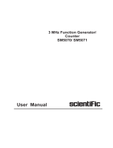
DDS DDS also works by generating addresses to a waveform RAM to produce
data for a DAC. However, unlike earlier techniques, the clock is a fixed fre-
quency reference. Instead of using a counter to generate addresses, an ad-
der is used. On each clock cycle, the contents of a Phase Increment Register
are added to the contents of the Phase Accumulator. The Phase Accumula-
tor output is the address to the waveform RAM (see diagram below). By
changing the Phase Increment the number of clock cycles needed to step
Phase
Increment
Register
48 Bits
Phase
Accumulator
48 bits
Modulation CPU
External Control
Modulation RAM
Waveform
RAM
16k points
DAC
Fixed
Frequency
Filter
Fixed
Frequency
Reference
DDS ASIC
Direct Digital Synthesis
+
Figure 1: Block diagram
of SRS DDS ASIC
2-1

Introduction
2-2
through the entire waveform RAM changes, thus changing the output fre-
quency.
Frequency changes now can be accomplished phase continuously in only
one clock cycle. And the fixed clock eliminates phase jitter and requires only
a simple fixed frequency anti-aliasing filter at the output.
The DS345 uses a custom Application Specific Integrated Circuit (ASIC) to
implement the address generation in a single component. The frequency res-
olution is equal to the resolution with which the Phase Increment can be set.
In the DS345, the phase registers are 48 bits long, resulting in an impressive
1:10
14
frequency resolution. The ASIC also contains a modulation control
CPU that operates on the Phase Accumulator, Phase Increment, and exter-
nal circuitry to allow digital synthesis and control of waveform modulation.
The Modulation CPU uses data stored in the Modulation RAM to produce
amplitude, frequency, phase, and burst modulation, as well as frequency
sweeps. All modulation parameters, such as rate, frequency deviation, and
modulation index, are digitally programmed.
DDS gives the DS345 greater flexibility and power than conventional synthe-
sizers or arbitrary waveform generators without the drawbacks inherent in
PLL designs.
DS345 Description
40MHz Clock
DDS345 ASIC
Modulation RAM
Waveform
RAM
12 bit
DAC
10 MHz Bessel Filter
Cauer Filter
x2
Amplitude DAC Amplitude
Control
Output
Amp
Attenuators
Function
Output
Square Wave
Comparator
Sync
Output
AM Input
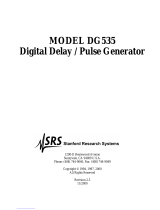
Figure 2: DS345 Block Diagram
A block diagram of the DS345 is shown in Figure 2. The heart of the DS345
is a 40 MHz crystal clock. This clock is internally provided, but may be phase
locked to an external reference. The 40 MHz clock controls the DDS345
ASIC, waveform RAM, and high-speed 12bit DAC. Sampling theory limits
the frequency of the waveform output from the DAC to about 40% of 40 MHz,
or 15 MHz. The 48 bit length of the DDS345's PIR's sets the frequency reso-
lution to about 146 nHz. These parameters and the DAC's 12 bit resolution
define the performance limits of the DS345.

Introduction
2-3
The reconstruction filter is key to accurately reproducing a waveform in a
sampled data system. The DS345 contains two separate filters. For sine
w
ave generation the output of the DAC goes through a 9
th
order Cauer filter,
while ramps, triangles, and arbitrary waveforms pass instead through a
10
MHz 7
th
order Bessel filter. The Cauer filter has a cutoff frequency of 16.5
MHz and a stopband attenuation of 85dB, and also includes a peaking circuit
to correct for the sine(x)/x amplitude response characteristic of a sampled
system. This filter eliminates any alias frequencies from the waveform output
and allows generation of extremely pure sine waves. The output of the Cauer
filter is then frequency doubled by an analog multiplier. This multiplies the
DAC's 0 - 15 MHz output frequency range to the final 0 - 30 MHz range. How-
ever, the Cauer filter has very poor time response and is only useful for CW
waveforms. Therefore, the Bessel filter was chosen for its ideal time re-
sponse, eliminating rings and overshoots from stepped waveform outputs.
This filter limits the frequency of arbitrary waveforms to 10 MHz and rise
times to 35 ns.
The output of the filters pass to an analog multiplier that controls the ampli-
tude of the waveform. This multiplier controls the waveform amplitude with an
AM signal that may come from either the ASIC or the external AM input. This
allows both internally and externally controlled amplitude modulation. The
amplitude control is followed with a wide bandwidth power amplifier that out-
puts 10 V peak-to-peak into a 50 ohm load with a rise time of less than 15 ns.
The output of the power amplifier passes through a series of three step atten-
uators (6, 12, and 24 dB) that set the DS345's final output amplitude. The
post amplifier attenuators allow internal signal levels to remain as large as
possible, minimizing output noise and signal degradation.
Square waves and waveform sync signals are generated by discriminating
the function waveform with a high-speed comparator. The output of the com-
parator passes to the SYNC OUTPUT and, in the case of square waves, to
the amplitude control multiplier input. Generating square waves by discrimi-
nating the sine wave signal produces a square wave output with rise and fall
times much faster than allowed by either of the signal filters.

Introduction
2-4
Page is loading ...
Page is loading ...
Page is loading ...
Page is loading ...
Page is loading ...
Page is loading ...
Page is loading ...
Page is loading ...
Page is loading ...
Page is loading ...
Page is loading ...
Page is loading ...
Page is loading ...
Page is loading ...
Page is loading ...
Page is loading ...
Page is loading ...
Page is loading ...
Page is loading ...
Page is loading ...
Page is loading ...
Page is loading ...
Page is loading ...
Page is loading ...
Page is loading ...
Page is loading ...
Page is loading ...
Page is loading ...
Page is loading ...
Page is loading ...
Page is loading ...
Page is loading ...
Page is loading ...
Page is loading ...
Page is loading ...
Page is loading ...
Page is loading ...
Page is loading ...
Page is loading ...
Page is loading ...
Page is loading ...
Page is loading ...
Page is loading ...
Page is loading ...
Page is loading ...
Page is loading ...
Page is loading ...
Page is loading ...
Page is loading ...
Page is loading ...
Page is loading ...
Page is loading ...
Page is loading ...
Page is loading ...
Page is loading ...
Page is loading ...
Page is loading ...
Page is loading ...
Page is loading ...
Page is loading ...
Page is loading ...
Page is loading ...
Page is loading ...
Page is loading ...
Page is loading ...
Page is loading ...
Page is loading ...
Page is loading ...
Page is loading ...
Page is loading ...
Page is loading ...
Page is loading ...
Page is loading ...
Page is loading ...
Page is loading ...
Page is loading ...
Page is loading ...
Page is loading ...
Page is loading ...
Page is loading ...
Page is loading ...
Page is loading ...
Page is loading ...
Page is loading ...
Page is loading ...
Page is loading ...
Page is loading ...
Page is loading ...
Page is loading ...
Page is loading ...
Page is loading ...
Page is loading ...
Page is loading ...
Page is loading ...
Page is loading ...
Page is loading ...
Page is loading ...
Page is loading ...
Page is loading ...
Page is loading ...
Page is loading ...
Page is loading ...
Page is loading ...
Page is loading ...
Page is loading ...
Page is loading ...
Page is loading ...
Page is loading ...
Page is loading ...
Page is loading ...
Page is loading ...
Page is loading ...
Page is loading ...
Page is loading ...
Page is loading ...
Page is loading ...
Page is loading ...
Page is loading ...
Page is loading ...
-
 1
1
-
 2
2
-
 3
3
-
 4
4
-
 5
5
-
 6
6
-
 7
7
-
 8
8
-
 9
9
-
 10
10
-
 11
11
-
 12
12
-
 13
13
-
 14
14
-
 15
15
-
 16
16
-
 17
17
-
 18
18
-
 19
19
-
 20
20
-
 21
21
-
 22
22
-
 23
23
-
 24
24
-
 25
25
-
 26
26
-
 27
27
-
 28
28
-
 29
29
-
 30
30
-
 31
31
-
 32
32
-
 33
33
-
 34
34
-
 35
35
-
 36
36
-
 37
37
-
 38
38
-
 39
39
-
 40
40
-
 41
41
-
 42
42
-
 43
43
-
 44
44
-
 45
45
-
 46
46
-
 47
47
-
 48
48
-
 49
49
-
 50
50
-
 51
51
-
 52
52
-
 53
53
-
 54
54
-
 55
55
-
 56
56
-
 57
57
-
 58
58
-
 59
59
-
 60
60
-
 61
61
-
 62
62
-
 63
63
-
 64
64
-
 65
65
-
 66
66
-
 67
67
-
 68
68
-
 69
69
-
 70
70
-
 71
71
-
 72
72
-
 73
73
-
 74
74
-
 75
75
-
 76
76
-
 77
77
-
 78
78
-
 79
79
-
 80
80
-
 81
81
-
 82
82
-
 83
83
-
 84
84
-
 85
85
-
 86
86
-
 87
87
-
 88
88
-
 89
89
-
 90
90
-
 91
91
-
 92
92
-
 93
93
-
 94
94
-
 95
95
-
 96
96
-
 97
97
-
 98
98
-
 99
99
-
 100
100
-
 101
101
-
 102
102
-
 103
103
-
 104
104
-
 105
105
-
 106
106
-
 107
107
-
 108
108
-
 109
109
-
 110
110
-
 111
111
-
 112
112
-
 113
113
-
 114
114
-
 115
115
-
 116
116
-
 117
117
-
 118
118
-
 119
119
-
 120
120
-
 121
121
-
 122
122
-
 123
123
-
 124
124
-
 125
125
-
 126
126
-
 127
127
-
 128
128
-
 129
129
-
 130
130
-
 131
131
-
 132
132
-
 133
133
-
 134
134
-
 135
135
-
 136
136
-
 137
137
-
 138
138
-
 139
139


Ask a question and I''ll find the answer in the document
Finding information in a document is now easier with AI
Related papers
Other documents
-
 Scientific SMG4000 Series Owner's manual
-
GW Instek tware User manual
-
-
 Scientific SM5071 Owner's manual
-
-
-
 Liquid Instruments Moku:Go Waveform Generator User manual
-
-
 Stanford Research Systems DG535 Operation And Service Manual
-


