BEA IXIO-DT1V User guide

Type
User guide

This manual is also suitable for

BEA IXIO-DT1V is a sensor that offers both activation and safety functions for pedestrian doors. It features radar technology for motion detection and infrared technology for presence detection, ensuring reliable and safe operation. With its adjustable radar and infrared fields, the device can be customized to suit specific needs and environments. The IXIO-DT1V also includes a camera cover accessory, allowing for easy integration with surveillance systems.

BEA IXIO-DT1V is a sensor that offers both activation and safety functions for pedestrian doors. It features radar technology for motion detection and infrared technology for presence detection, ensuring reliable and safe operation. With its adjustable radar and infrared fields, the device can be customized to suit specific needs and environments. The IXIO-DT1V also includes a camera cover accessory, allowing for easy integration with surveillance systems.

2
14
3
87
6
5
4
5
3
87
6
10 11
11
9
12
75.5960.07 IXIO FAMILY 20230823 Page 1 of 12
MOTION AND PRESENCE SENSOR FOR
AUTOMATIC SLIDING DOORS
10IMB
Bracket accessory
All IXIOs All IXIOs (except DT1 V) All IXIOs (except DT1 V) All IXIOs (except DT1 V)
All IXIOs All IXIOs All IXIOs
10.1279
Camera cover accessory
ENGLISH
IXIO-DT1: activation and safety for pedestrian doors
IXIO-ST: safety for pedestrian doors
IXIO-DT1 V: IXIO-DT1 + camera cover accessory
IXIO-DT1 INDUSTRIAL: activation and safety for
industrial doors
IXIO-ST INDUSTRIAL: safety for industrial doors
1. radar antenna (wide field)
2. radar antenna (narrow field)
3. LCD
4. AIR curtain width adjustment
5. AIR lenses
6. main connector
7. main adjustment knob
8. AIR curtain angle adjustment knob
9. IXIO-DT1 / IXIO ST cover
10. IXIO-DT1 V cover
11. LED
12. camera
10ICA
Ceiling accessory
10CDA
Curved door accessory
10URA
Universal rain accessory
35.1286: black cover
35.1302: white cover
35.1303: silver cover
10IXIOSPACER
Spacer
PRODUCT FAMILY
ACCESSORIES
IXIO FAMILY
x
Page 2 of 12 75.5960.07 IXIO FAMILY 20230823
LED SIGNALS
COLORS BEHAVIORS
(green)
Motion detection (DT1 sensors)
AUX (ST sensors)
(red)
Presence detection
LED flashes
LED flashes quickly LED is off
LED flashes x times
LED flashes red-green
INSTALLATION
The sensor should be
mounted securely to avoid
extreme vibrations.
Avoid highly reflective
objects in the infrared field.
Avoid moving objects and
light sources in the detection
field.
Do not cover the sensor.
Only trained and qualified
personnel are recommended
for installation and setup of
the sensor.
The warranty is invalid if
unauthorized repairs are
made or attempted by
unauthorized personnel.
Following installation, always
test for proper operation
(according to ANSI 156.10)
before leaving the premises.
The door control unit and the
header cover profile must be
correctly grounded.
SAFETY
It is recommended to clean
the optical parts at least once
a year or more if required due
to environmental conditions.
Do not use aggressive
products to clean
the optical parts.
MAINTENANCE
READ BEFORE BEGINNING INSTALLATION/PROGRAMMING/SETUP
This device can be expected to comply with Part 15 of the FCC Rules, provided it is assembled in exact accordance with the instructions
provided with this kit. Operation is subject to the following conditions: (1) this device may not cause harmful interference, and (2) this
device must accept any interference received, including interference that may cause undesired operation.
...
75.5960.07 IXIO FAMILY 20230823 Page 3 of 12
READ BEFORE BEGINNING INSTALLATION/PROGRAMMING/SET-UP
Pressing a parameter symbol on your remote control displays the saved value
directly on the LCD screen. Do not unlock first.
To adjust contrast, push and turn
the grey button simultaneously.
During normal function only.
Negative display = active output
= scroll = select
3) Select language before entering the first LCD menu.
During the first 30 seconds after power-on of the
sensor or later in the diagnostics menu.
Select Back to
return to previous
menu or display.
Select More to go to next level:
- basic settings (MENU 1)
- advanced settings (MENU 2)
- diagnostics (MENU 3)
1) Push to enter the LCD menu.
1) Navigate to menu 3 (Diagnostics). 2) Select "ZIP code". 3) Change the code as desired.
displayed value
=
factory value
displayed value
=
saved value
Activation
impulse
Safety
2) Enter password, if necessary.
Not during the first minute after
power-on of the sensor.
Password
XX X X
ZIP code
V
To activate the new ZIP code, you must validate the last digit (see below):
v = valid ZIP code (values will be changed accordingly)
x = invalid ZIP code (no values will be changed)
v/x = valid ZIP code, but from a different product
*only available values
will be changed*
ZIP code
H24 1 56-KG4
01 0 800/02F
ZIP code
ID #
ZIP code
E24 1 56-KG4
01 0 800/02F
ZIP code
E24 1 56-KG4
01 0 800/02F
ZIP code
E24 1 56-KG4
01 0 800/02F
ZIP code
H24 1 56-KG4
01 0 800/02F
HOW TO USE THE LCD
DISPLAY DURING NORMAL FUNCTION
FACTORY VALUE VS. SAVED VALUE
NAVIGATING IN MENUS
CHANGING A ZIP CODE
VALUE CHECK WITH REMOTE CONTROL
See application note on ZIP CODE (76.0024).
1
Page 4 of 12 75.5960.07 IXIO FAMILY 20230823
* The sensor LED will briefly flash RED during
monitoring communication with door control.
This indicates that external monitoring is
functional. Monitoring functionality must
be active on the sensor, door control, and
monitoring wires must be properly connected to
the door control.
CAMERA HARNESS FOR DT1 V
Mounting is compatible with the WIZARD.
Using the provided mounting template, mount the sensor, ensuring that the bottom of the sensor is
within 2 inches of the bottom of the door header.
Refer to Application Note 76.0035 if an IXIO Spacer is required for the given application.
Route the harness using the harness clip as shown in the exploded view of the mounting illustration.
MOUNTING
RED
SENSOR
DOOR CONTROL
BLACK
BROWN
BLUE
WHITE (COM)
YELLOW (N.C)
GREEN (N.O.)
PURPLE
PURPLE
POWER SUPPLY
POWER SUPPLY
SAFETY INPUT
SAFETY INPUT
TEST OUTPUT*
TEST OUTPUT*
OPENING INPUT
OPENING INPUT
OPENING INPUT
Sensor connectivity (power and relays) must utilize only the supplied harness.
Sensor power (and camera power if using the DT1 V) must be supplied from a Class 2 supply source limited to 15 W.
Sensor is intended to be monitored for proper operation by the door operator or system.
Harness shall be routed separated from any Mains or non-Class 2 voltage cable for correct operation or shall be rated for the Mains
voltage, and suitable protection and routing means shall be used according to National and Local Codes to prevent damage to the
harness and/or IXIO sensor.
WIRING
RCA VIDEO OUT (female)
Voltage
Regulator
POWER
6 – 28 VAC ±10%
6.6 – 36 VDC ±10%
max. 2 in
MOUNTING & WIRING
VOLTAGE
Power: 12 – 24 VAC, 50/60 Hz
12 – 30 VDC
2.5 W (max)
Test: low: < 1 V
high: > 10 V (30 V max.)
response time: typ. < 5 ms
2
75.5960.07 IXIO FAMILY 20230823 Page 5 of 12
RADAR OPENING IMPULSE FIELD (DT1 SENSORS ONLY)
ANGLE
field size: 9
immunity: 2
field size: 9
immunity: 2
The size of the detection field varies according to the mounting height of the sensor.
The following graphics are representations – not default settings.
from 15° to 45°, default 30 °
from -15° to 15°, default 0°
WIDTH
field size: 9
immunity: 2
field size: 9
immunity: 2
13’ x 6’6" (wide)
6’6" x 8’ (narrow)
1 × 1 grid is approximately 3.28 ft × 3.28 ft.
7.2 ft
7.2 ft
7.2 ft
7.2 ft
C1
C2
3
x2
Page 6 of 12 75.5960.07 IXIO FAMILY 20230823
INFRARED SAFETY FIELD
If necessary, adjust the AIR curtain angle
(from -7° to 4°, default 0°).
Activate the visible spots to verify the position of the AIR curtain.
Visibility depends on external conditions. When spots are not visible, use
the Spotfinder to locate the curtains.
ANGLE
DOOR
max. 3 in
The distance between the inner curtain of the inside
door sensor and the inner curtain of the outside
door sensor should always be smaller than 8 in.
C1 = closest to sliding door
C2 = farthest from sliding door
Part of the detection field can be masked to reduce its width. The arrow position determines the width of the detection field.
The size of the detection field varies according to the mounting height and the settings of the sensor.
Wide setting has 1:1 ratio. For example, a 6-foot mounting height will project a 6-foot detection width at floor.
WIDTH
Always verify the actual detection field width by walk-testing according to ANSI 156.10.
Additional adjustments are possible by LCD or remote control
(see OVERVIEW OF SETTINGS).
OR
CLOSERCLOSER
AWAYAWAY
OU
x2
+
+
+
2 s
4 s
4
75.5960.07 IXIO FAMILY 20230823 Page 7 of 12
SETUP
Set up the sensor using either push-buttons or the remote control.
TEST THE PROPER OPERATION OF THE INSTALLATION BEFORE LEAVING THE PREMISES!
SETUP 1 QUICK
SETUP 2 ASSISTED
test of full door cycle + reference picture
either hold the knob for 2 seconds, or use the remote
control buttons as specified
either hold the knob for 4 seconds, or use the remote
control buttons as specified
STEP OUT OF THE INFRARED FIELD!
+
+
0 987654321
Page 8 of 12 75.5960.07 IXIO FAMILY 20230823
all parameter settings in zipped format (see application note on ZIP CODE 76.0024)
unique ID-number
last 10 errors + day indication
view of spot(s) that trigger detection
signal amplitude received on curtain
signal amplitude received on curtain 2
OVERVIEW OF SETTINGS
Back
Back
Back
More
More
More
More
Back
RAD: FIELDSIZE
RAD: FIELDSIZE
RAD: IMMUNITY
RAD: DIRECTION
RAD: HOLDTIME
RAD: REENTRY
RAD: OUTPUT
AIR: WIDTH
AIR: OUTPUT
TEST
BASICADVANCEDDIAGNOSTICS
factory value
RC BUTTONS
see note 1
see note 2
see note 3
see note 4
see note 2
see note 2
see note 3
see note 5
see note 6
see note 1
small
small
small
0.5 s
>
>
>
8 s
highlow
large
large
large
9 s
>
>
> >
6 s
>
>
>
7 s
>
>
>
>
5 s
>
>
>
>
4 s
>
>
>
>
3 s
>
>
>
>
1 s
>
>
>
>
2 s
>
uni
MTF
unioff bi
onoff
AIR: IMMUNITY
AIR: WIDTH
AIR: NUMBER
AIR: FREQ
AIR: OUTPUT
TEST
REDIRECTION
FACTORY RESET
AIR: PRESENCE TIME
ZIP CODE
ID #
CONFIG P/N
SOFT P/N
ERROR LOG
AIR: SPOTVIEW
AIR: C1 ENERG
AIR: C2 ENERG
POWERSUPPLY
OPERATINGTIME
RESET LOG
PASSWORD
ADMIN
supply voltage at power connector
power duration since first startup
delete all saved errors
LCD and remote control password (0000= no password)
enter code to access admin mode
normal
60 min
partial
reset
infinte
full
reset
10 min
mode B
20 min5 min2 min1 min
enhanced
1
A
30 s
2
B
on
R1 MW or IR
R2 IR
off
R1 MW
R2 IR
DeEner/NO
Energ/NC
DeEner/NO
Energ/NC
DeEner/NO
Energ/NC
Energ/NC
Energ/NC
Energ/NC
Energ/NC
Energ/NC
Energ/NC
Energ/NC
DeEner/NO
Energ/NC
DeEner/NO
Energ/NC
DeEner/NO
DeEner/NO
DeEner/NO
DeEner/NO
DeEner/NO
DeEner/NO
DeEner/NO
highlighted red = ST sensors only
highlighted blue = DT sensors only Download the BEA DECODER app
for a quick overview of settings
DIAGNOSTICS
75.5960.07 IXIO FAMILY 20230823 Page 9 of 12
OVERVIEW OF SETTINGS (cont.)
RC BUTTONS NOTES
Note 1 Always use a screwdriver when making further AIR adjustments to the arrow position on the
sensor.
Note 2 DeEner = de-energized relay
Energ = energized relay
NO = normally open
NC = normally closed
Note 3 The sensor LED will briefly flash RED during monitoring communication with door control. This
indicates that external monitoring is functional.
Monitoring functionality must be active on the sensor and door control, and monitoring wires
must be properly connected to the door control.
Note 4 MTF = motion tracking feature
Note 5 REDIRECTION setting (F1 on remote control):
R1-MW, R2-IR (F1=0):
R1 = MW (i.e. motion detection)
R2 = IR (i.e. presence detection)
R1-MW or IR, R2-IR (F1=1):
R1 = MW or IR (i.e. motion or presence detection)
R2 = IR (i.e. presence detection)
Note 6 partial: outputs are not reset
2
1
4
5
8
E1
E2
E4
E5
E8
Page 10 of 12 75.5960.07 IXIO FAMILY 20230823
TROUBLESHOOTING
ORANGE LED flashes
1x The sensor signals an
internal fault. Replace sensor.
ORANGE LED flashes
2x The power supply voltage
is too low/high. Check power supply voltage in diagnotistics
menu (menu 3) of the LCD.
Check wiring.
ORANGE LED flashes
4x The sensor does not receive
enough AIR energy. Decrease the angle of the AIR curtains.
Increase the AIR immunity filter.
Deactivate curtain #2 (C2, outer curtain).
ORANGE LED flashes
5x The sensor receives too
much AIR energy. Slightly increase the angle of the AIR curtains.
Decrease the AIR immunity filter.
The sensor is distrubed by
external elements. Eliminate the cause of disturbance (lamps,
rain cover, door controller housing properly
grounded).
ORANGE LED flashes
8x AIR power emitter is faulty. Replace sensor.
ORANGE LED is on The sensor encounters a
memory problem. Cut and restore power supply.
If ORANGE LED illuminates again, replace the
sensor.
RED LED flashes quickly
after an assisted setup The sensor sees the door
during assisted setup. Move the AIR curtains away from the door.
Install the sensor as close to the door as
possible. If needed, use a bracket assembly.
Ensure that the bottom of the sensor is
mounted within 2” of the bottom of the door
header.
Launch a new assisted setup.
RED LED illuminates
sporadically The sensor vibrates. Check if the sensor is secure.
Check position of cable and cover.
The sensor sees the door. Adjust the AIR angle and launch an assisted
setup.
The sensor is disturbed by
external conditions. Increase the AIR immunity filter.
GREEN LED illuminates
sporadically The sensor is disturbed by
rain and/or leaves. Increase radar immunity filter.
Ghosting created by door
movement. Change radar field angle.
The sensor vibrates. Check if the sensor and door cover is secure.
Check position of cable and cover.
The sensor sees the door or
other moving objects. Remove the objects if possible.
Change radar field size, angle, or immunity.
troubleshooting continues on the next page
75.5960.07 IXIO FAMILY 20230823 Page 11 of 12
TROUBLESHOOTING (cont.)
The LED and the LCD
displays are off
No power to sensor. Check wiring.
Check for correct power supply.
The reaction of
the door does not
correspond with the
LED signal
Incorrect output
configuration / wiring.
Check output configuration setting.
Check wiring.
The LCD or remote
control does not react
The sensor is protected by
a password.
Enter the correct password. If you forgot the
code, cut and restore the power supply to
access the sensor without entering a password
during 1 minute.
RED Visible External
Monitoring (Test
Indication LED) does
not flash
Monitoring installation/
setup error.
Verify door control is capable of monitoring
and the sensor monitoring wires are properly
connected to the door control.
Verify monitoring (TEST) is ON in the sensor
settings.
Sensor malfunction. Replace the sensor.
RED Visible External
Monitoring (Test
Indication LED) flashes
continuously
Wiring issue. Verify wiring.
Door control not set
correctly.
Verify door control monitoring set to Active
Low.
Door cycles open and
remains open
Door control monitoring
set to Active High.
Set door control monitoring to Active Low.
Safety output is set
incorrectly.
Set the safety output required for the door
control.
TECHNICAL SPECIFICATIONS
SENSOR
Specifications are subject to change without prior notice.
All values measured in specific conditions.
Supply voltage: 12 – 24 VAC ±10%
12 – 30 VDC ±10% to be operated from SELV-compatible power supplies only
Power consumption: < 2.5 W
Mounting height: 6’6” – 11’6” local regulations may impact acceptable mounting height (pedestrian applications only)
Temperature range:
(sensor)
-13 – 131 °F *
0 – 95% relative humidity, non-condensing
LCD screen is operational from 14 131 °F.
The sensor may still be programmed in colder
temperatures, but with the remote control.
Degree of protection: IP54
Noise: < 70 dB
Applicable directives: R&TTE 1999/5/EC
MD 2006/42/EC
LVD 2006/95/EC
ROHS 2 2011/65/EU
Can’t find your answer?
Visit www.beainc.com or scan QR code for Frequently Asked Questions!
Page 12 of 12 75.5960.07 IXIO FAMILY 20230823
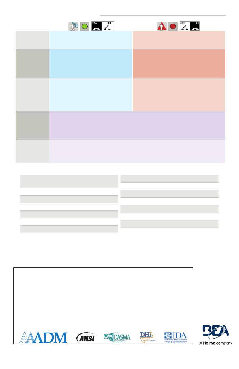
Detection mode: DT1 SENSORS:
MOTION
minimum detection speed: 2 in/s
DT1 & ST SENSORS:
PRESENCE
typical response time: < 200 ms (max: 500 ms)
Technology: DT1 SENSORS:
Microwave doppler radar
Transmitter frequency: 24.150 GHz
Transmitter radiated power: < 20 dBm EIRP
Transmitter power density: < 5 mW/cm2
DT1 & ST SENSORS:
Active infrared with background analysis
Spot: 2" × 2" (typ)
Number of spots: max. 24 per curtain
Number of curtains: 2
Output: DT1 & ST SENSORS:
Electromechanical relay
(potential and polarity free)
Max. contact current: 1 A
Max. contact voltage: 30 VDC
Adjustable Hold time: 0.5 – 9 s
DT1 & ST SENSORS:
Solid-state relay
(potential and polarity free)
Max. contact current: 400 mA
Max. contact voltage: 42 VAC / VDC
Hold time: 0.3 – 1 s
Test/Monitoring
input:
DT1 & ST SENSORS:
Sensitivity:
Low: < 1 V
High: > 10 V (max. 30 V)
Response time on test request: typical < 5 ms
Norm conformity: DT1 & ST SENSORS:
ISO 13849-1:2008 PL «c» CAT. 2
(under the condition that the door control system monitors the sensor at least once per door cycle)
IEC 61496-1:2012 ESPE Type 2
CAMERA
Specifications are subject to change without prior notice.
All values measured in specific conditions.
Voltage regulator
(built into wire harness):
6.6 – 36 VDC (±10%)
6 – 28 VAC (±10%)
Operating temperature: -22 – 140 °F (max. RH: 95%)
Video output: 1.0 (Vp-p) / 75Ω
Image Sensor: CMOS
Horizontal resolution: 480 TVL
NTSC output: 720 (H) × 480 (V)
Sync system: Inter-Sync
Frame rate: 30 fps
Minimum illumination: 0.01 LUX
AE control: auto
Gain control: auto
Electronic shutter: 1 s ~ 1/10,000s
S/N ratio: > 50 dB
AWB: Auto
TECHNICAL SPECIFICATIONS (cont.)
Tech Support & Customer Service: 1-800-523-2462
General Tech Questions: [email protected] | Tech Docs: www.BEAsensors.com
BEA, Inc., the sensor manufacturer, cannot be held responsible for incorrect installations or incorrect adjustments of the sensor/device;
therefore, BEA, Inc. does not guarantee any use of the sensor/device outside of its intended purpose.
BEA, Inc. strongly recommends that installation and service technicians be AAADM-certifi ed for pedestrian doors, IDA-certifi ed for doors/
gates, and factory-trained for the type of door/gate system.
Installers and service personnel are responsible for executing a risk assessment following each installation/service performed, ensuring
that the sensor/device system performance is compliant with local, national, and international regulations, codes, and standards.
Once installation or service work is complete, a safety inspection of the door/gate shall be performed per the door/gate manufacturer’s
recommendations and/or per AAADM/ANSI/DASMA guidelines (where applicable) for best industry practices. Safety inspections must
be performed during each service call – examples of these safety inspections can be found on an AAADM safety information label (e.g.
ANSI/DASMA 102, ANSI/DASMA 107, UL294, UL325, and International Building Code).
Verify that all appropriate industry signage, warning labels, and placards are in place.
BEA, INC. INSTALLATION/SERVICE COMPLIANCE EXPECTATIONS
©BEA | Original Instructions | PLEASE KEEP FOR FURTHER USE - DESIGNED FOR COLOR PRINTING
  • Page 1 1
  • Page 2 2
  • Page 3 3
  • Page 4 4
  • Page 5 5
  • Page 6 6
  • Page 7 7
  • Page 8 8
  • Page 9 9
  • Page 10 10
  • Page 11 11
  • Page 12 12

BEA IXIO-DT1V User guide

Type
User guide
This manual is also suitable for

BEA IXIO-DT1V is a sensor that offers both activation and safety functions for pedestrian doors. It features radar technology for motion detection and infrared technology for presence detection, ensuring reliable and safe operation. With its adjustable radar and infrared fields, the device can be customized to suit specific needs and environments. The IXIO-DT1V also includes a camera cover accessory, allowing for easy integration with surveillance systems.

Ask a question and I''ll find the answer in the document

Finding information in a document is now easier with AI