BEA IXIO-DT1 INDUSTRIAL User guide

Type
User guide

This manual is also suitable for

IXIO-DT1
! !
1
75.1219.01 IXIO-DT1 QG 20230913 Page 1 of 4
ENGLISH
READ BEFORE BEGINNING INSTALLATION & SETUP
This device can be expected to comply with Part 15 of the FCC Rules, provided it is assembled in
exact accordance with the instructions provided with this kit. Operation is subject to the following
conditions: (1) this device may not cause harmful interference, and (2) this device must accept any
interference received, including interference that may cause undesired operation.
Only trained and
qualified personnel
are recommended for
installation and setup of the
sensor.
The warranty is invalid if
unauthorized repairs are
made or attempted by
unauthorized personnel.
Following installation,
always test for proper
operation (according to
ANSI 156.10) before leaving
the premises.
The door control unit
and the header cover
profile must be correctly
grounded.
The sensor should be
mounted securely to
avoid extreme vibrations.
Avoid highly reflective
objects in the infrared
field.
Avoid moving objects
and light sources in the
detection field.
Do not cover the sensor.
QUICK GUIDE
MOTION AND PRESENCE SENSOR FOR
AUTOMATIC SLIDING DOORS
Refer to the User’s Guide
for full instructions.
max. 2 in
RED
SENSOR
DOOR CONTROL
BLACK
BROWN
BLUE
WHITE (COM)
YELLOW (N.C)
GREEN (N.O.)
PURPLE
PURPLE
POWER SUPPLY
POWER SUPPLY
SAFETY INPUT
SAFETY INPUT
TEST OUTPUT*
TEST OUTPUT*
OPENING INPUT
OPENING INPUT
OPENING INPUT
Sensor connectivity (power and relays) must utilize only the supplied harness.
Sensor power must be supplied from a Class 2 supply source limited to 15 W.
Sensor is intended to be monitored for proper operation by the door operator or system.
Harness shall be routed separated from any Mains or non-Class 2 voltage cable for correct operation or shall be rated for the
Mains voltage, and suitable protection and routing means shall be used according to National and Local Codes to prevent damage
to the harness and/or IXIO sensor.
Refer to Application Note 76.0035 if an IXIO Spacer is required for the given application.
POWER
12 – 24 VAC/VDC
12 – 30 VDC
2.5 W (max)
TEST
low: < 1 V
high: > 10 V (30 V max.)
response time: typ. < 5 ms
MOUNTING & WIRING
+
+
+
2 s
4 s
2
4
3
x
Page 2 of 4 75.1219.01 IXIO-DT1 QG 20230913
LED SIGNALS
ANGLE WIDTH
CLOSERCLOSER
AWAYAWAY
Activate the visible spots. Adjust the angle, if necessary.
ANGLE
WIDTH
SETUP 1 QUICK
reference picture
TILT WIDEROTATE NARROW
SETUP 2 ASSISTED
test of full door cycle + reference picture
either hold the knob for 2 seconds, or use the
remote control buttons as specified
either hold the knob for 4 seconds, or use the
remote control buttons as specified
OR
OR
Always verify the actual detection field width by walk-testing according to ANSI 156.10.
DOOR
max.
3 in
STEP OUT OF THE INFRARED FIELD!
TEST THE PROPER OPERATION OF THE INSTALLATION BEFORE LEAVING THE PREMISES!
RADAR OPENING IMPULSE FIELD
INFRARED SAFETY FIELD
SETUP
COLORS BEHAVIORS
(green)
Motion detection
(red)
Presence detection
LED flashes
LED flashes quickly LED is off
LED flashes x times
LED flashes red-green
C1
C2
or or
BASICADVANCEDDIAGNOSTICSDIAGNOSTICS
+
+
0 987654321
75.1219.01 IXIO-DT1 QG 20230913 Page 3 of 4
all parameter settings in zipped format (see application note on ZIP CODE 76.0024)
unique ID-number
last 10 errors + day indication
view of spot(s) that trigger detection
signal amplitude received on curtain
signal amplitude received on curtain 2
supply voltage at power connector
power duration since first startup
OVERVIEW OF SETTINGS
Back
Back
Back
More
More
More
More
Back
RAD: FIELDSIZE
RAD: SHAPE
RAD: FIELDSIZE
RAD: IMMUNITY
RAD: DIRECTION
RAD: HOLDTIME
RAD: REENTRY
RAD: OUTPUT
AIR: WIDTH
AIR: OUTPUT
TEST
BASICADVANCEDDIAGNOSTICS
factory value
RC BUTTONS
see note 1
see note 2
see note 3
see note 4
see note 2
see note 3
see note 5
see note 6
see note 1
small
small
small
0.5 s
>
>
>
8 s
highlow
large
LCD: "narrow" and "wide" setting options (default = wide)
Remote Control: = wide, = narrow
large
large
9 s
>
>
> >
6 s
>
>
>
7 s
>
>
>
>
5 s
>
>
>
>
4 s
>
>
>
>
3 s
>
>
>
>
1 s
>
>
>
>
2 s
>
unioff bi
onoff
AIR: IMMUNITY
AIR: WIDTH
AIR: NUMBER
AIR: FREQ
AIR: OUTPUT
TEST
REDIRECTION
FACTORY RESET
AIR: PRESENCE TIME
ZIP CODE
ID #
CONFIG P/N
SOFT P/N
ERROR LOG
AIR: SPOTVIEW
AIR: C1 ENERG
AIR: C2 ENERG
POWERSUPPLY
OPERATINGTIME
RESET LOG
PASSWORD
ADMIN
delete all saved errors
LCD and remote control password (0000= no password)
enter code to access admin mode
normal
60 min
full
reset
infinte
partial
reset
10 min
mode B
20 min5 min2 min1 min
enhanced
1
A
30 s
2
B
on
R1 MW or IR
R2 IR
off
R1 MW
R2 IR
DeEner/NO
NC
DeEner/NO
NC
DeEner/NO
NC
Energ/NC
NC
Energ/NC
NC
Energ/NC
NC
Energ/NC
NO
Energ/NC
NO
Energ/NC
NO
DeEner/NO
NO
DeEner/NO
NO
DeEner/NO
NO
DIAGNOSTICS
(green)
motion
(red)
presence
see note 2
Download the BEA DECODER app
for a quick overview of settings
MTF uni +
reentry
Page 4 of 4 75.1219.01 IXIO-DT1 QG 20230913
TECHNICAL SPECIFICATIONS
OVERVIEW OF SETTINGS (cont.)
©BEA | Original Instructions | PLEASE KEEP FOR FURTHER USE - DESIGNED FOR COLOR PRINTING
Specifications are subject to change without prior notice.
All values measured in specific conditions.
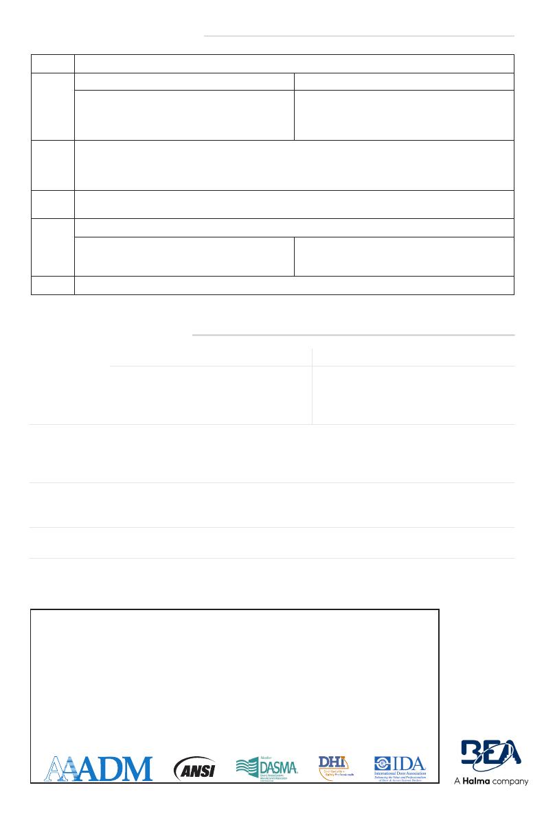
Output Relay 1 Relay 2
Electromechanical relay (potential and polarity free)
Max. contact current: 1 A
Max. contact voltage: 30 VAC
Adjustable hold time: 0.5 – 9 s
Solid-state relay (potential and polarity free)
Max. contact current: 100 mA
Max. contact voltage: 42 VDC / 30 VAC
Test/Monitoring
input:
Sensitivity:
Low: < 1 V
High: > 10 V (max. 30 V)
Response time on test request: typical < 5 ms
Supply voltage: 12 – 24 VAC ±10%
12 – 30 VDC ±10%
to be operated from SELV-compatible power supplies only
Mounting
height:
6’6” – 11’6”
local regulations may impact acceptable mounting height (pedestrian applications only)
Tech Support & Customer Service: 1-800-523-2462
General Tech Questions: [email protected] | Tech Docs: www.BEAsensors.com
BEA, Inc., the sensor manufacturer, cannot be held responsible for incorrect installations or incorrect adjustments of the sensor/device;
therefore, BEA, Inc. does not guarantee any use of the sensor/device outside of its intended purpose.
BEA, Inc. strongly recommends that installation and service technicians be AAADM-certifi ed for pedestrian doors, IDA-certifi ed for doors/
gates, and factory-trained for the type of door/gate system.
Installers and service personnel are responsible for executing a risk assessment following each installation/service performed, ensuring
that the sensor/device system performance is compliant with local, national, and international regulations, codes, and standards.
Once installation or service work is complete, a safety inspection of the door/gate shall be performed per the door/gate manufacturer’s
recommendations and/or per AAADM/ANSI/DASMA guidelines (where applicable) for best industry practices. Safety inspections must
be performed during each service call – examples of these safety inspections can be found on an AAADM safety information label (e.g.
ANSI/DASMA 102, ANSI/DASMA 107, UL294, UL325, and International Building Code).
Verify that all appropriate industry signage, warning labels, and placards are in place.
BEA, INC. INSTALLATION/SERVICE COMPLIANCE EXPECTATIONS
Note 1 Always use a screwdriver when making further AIR adjustments to the arrow position on the sensor.
Note 2 RADAR AIR
NO = normally open
NC = normally closed
DeEner = de-energized relay (active)
Energ = energized relay (passive)
NO = normally open
NC = normally closed
Note 3 The sensor LED will briefly flash RED during monitoring communication with door control. This indicates that external
monitoring is functional.
Monitoring functionality must be active on the sensor and door control, and monitoring wires must be properly
connected to the door control.
Note 4 MTF = uni-directional with motion-tracking feature
uni + reentry: BEA recommends only adjusting using the LCD
Note 5 REDIRECTION setting (F1 on remote control):
R1-MW, R2-IR (f1=0):
R1 = MW (i.e. motion detection)
R2 = IR (i.e. presence detection)
R1-MW or IR, R2-IR (F1=1):
R1 = MW or IR (i.e. motion or presence detection)
R2 = IR (i.e. presence detection)
Note 6 partial: outputs are not reset
  • Page 1 1
  • Page 2 2
  • Page 3 3
  • Page 4 4

BEA IXIO-DT1 INDUSTRIAL User guide

Type
User guide
This manual is also suitable for

Ask a question and I''ll find the answer in the document

Finding information in a document is now easier with AI