Page is loading ...

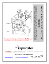
Installation, Operating &
Maintenance Instructions
906570EA
Edition
18.10.2018
Pump-out port system
Series 23
DN 16
–
40 mm (I. D.
5
/
8
"
–
1
1
/
2
")
This manual is valid for the following product ordering number/s:
23024-KA01-…., 23024-KEPS-….
23028-KA01-…., 23028-KEPS-….
23032-KA01-…., 23032-KEPS-….
Sample picture

Series
230
2
/
28
Edition
18.10.2018
9
06570EA
Imprint
Manufacturer
VAT Vakuumventile AG, CH-9469 Haag, Switzerland
Website:
Phone:
Fax:
Email:
www.vatvalve.com
+41 81 771 61 61
+41 81 771 48 30
Publisher
VAT Vakuumventile AG, CH-9469 Haag, Switzerland
Editor
VAT Vakuumventile AG, CH-9469 Haag, Switzerland
Print VAT Vakuumventile AG, CH-9469 Haag, Switzerland
Copyright © VAT Vakuumventile AG 2018
No part of these instructions may be reproduced in any way (photo-
copies, microfilms or any other reproduction processes) nor may it be
manipulated with electronic systems, duplicated or distributed without
written permission from VAT. Offenders are liable to pay damages.
The original VAT firmware and updated state of the art versions of the
VAT firmware are intended for use with VAT products. The VAT firmware
contains a limited, time unlimited user license. The VAT firmware may not
be used for purposes other than those intended nor is it permitted to
make copies of the VAT firmware. In particular, it is strictly forbidden to
give copies of the VAT firmware to other people.
The use of trade names, brand names, trademarks, etc. in these
Instructions does not entitle third parties to consider these names to be
unprotected and to use them freely. This is in accordance with the
meaning of the laws and acts covering brand names and trademarks.

Series 230
906570EA
Edition
18.10.2018
3
/
28
Contents
1
Description of product ........................................................................ 4
1.1
Identification of product.................................................................................... 4
1.2
Use of product ................................................................................................. 4
1.3
Related documents.......................................................................................... 4
1.4
Technical data ................................................................................................. 4
2
Safety ................................................................................................... 5
2.1
Compulsory reading material ........................................................................... 5
2.2
Danger levels .................................................................................................. 5
2.3
Personnel qualifications ................................................................................... 6
2.4
Safety labels .................................................................................................... 6
3
Design and Function ........................................................................... 7
3.1
Design ............................................................................................................. 7
3.2
Function .......................................................................................................... 7
4
Installation ........................................................................................... 8
4.1
Unpacking ....................................................................................................... 8
4.2
Installation into the system............................................................................... 9
4.2.1
Installation of pump-out port .............................................................. 10
4.2.2
Installation of valve mechanism ......................................................... 10
4.2.3
Connection Lines ............................................................................... 11
4.2.4
Admissible forces and bending moments ........................................... 11
5
Operation ........................................................................................... 12
5.1
Description .................................................................................................. 134
5.2
Opening the pump-out port ............................................................................ 13
5.3
Closing the pump-out port ............................................................................. 13
5.4
Trouble shooting ............................................................................................ 13
6
Maintenance ...................................................................................... 14
6.1
Maintenance intervals .................................................................................... 15
6.2
Required tools ............................................................................................... 15
6.3
Cleaning the valve mechanism ...................................................................... 16
6.4
Cleaning the pump-out port ........................................................................... 17
7
Repairs ............................................................................................... 19
8
Dismounting and Storage ................................................................. 20
8.1
Dismounting .................................................................................................. 20
8.2
Storage ......................................................................................................... 22
9
Packaging and Transport ................................................................. 23
9.1
Packaging ..................................................................................................... 24
9.2
Transport ....................................................................................................... 24
10
Disposal ............................................................................................. 25
11
Spare parts ........................................................................................ 26
12
Appendix ............................................................................................ 27

DESCRIPTION OF PRODUCT Series
230
4
/
28
Edition
18.10.2018
9
06570EA
1 Description of product
1.1 Identification of product
The fabrication number and order number are fixed on the product directly or by means of
an identification plate.
Fabrication No.:
000
.
. -
.
.
.
. -
.
.
.
. /
.
.
.
.
A
-
.
.
.
.
.
.
Fabrication number
Order number
1.2 Use of product
Use product for clean and dry vacuum applications only. Other applications are only allowed
with the written permission of VAT.
1.3 Related documents
•
Product data sheet
•
Dimensional drawing
1.4 Technical data
See product data sheet and dimensional drawing.

Series 230 SAFETY
906570EA
Edition
18.10.2018
5
/
28
2 Safety
2.1 Compulsory reading material
Read this chapter prior to performing any work with or on the product. It contains important
information that is significant for your own personal safety. This chapter must have been
read and understood by all persons who perform any kind of work with or on the product
during any stage of its serviceable life.
NOTICE
Lack of knowledge
Failing to read this manual may result in property damage.
Firstly, read manual.
These Installation, Operating & Maintenance Instructions are an integral part
of a comprehensive documentation belonging to a complete technical
system. They must be stored together with the other documentation and
accessible for anybody who is authorized to work with the system at any
time.
2.2 Danger levels
DANGER
High risk
Indicates a hazardous situation which, if not avoided, will result in death or
serious injury.
WARNING
Medium risk
Indicates a hazardous situation which, if not avoided, could result in death or
serious injury.
CAUTION
Low risk
Indicates a hazardous situation which, if not avoided, may result in minor or
moderate injury.
NOTICE
Command
Indicates a hazardous situation which, if not avoided, may result in property
damage.

SAFETY Series
230
6
/
28
Edition
18.10.2018
9
06570EA
2.3 Personnel qualifications
WARNING
Unqualified personnel
Inappropriate handling may cause serious injury or property damage.
Only qualified personnel are allowed to carry out the described work.
2.4 Safety labels
Label Part No. Location on valve
T-9001-155 On protective covers of
flanges
253198 On valve body or actuators
Table 2-1

Series 230 DESIGN AND FUNCTION
906570EA
Edition
18.10.2018
7
/
28
3 Design and Function
3.1 Design
1 Shaft
2 Valve
mechanism
3 Retaining device
4 Retaining Pin on
shaft
5 Pump out port
6 Plate
7 Plate seal
8 Isolating plate
9 Plug-in shaft
head / hexagon
10 Feedthrough
seal
11 Bonnet seal
12 Fastening screw
13 Clamping ring
(not provided
with the product)
14 Centering ring
with O-Ring (not
provided with
the product)
Figure 3-1
3.2 Function
The valve mechanism (2) and pump-out port (5) enable hermetical sealing of evacuated
vessels or gas-filled containers without atmospheric air entering the container or vessel.
Both devices can also be used to open the pump-out port (5) and hence the container,
again excluding atmospheric air.
The valve mechanism (2) is demountable and can be used to close and open any number
of pump-out ports of the same nominal width (DN)
Please handle the connection flanges of valve mechanism (2) and pump-out port (5)
carefully and apply a protective cover when unused.

INSTALLATION Series
230
8
/
28
Edition
18.10.2018
9
06570EA
4 Installation
WARNING
Unqualified personnel
Inappropriate handling may cause serious injury or property damage.
Only qualified personnel are allowed to carry out the described work.
4.1 Unpacking
• Make sure that the supplied products are in accordance with your order.
• Inspect the quality of the supplied products visually. If it does not meet
your requirements, please contact VAT immediately.
• Store the original packaging material. It may be useful if products must be
returned to VAT.
Remove the protective covers from the valve mechanism (2) and pump-out
port (5) only at the moment when the component is being installed into the
system. Keep unprotected sealing surfaces clean and do not damage them..

Series 230 INSTALLATION
906570EA
Edition
18.10.2018
9
/
28
4.2 Installation into the system
DANGER
Overpressure in the vacuum system >1 bar
Injury caused by released parts and harm caused by escaping process gases
can result if clamps are opened while the vacuum system is pressurized.
Do not open any clamps while the vacuum system is pressurized. Use the
type of clamps which are suited to overpressure.
DANGER
Overpressure in the vacuum system >2.5 bar
KF flange connections with elastomer seals (e.g. O-rings) cannot withstand
such pressures. Process media can thus leak and possibly damage your
health.
Use O-rings provided with an outer centering ring.
CAUTION
Valve openings
Human body parts may get jammed and severely injured.
Do not connect or supply electrical power and compressed air before the
product is completely mounted in the system.
CAUTION
Hot surfaces
Risk of burning when touching hot surfaces.
Take safety measures in order that the valve cannot be touched during
operation. Ensure air circulation of coil.
NOTICE
Contamination
Product may get contaminated.
Always wear cleanroom gloves when handling the product.
NOTICE
Inappropriate tools
Sealing surfaces may get damaged.
Do not use sharp-edged tools.
1. Check and carefully clean sealing surfaces of valve flanges and counter flanges.

INSTALLATION Series
230
10
/
28
Edition
18.10.2018
9
06570EA
2. Install valve mechanism (2) with pump-out port (5) appropriate for ISO-KF flanges
according the specification of «Table 4-1» on page 11 into account.
4.2.1 Installation of pump-out port
Valve mechanism (2) and pump-out port (5) can be used in any desired position.
1. Remove the protective lids.
2. Unscrew the isolating plate (8).
3. Weld the body of the pump-out port (5) (small flange with tubulation) to the vessel or
container.
The body of the pump-out port (5) must be welded by the lower edge of the
tubulation only, to prevent distortion of the plate seal (7) sealing surface.
4. The valve mechanism (2) with the isolating plate (8) can be fitted after cool-down of the
fitting to room temperature.
4.2.2 Installation of valve mechanism
1. Push the plug-in shaft head / hexagon (8) of the valve mechanism (2) fully down into
the body.
2. Then firmly fit on the isolating plate (8) to the plug-in shaft head / hexagon (8).
The isolating plate (8) is retained by means of an O-ring.
3. Fit the centering ring (14) with O-ring to ISO-KF of the pump-out port (5).
4. Screw the isolating plate (8) by a few turns into the pump-out port (5) by turning the
knob on the shaft clockwise.
5. Only then fit the valve mechanism (2) vacuum-tight to the pump-out port (5), using the
respective clamping ring (13), and screw in the isolating plate (8) until it fits tightly.
Before mounting the valve mechanism (2) to the pump-out port (5) by
means of the centering ring (14) with O-ring and clamping ring (13), the
hexagonal end of plug-in shaft head (8) must be firmly inserted into the
isolating plate (8)

Series 230 INSTALLATION
906570EA
Edition
18.10.2018
11
/
28
4.2.3 Connection Lines
1. The pumping or gas-filling line is connected vacuum-tight to the lateral ISO-KF flange
of the valve mechanism (2) by means of centering ring (14) with O-ring and clamping
ring (13).
2. Check that the vacuum connections are leak tight.
4.2.4 Admissible forces and bending moments
DN (nom. I. D.) Axial tensile or
compressive force «F
A
» Bending moment «M»
mm inch N lbf Nm lbf · ft
16 ⅝ 25 6 1 0.8
25 1 70 16 3 2.2
40 1½ 100 22 6 4.5
A combination of both forces «F
A
» and «M» is not allowed. Please contact VAT.
Table 4-1

OPERATION Series
230
12
/
28
Edition
18.10.2018
9
06570EA
5 Operation
DANGER
Overpressure in the vacuum system >1 bar
Injury caused by released parts and harm caused by escaping process gases
can result if clamps are opened while the vacuum system is pressurized.
Do not open any clamps while the vacuum system is pressurized. Use the
type of clamps which are suited to overpressure.
DANGER
Overpressure in the vacuum system >2.5 bar
KF flange connections with elastomer seals (e.g. O-rings) cannot withstand
such pressures. Process media can thus leak and possibly damage your
health.
Use O-rings provided with an outer centering ring.
WARNING
Unqualified personnel
Inappropriate handling may cause serious injury or property damage.
Only qualified personnel are allowed to carry out the described work.
CAUTION
Valve openings
Human body parts may get jammed and severely injured.
Do not operate before product is installed completely into the vacuum system.
CAUTION
Hot surfaces
Risk of burning at valve with heater.
Do not touch hot surfaces.
The product is ready for operation as soon as it has been installed.
If the product is operated under harsh or dirty conditions, it should be cleaned / maintained
before the specified service time has been reached.

Series 230 OPERATION
906570EA
Edition
18.10.2018
13
/
28
5.1 Description
The shaft (8) acting as linear motion feedthrough, is sealed against atmosphere by two
feedthrough seal (10) O-Rings. The shaft (8) is guided in a feedthrough seal (10).
The shaft (8) can be rotated and also moved in axial direction by means of the rotary knob.
At the lower end of the shaft is plug-in head (8) that can be inserted into the hexagon socket
of isolating plate (8). The isolating plate (8) is retained on the shaft head (9) by means of an
O-ring and can be unscrewed from the pump-out port (5) and then pulled upward into the
valve mechanism (2), where it is arrested.
5.2 Opening the pump-out port
After the valve mechanism (2) has been connected to the pump-out port (5), unscrew the
isolating plate (8) from the pump-out port (5) by turning the knob anticlockwise.
Then slowly pull out the shaft (1) fully upwards. The gas flow is thus ensured.
When turning the shaft (1) in this upper stop position, the retaining pin on the shaft (4) can
be passed through a slot in the retaining device (3) and locked in the open position turning
the shaft (1) by 90°.
5.3 Closing the pump-out port
After the container or vessel has been evacuated or filled with gas, turn the shaft (1)
clockwise (slightly pressing against the retaining device (3) until the retaining pin on shaft
(4) passes through the slot and the shaft (1) can be moved toward the pump-out port (5).
Slowly push the shaft (1) with isolating plate (8) fitted on the Plug-in shaft head (9) into the
pump-out port (5), sealing it vacuum-tight by turning the shaft (1) clockwise.
The valve mechanism (2) can be removed and used in the same way on other pump-out
ports (5) of the same size.
5.4 Trouble shooting
Failure Check Action See
Valve mechanism
does not close /
open
Pump-out port
connected
correctly? Verify connection Chapter«5.1
Description»
Leak at plate or
body Contamination? Clean or replace
seals
Chapter «6.3
Cleaning the valve
mechanism»
Table 5-1
If you need any further information, please contact one of our service centers. You will find
the addresses on our website www.vatvalve.com.

MAINTENANCE Series
230
14
/
28
Edition
18.10.2018
9
06570EA
6 Maintenance
DANGER
Overpressure in the vacuum system >1 bar
Injury caused by released parts and harm caused by escaping process gases
can result if clamps are opened while the vacuum system is pressurized.
Do not open any clamps while the vacuum system is pressurized. Use the
type of clamps which are suited to overpressure.
DANGER
Overpressure in the vacuum system >2.5 bar
KF flange connections with elastomer seals (e.g. O-rings) cannot withstand
such pressures. Process media can thus leak and possibly damage your
health.
Use O-rings provided with an outer centering ring.
WARNING
Unqualified personnel
Inappropriate handling may cause serious injury or property damage.
Only qualified personnel are allowed to carry out the described work.
CAUTION
Hazardous components
Human body parts may get jammed and easily injured.
Before starting maintenance:
– disconnect compressed air supply
– disconnect electrical power supply
CAUTION
Valve openings
Human body parts may get jammed or easily injured.
Keep human body parts away from valve openings.
CAUTION
Hot surfaces
Risk of burning at valve with heater.
Touch hot surfaces only if the valve has cooled down.

Series 230 MAINTENANCE
906570EA
Edition
18.10.2018
15
/
28
NOTICE
Contamination
Product may get contaminated.
Always wear cleanroom gloves when handling the product.
NOTICE
Inappropriate tools
Sealing surfaces and valve plate may get damaged.
Do not use sharp-edged tools.
6.1 Maintenance intervals
Under clean operating conditions the valve does not require any maintenance
For more information or a general overhaul please contact one of our service centers. You
will find the addresses on our website www.vatvalve.com.
Contamination resulting from the process may impair the function of the
valve and require more frequent maintenance.
6.2 Required tools
• Allen wrench size 2.5, 3 (according to «Table 6-1»)
• Torque wrench (torques according to «Table 6-1»)
• Cleanroom wiper soaked with alcohol (2% methyl ethyl ketone)
DN 16 DN 25 DN 40
Screw size M3 M4 M4
Wrench size 2.5 3 3
Torque [Nm] 1 1.7 1.7
Table 6-1

MAINTENANCE Series
230
16
/
28
Edition
18.10.2018
9
06570EA
6.3 Cleaning the valve mechanism
DANGER
Overpressure in the vacuum system >1 bar
Injury caused by released parts and harm caused by escaping process gases
can result if clamps are opened while the vacuum system is pressurized.
Do not open any clamps while the vacuum system is pressurized. Use the
type of clamps which are suited to overpressure.
DANGER
Overpressure in the vacuum system >2.5 bar
KF flange connections with elastomer seals (e.g. O-rings) cannot withstand
such pressures. Process media can thus leak and possibly damage your
health.
Use O-rings provided with an outer centering ring.
WARNING
Unqualified personnel
Inappropriate handling may cause serious injury or property damage.
Only qualified personnel are allowed to carry out the described work.
CAUTION
Hazardous components
Human body parts may get jammed and easily injured.
Before starting maintenance:
– disconnect compressed air supply
– disconnect electrical power supply
CAUTION
Hot surfaces
Risk of burning at valve with heater.
Touch hot surfaces only if the valve has cooled down.
NOTICE
Contamination
Product may get contaminated.
Always wear cleanroom gloves when handling the product.

Series 230 MAINTENANCE
906570EA
Edition
18.10.2018
17
/
28
NOTICE
Inappropriate tools
Sealing surfaces and valve plate may get damaged.
Do not use sharp-edged tools.
1. Undo the fastening screws (12) on the valve mechanism (2).
2. Lift off the cover with shaft (1) and turning knob.
3. Clean the parts.
4. Reassemble in reverse order.
Valve mechanism (2) is ready for use.
6.4 Cleaning the pump-out port
DANGER
Overpressure in the vacuum system >1 bar
Injury caused by released parts and harm caused by escaping process gases
can result if clamps are opened while the vacuum system is pressurized.
Do not open any clamps while the vacuum system is pressurized. Use the
type of clamps which are suited to overpressure.
DANGER
Overpressure in the vacuum system >2.5 bar
KF flange connections with elastomer seals (e.g. O-rings) cannot withstand
such pressures. Process media can thus leak and possibly damage your
health.
Use O-rings provided with an outer centering ring.
WARNING
Unqualified personnel
Inappropriate handling may cause serious injury or property damage.
Only qualified personnel are allowed to carry out the described work.

MAINTENANCE Series
230
18
/
28
Edition
18.10.2018
9
06570EA
CAUTION
Hazardous components
Human body parts may get jammed and easily injured.
Before starting maintenance:
– disconnect compressed air supply
– disconnect electrical power supply
CAUTION
Hot surfaces
Risk of burning at valve with heater.
Touch hot surfaces only if the valve has cooled down.
NOTICE
Contamination
Product may get contaminated.
Always wear cleanroom gloves when handling the product.
NOTICE
Inappropriate tools
Sealing surfaces and valve plate may get damaged.
Do not use sharp-edged tools.
1. Unscrew the isolating plate (8) from the pump-out port (5)
2. Place the isolating plate (8) at a clean and safe place.
3. Clean the parts.
4. Reassemble in reverse order.
Pump-out port (5) is ready for use.

Series 230 REPAIRS
906570EA
Edition
18.10.2018
19
/
28
7 Repairs
Repairs may only be carried out by the VAT service staff. In exceptional cases, the
customer is allowed to carry out the repairs, but only with the prior consent of VAT.
Please contact one of our service centers. You will find the addresses on our website
www.vatvalve.com.

DISMOUNTING AND STORAGE Series
230
20
/
28
Edition
18.10.2018
9
06570EA
8 Dismounting and Storage
WARNING
Unqualified personnel
Inappropriate handling may cause serious injury or property damage.
Only qualified personnel are allowed to carry out the described work.
8.1 Dismounting
DANGER
Overpressure in the vacuum system >1 bar
Injury caused by released parts and harm caused by escaping process gases
can result if clamps are opened while the vacuum system is pressurized.
Do not open any clamps while the vacuum system is pressurized. Use the
type of clamps which are suited to overpressure.
DANGER
Overpressure in the vacuum system >2.5 bar
KF flange connections with elastomer seals (e.g. O-rings) cannot withstand
such pressures. Process media can thus leak and possibly damage your
health.
Use O-rings provided with an outer centering ring.
CAUTION
Hazardous components
Human body parts may get jammed and easily injured.
Before dismounting the product:
– disconnect compressed air supply
– disconnect electrical power supply
CAUTION
Hot surfaces
Risk of burning at valve with heater.
Touch hot surfaces only if the valve has cooled down.
NOTICE
Contamination
Product may get contaminated.
Always wear cleanroom gloves when handling the product.
/