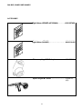
ESAB 230 MIG and 280 MIG Power Sources User manual
- Category
- Welding System
- Type
- User manual
This manual is also suitable for

200 MIG, 230 MIG and 280 MIG
Power Sources
Form No: 0558007453 03 / 2007
Instruction Manual
Installation, Operation and Service

These INSTRUCTIONS are for experienced operators. If you are not fully familiar with the principles of opera-
tion and safe practices for arc welding and cutting equipment, we urge you to read our booklet, "Precautions
and Safe Practices for Arc Welding, Cutting, and Gouging," Form 52-529. Do NOT permit untrained persons to
install, operate, or maintain this equipment. Do NOT attempt to install or operate this equipment until you
have read and fully understand these instructions. If you do not fully understand these instructions, contact
your supplier for further information. Be sure to read the Safety Precautions before installing or operating
this equipment.
Be sure this information reaches the operator.
You can get extra copies through Your supplier.
USER RESPONSIBILITY
This equipment will perform in conformity with the description thereof contained in this manual and
accompanying labels and/or inserts when installed, operated, maintained and repaired in accordance
with the instructions provided. This equipment must be checked periodically. Malfunctioning or poorly
maintained equipment should not be used. Parts that are broken, missing, worn, distorted or contami-
nated should be replaced immediately. Should such repair or replacement become necessary, the manu-
facturer recommends that a telephone or written request for service advice be made to the Authorized
Distributor from whom it was purchased.
This equipment or any of its parts should not be altered without the prior written approval of the manu-
facturer. The user of this equipment shall have the sole responsibility for any malfunction which results
from improper use, faulty maintenance, damage, improper repair or alteration by anyone other than the
manufacturer or a service facility designated by the manufacturer.
CAUTION

TABLE OF CONTENTS
1 DIRECTIVE 4. . . . . . . . . . . . . . . . . . . . . . . . . . . . . . . . . . . . . . . . . . . . . . . . . . . . . . . .
2 SAFETY 4. . . . . . . . . . . . . . . . . . . . . . . . . . . . . . . . . . . . . . . . . . . . . . . . . . . . . . . . . . .
3 INTRODUCTION 6. . . . . . . . . . . . . . . . . . . . . . . . . . . . . . . . . . . . . . . . . . . . . . . . . . .
3.1 Equipment 6. . . . . . . . . . . . . . . . . . . . . . . . . . . . . . . . . . . . . . . . . . . . . . . . . . . . . . . . . . . . . . . .
4 TECHNICAL DATA 6. . . . . . . . . . . . . . . . . . . . . . . . . . . . . . . . . . . . . . . . . . . . . . . . .
5 INSTALLATION 8. . . . . . . . . . . . . . . . . . . . . . . . . . . . . . . . . . . . . . . . . . . . . . . . . . . .
5.1 Placing 8. . . . . . . . . . . . . . . . . . . . . . . . . . . . . . . . . . . . . . . . . . . . . . . . . . . . . . . . . . . . . . . . . . .
5.2 Assembly of components 8. . . . . . . . . . . . . . . . . . . . . . . . . . . . . . . . . . . . . . . . . . . . . . . . . . .
5.3 Electrical installation 9. . . . . . . . . . . . . . . . . . . . . . . . . . . . . . . . . . . . . . . . . . . . . . . . . . . . . . .
5.4 Mains power supply 10. . . . . . . . . . . . . . . . . . . . . . . . . . . . . . . . . . . . . . . . . . . . . . . . . . . . . . . .
6 OPERATION 11. . . . . . . . . . . . . . . . . . . . . . . . . . . . . . . . . . . . . . . . . . . . . . . . . . . . . . .
6.1 Connection and control devices 11. . . . . . . . . . . . . . . . . . . . . . . . . . . . . . . . . . . . . . . . . . . . .
6.2 Functions explanation 12. . . . . . . . . . . . . . . . . . . . . . . . . . . . . . . . . . . . . . . . . . . . . . . . . . . . . .
6.3 MIG process set--up guide 12. . . . . . . . . . . . . . . . . . . . . . . . . . . . . . . . . . . . . . . . . . . . . . . . . .
7 MAINTENANCE 16. . . . . . . . . . . . . . . . . . . . . . . . . . . . . . . . . . . . . . . . . . . . . . . . . . . .
7.1 Inspection and cleaning 16. . . . . . . . . . . . . . . . . . . . . . . . . . . . . . . . . . . . . . . . . . . . . . . . . . . .
8 FAULT TRACING 17. . . . . . . . . . . . . . . . . . . . . . . . . . . . . . . . . . . . . . . . . . . . . . . . . . .
9 ORDERING OF SPARE PARTS 17. . . . . . . . . . . . . . . . . . . . . . . . . . . . . . . . . . . . . .
DIAGRAM 33. . . . . . . . . . . . . . . . . . . . . . . . . . . . . . . . . . . . . . . . . . . . . . . . . . . . . . . . . . . .
WEAR COMPONENTS 38. . . . . . . . . . . . . . . . . . . . . . . . . . . . . . . . . . . . . . . . . . . . . . . . .
ACCESSORIES 39. . . . . . . . . . . . . . . . . . . . . . . . . . . . . . . . . . . . . . . . . . . . . . . . . . . . . . .
4
5
17
17
19
21
21
21
22
23
25
25
26
26
31
31
33
35
37
42
43
1
2
3
4
5
6
7

4
DIRECTIVE
DECLARATION OF CONFORMITY
ESAB Welding Equipment AB, S--695 81 Laxå, Sweden, gives its unreserved guarantee that welding
power source Migmaster 173/203/253 from serial number 421/402/429 complies with standard IEC/
EN 60974--1, in accordance with the requirements of directive (73/23/EEC) and addendum
(93/68/EEC) and with standard EN 60974--10 in accordance with the requirements of directive
(89/336/EEC) and addendum (93/68/EEC).
--------------------------------------------------------------------------------------------------------------------------------------
Henry Selenius
Vice President
ESAB Welding Equipment AB
695 81 LAXÅ
SWEDEN Tel: + 46 584 81000 Fax: + 46 584 411924
Laxå 16.11.2004

5
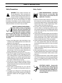
SAFETY PRECAUTIONS
Safety Precautions
Safety - English
WARNING: These Safety Precautions are
for your protection. They summarize pre-
cautionary information from the references
listed in Additional Safety Information sec-
tion. Before performing any installation or operating
procedures, be sure to read and follow the safety
precautions listed below as well as all other manuals,
material safety data sheets, labels, etc. Failure to observe
Safety Precautions can result in injury or death.
PROTECT YOURSELF AND OTHERS --
Some welding, cutting, and gouging
processes are noisy and require ear
protection. The arc, like the sun, emits
ultraviolet (UV) and other radiation
and can injure skin and eyes. Hot metal can cause
burns. Training in the proper use of the processes
and equipment is essential to prevent accidents.
Therefore:
1. Always wear safety glasses with side shields in any
work area, even if welding helmets, face shields, and
goggles are also required.
2. Use a face shield tted with the correct lter and
cover plates to protect your eyes, face, neck, and
ears from sparks and rays of the arc when operat-
ing or observing operations. Warn bystanders not
to watch the arc and not to expose themselves to
the rays of the electric-arc or hot metal.
3. Wear ameproof gauntlet type gloves, heavy long-
sleeve shirt, cuess trousers, high-topped shoes,
and a welding helmet or cap for hair protection, to
protect against arc rays and hot sparks or hot metal.
A ameproof apron may also be desirable as protec-
tion against radiated heat and sparks.
4. Hot sparks or metal can lodge in rolled up sleeves,
trouser cus, or pockets. Sleeves and collars should
be kept buttoned, and open pockets eliminated from
the front of clothing.
5. Protect other personnel from arc rays and hot
sparks with a suitable non-ammable partition or
curtains.
6. Use goggles over safety glasses when chipping slag
or grinding. Chipped slag may be hot and can y far.
Bystanders should also wear goggles over safety
glasses.
FIRES AND EXPLOSIONS -- Heat from
ames and arcs can start res. Hot
slag or sparks can also cause res and
explosions. Therefore:
1. Remove all combustible materials well away from
the work area or cover the materials with a protec-
tive non-ammable covering. Combustible materials
include wood, cloth, sawdust, liquid and gas fuels,
solvents, paints and coatings, paper, etc.
2. Hot sparks or hot metal can fall through cracks or
crevices in oors or wall openings and cause a hid-
den smoldering re or res on the oor below. Make
certain that such openings are protected from hot
sparks and metal.“
3. Do not weld, cut or perform other hot work until the
workpiece has been completely cleaned so that there
are no substances on the workpiece which might
produce ammable or toxic vapors. Do not do hot
work on closed containers. They may explode.
4. Have re extinguishing equipment handy for instant
use, such as a garden hose, water pail, sand bucket,
or portable re extinguisher. Be sure you are trained
in its use.
5. Do not use equipment beyond its ratings. For ex-
ample, overloaded welding cable can overheat and
create a re hazard.
6. After completing operations, inspect the work area
to make certain there are no hot sparks or hot metal
which could cause a later re. Use re watchers when
necessary.
7. For additional information, refer to NFPA Standard
51B, "Fire Prevention in Use of Cutting and Welding
Processes", available from the National Fire Protec-
tion Association, Batterymarch Park, Quincy, MA
02269.
ELECTRICAL SHOCK -- Contact with
live electrical parts and ground can
cause severe injury or death. DO NOT
use AC welding current in damp areas,
if movement is conned, or if there is
danger of falling.

6
SAFETY PRECAUTIONS
1. Be sure the power source frame (chassis) is con-
nected to the ground system of the input power.
2. Connect the workpiece to a good electrical
ground.
3. Connect the work cable to the workpiece. A poor
or missing connection can expose you or others
to a fatal shock.
4. Use well-maintained equipment. Replace worn or
damaged cables.
5. Keep everything dry, including clothing, work
area, cables, torch/electrode holder, and power
source.
6. Make sure that all parts of your body are insulated
from work and from ground.
7. Do not stand directly on metal or the earth while
working in tight quarters or a damp area; stand
on dry boards or an insulating platform and wear
rubber-soled shoes.
8. Put on dry, hole-free gloves before turning on the
power.
9. Turn o the power before removing your gloves.
10. Refer to ANSI/ASC Standard Z49.1 (listed on
next page) for specic grounding recommenda-
tions. Do not mistake the work lead for a ground
cable.
ELECTRIC AND MAGNETIC FIELDS
— May be dangerous. Electric cur-
rent owing through any conduc-
tor causes localized Electric and
Magnetic Fields (EMF). Welding and
cutting current creates EMF around welding cables
and welding machines. Therefore:
1. Welders having pacemakers should consult their
physician before welding. EMF may interfere with
some pacemakers.
2. Exposure to EMF may have other health eects which
are unknown.
3. Welders should use the following procedures to
minimize exposure to EMF:
A. Route the electrode and work cables together.
Secure them with tape when possible.
B. Never coil the torch or work cable around your
body.
C. Do not place your body between the torch and
work cables. Route cables on the same side of
your body.
D. Connect the work cable to the workpiece as close
as possible to the area being welded.
E. Keep welding power source and cables as far
away from your body as possible.
FUMES AND GASES -- Fumes and
gases, can cause discomfort or harm,
particularly in conned spaces. Do
not breathe fumes and gases. Shield-
ing gases can cause asphyxiation.
Therefore:
1. Always provide adequate ventilation in the work area
by natural or mechanical means. Do not weld, cut, or
gouge on materials such as galvanized steel, stain-
less steel, copper, zinc, lead, beryllium, or cadmium
unless positive mechanical ventilation is provided.
Do not breathe fumes from these materials.
2. Do not operate near degreasing and spraying opera-
tions. The heat or arc rays can react with chlorinated
hydrocarbon vapors to form phosgene, a highly
toxic gas, and other irritant gases.
3. If you develop momentary eye, nose, or throat ir-
ritation while operating, this is an indication that
ventilation is not adequate. Stop work and take
necessary steps to improve ventilation in the work
area. Do not continue to operate if physical discom-
fort persists.
4. Refer to ANSI/ASC Standard Z49.1 (see listing below)
for specic ventilation recommendations.

7
SAFETY PRECAUTIONS
5. WARNING: This product, when used for welding
or cutting, produces fumes or gases
which contain chemicals known to
the State of California to cause birth
defects and, in some cases, cancer.
(California Health & Safety Code
§25249.5 et seq.)
CYLINDER HANDLING -- Cylinders,
if mishandled, can rupture and vio-
lently release gas. Sudden rupture
of cylinder, valve, or relief device can
injure or kill. Therefore:
1. Use the proper gas for the process and use the
proper pressure reducing regulator designed to
operate from the compressed gas cylinder. Do not
use adaptors. Maintain hoses and ttings in good
condition. Follow manufacturer's operating instruc-
tions for mounting regulator to a compressed gas
cylinder.
2. Always secure cylinders in an upright position by
chain or strap to suitable hand trucks, undercar-
riages, benches, walls, post, or racks. Never secure
cylinders to work tables or xtures where they may
become part of an electrical circuit.
3. When not in use, keep cylinder valves closed. Have
valve protection cap in place if regulator is not con-
nected. Secure and move cylinders by using suitable
hand trucks. Avoid rough handling of cylinders.
4. Locate cylinders away from heat, sparks, and ames.
Never strike an arc on a cylinder.
5. For additional information, refer to CGA Standard P-1,
"Precautions for Safe Handling of Compressed Gases
in Cylinders", which is available from Compressed
Gas Association, 1235 Jeerson Davis Highway,
Arlington, VA 22202.
EQUIPMENT MAINTENANCE -- Faulty or
improperly maintained equipment can
cause injury or death. Therefore:
1. Always have qualied personnel perform the instal
-
lation, troubleshooting, and maintenance work.
Do not perform any electrical work unless you are
qualied to perform such work.
2. Before performing any maintenance work inside a
power source, disconnect the power source from
the incoming electrical power.
3. Maintain cables, grounding wire, connections, power
cord, and power supply in safe working order. Do
not operate any equipment in faulty condition.
4. Do not abuse any equipment or accessories. Keep
equipment away from heat sources such as furnaces,
wet conditions such as water puddles, oil or grease,
corrosive atmospheres and inclement weather.
5. Keep all safety devices and cabinet covers in position
and in good repair.
6. Use equipment only for its intended purpose. Do
not modify it in any manner.
ADDITIONAL SAFETY INFORMATION -- For
more information on safe practices for
electric arc welding and cutting equip-
ment, ask your supplier for a copy of
"Precautions and Safe Practices for Arc
Welding, Cutting and Gouging", Form
52-529.
The following publications, which are available from
the American Welding Society, 550 N.W. LeJuene Road,
Miami, FL 33126, are recommended to you:
1. ANSI/ASC Z49.1 - "Safety in Welding and Cutting"
2. AWS C5.1 - "Recommended Practices for Plasma Arc
Welding"
3. AWS C5.2 - "Recommended Practices for Plasma Arc
Cutting"
4. AWS C5.3 - "Recommended Practices for Air Carbon
Arc Gouging and Cutting"

8
SAFETY PRECAUTIONS
5. AWS C5.5 - "Recommended Practices for Gas Tung-
sten Arc Welding“
6. AWS C5.6 - "Recommended Practices for Gas Metal
Arc Welding"“
7. AWS SP - "Safe Practices" - Reprint, Welding Hand-
book.
8. ANSI/AWS F4.1, "Recommended Safe Practices for
Welding and Cutting of Containers That Have Held
Hazardous Substances."
MEANING OF SYMBOLS - As used
throughout this manual: Means Atten-
tion! Be Alert! Your safety is involved.
Means immediate hazards which,
if not avoided, will result in im-
mediate, serious personal injury
or loss of life.
Means potential hazards which
could result in personal injury or
loss of life.
Means hazards which could result
in minor personal injury.
Page is loading ...
Page is loading ...
Page is loading ...
Page is loading ...
Page is loading ...
Page is loading ...
Page is loading ...
Page is loading ...

17
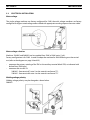
1.0 INTRODUCTION
200 MIG, 230 MIG and 280 MIG are step controlled power sources in a compact design, intended for
welding with solid steel, stainless steel or aluminium wire as well as ux-cored wire with or without
shielding gas.
200 MIG, 230 MIG and 280 MIG are equipped with facilities for connection of the MIG ”spool-on” gun
torch (type: MT-250SG).
Prest-O-Lite accessories for the product can be found on Page 43.
1.1 EQUIPMENT
The power source is supplied with:
Welding gun
Return cable 3m with return clamp
Shelf for gas cylinder
Instruction manual
•
•
•
•
SECTION 1 INTRODUCTION
Page is loading ...

19
SECTION 2 TECHNICAL DATA
-- 6 --
MM1725e
3 INTRODUCTION
Migmaster 173/203/253 are step controlled power sources in a compact design, intended for welding
with solid steel, stainless steel or aluminium wire as well as flux--cored wire with or without shielding
gas.
Machines MM 203 / 253 are equipped with facilities for connection of the MIG ”spool--on” gun torch
(type: MT--250SG).
ESAB’s accessories for the product can be found on page 39.
3.1 Equipment
The power source is supplied with:
� Welding gun
� Return cable 3m with return clamp
� Shelf for gas cylinder
� Instruction manual
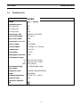
4 TECHNICAL DATA
Migmaster 173
Voltage 230V, 1∼ 50/60Hz
Permissible load at
100% duty cycle
76A
60 % duty cycle 98A
20 % duty cycle 170A
Setting range (DC) 30A/15.5V--170A/18.5V
Open circuit voltage 19.5--35.0V
Open circuit power 160W
Power factor at max load 0,90
Control voltage 42V, 50/60Hz
Wire feed speed 40--670ipm (1.0--17m/min)
Burnback time 0.02--0.25s
Spot welding 0.2--2.5s
Welding gun connection EURO
Wire dimension range
Fe
Al
FCW
.023--.030” (0.6--0.8mm)
.035--.040” (0.9--1.0mm)
.030” (0.8mm)
Max diameter/weight
of wire bobin
12” (300mm)/33lb (15kg)
Dimensions lxwxh 33x16x28” (860x420x730mm)
Weight 130lb (59kg)
Operating temperature 14÷104F (--10 ÷ +40
o
C)
Enclosure class IP 23
Application classifica-
tion
GB
2.0 TECHNICAL DATA
200 MIG

20
SECTION 2 TECHNICAL DATA
-- 7 --
MM1725e
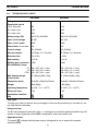
Migmaster 203 Migmaster 253
Voltage 230V, 1∼ 50/60Hz 230V, 1∼ 50/60Hz
Permissible load at
100% duty cycle
90A 110A
60 % duty cycle 115A 140A
20 % duty cycle 200A 250A
Setting range (DC) 30A/15.5V--200A/22V 40A/16.0V--250A/23V
Open circuit voltage 18--38V 19.5--43V
Open circuit power 140W 200W
Power factor at max load 0.83 0.92
Control voltage 42V, 50/60Hz 42V, 50/60Hz
Wire feed speed 40--670ipm (1.0--17m/min) 75--748ipm (1.9--19m/min)
Burnback time 0.02--0.25s 0--0.25s
Spot welding 0.2--2.5s 0.2--2.5s
Welding gun connection EURO EURO
Wire dimension range
Fe
Al
FCW
.023--.045” (0.6--1.1mm)
.035--.040” (0.9--1.0mm)
.030--.045” (0.8--1.1mm)
.023--.045” (0.6--1.1mm)
.040--3/64” (1.0--1.2mm)
.030--.045” (0.8--1.1mm)
Max diameter/weight
of wire bobin
12” (300mm)/33lb (15kg) 12” (300mm)/33lb (15kg)
Dimensions lxwxh 33x16x28” (860x420x730mm) 33x16x28” (860x420x730mm)
Weight 150lb (68kg) 216lb (98kg)
Operating temperature 14÷104F (--10 ÷ +40
o
C) 14÷104F (--10 ÷ +40
o
C)
Enclosure class IP 23 IP 23
Application classifica-
tion
Duty cycle
The duty cycle refers to the time as a percentage of a ten--minute period that you can weld at a cer-
tain load without overloading.
Enclosure class
The IP code indicates the enclosure class, i. e. the degree of protection against penetration by solid
objects or water. Equipment marked IP23 is designed for indoor and outdoor use.
Application class
The symbol indicates that the power source is designed for use in areas with increased
electrical hazard.
GB
2.0 TECHNICAL DATA CON'T.
230 MIG 280 MIG

21
SECTION 3 INSTALLATION
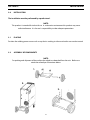
3.0 INSTALLATION
3.1 PLACING
3.2 ASSEMBLY OF COMPONENTS
The installation must be performed by a professional.
Position the welding power source such a way that its cooling air inlets and outlets are not obstructed.
NOTE:
For packing and shipment of the machine the wheels are detached from the unit. Before use
attach the wheels per illustrations below.
-- 8 --
MM1725e
5 INSTALLATION
The installation must be executed by a professional.
WARNING!
This product is intended for industrial use. In a domestic environment this product may cause radio
interference. It is the user’s responsibility to take adequate precautions.
5.1 Placing
Position the welding power source such way that its cooling air inlets and outlets are
not obstructed.
5.2 Assembly of components
For packing and shipment of the machine the wheels are detached from the unit.
Before use attach the wheels according to instruction.
WARNING!
1.
3.
2.
GB
NOTE:
This product is intended for industrial use. In a domestic environment this product may cause
radio interference. It is the user's responsibility to take adequate precautions.

22
SECTION 3 INSTALLATION
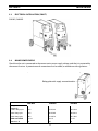
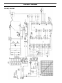
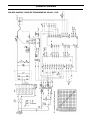
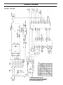
3.3 ELECTRICAL INSTALLATION
Mains voltage
The single voltage machines are factory-congured for 230V, the multi voltage machines are factory
congured for highest rated voltage and are tted with appropriate marking tape on the mains cable.
Mains voltage selection
Machines 230 MIG and 280 MIG can be supplied from 230V or 208V mains (1 ph.).
Factory conguration is for 230V. In order to adapt the machine for 208V following must be carried
out (refer to the diagrams on page 38 and 39):
reconnect the primary winding of the TM1 at the auxiliary terminal block XTM, as indicated with
dashed lines (208V taps),
reconnect the wire No 10:
280 MIG - from terminal 7 onto 5 on the control transformer TC1,
230 MIG - from terminal 6 onto 4 on the control transformer TC1.
•
•
Welding voltage polarity
Welding voltage polarity may be changed as shown below.
200 MIG

23
SECTION 3 INSTALLATION
3.3 ELECTRICAL INSTALLATION CON'T.
Check that the unit is connected to the correct mains power supply voltage, and that it is protected by
the correct fuse size. A protective earth connection must be made, in accordance with regulations.
3.4 MAINS POWER SUPPLY
-- 10 --
MM1725e
Migmaster 203/253
5.4 Mains power supply
Check that the unit is connected to the correct mains power supply voltage, and that it is protected by
the correct fuse size. A protective earth connection must be made, in accordance with regulations.
Rating plate with supply connection data
Migmaster 173 Migmaster 203 Migmaster 253
Voltage 230V, 1∼ 50/60Hz 208/230V, 1∼ 50/60Hz 208/230V, 1∼ 50/60Hz
Current A
at 100% duty cycle
10.5 15.5/14.0 18.6/16.8
at 60% duty cycle 14.5 20.5/18.5 25.9/23.4
at 20% duty cycle 28.0 41.0/37.0 53.1/48.0
Cable area AWG 3 x 10 3 x 10 3 x 10
Fuse slow A 16 25 35
GB
200 MIG 280 MIG230 MIG
230 MIG, 280 MIG
Page is loading ...

25
SECTION 4 OPERATION
4.0 OPERATION
General safety regulations for the handling of the equipment can be found on
Page 5. Read thoroughly before you start using the equipment!
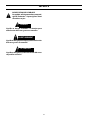
ROTATING PARTS CAN CAUSE INJURY, TAKE GREAT
CARE.
TIPPING RISK! THERE IS A RISK OF TIPPING WHILE
TRANSPORTING AND OPERATING IF THE WELDING
MACHINE LEANS MORE THAN 10
. IN THAT CASE
APPROPRIATE SECURING HAS TO BE PROVIDED!
CAUTION
-- 11 --
MM1725e
6 OPERATION
General safety regulations for the handling of the equipment can be found on
page 4. Read through before you start using the equipment!
WARNING!
Rotating parts can cause injury, take great care.
WARNING -- TIPPING RISK!
There is a risk of tipping while transportation and operation, if the welding machine leans
more than 10
o
. In that case appropriate securing has to be provided !
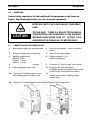
6.1 Connection and control devices
1 Mains supply switch with indicating lamp 6 Knob for spot welding -- ON/OFF and time
setting
2 Orange indicating lamp, overheating 7 Knob for wire speed setting
3 Welding voltage switch
Migmaster 173: 8 steps
Migmaster 203: 12 steps
Migmaster 253: 12 steps
8 Digital instrument -- V/A,
(option,see page 39)
4 EURO -- connector for welding gun 9 Connector for ”spool--on gun” (wire control)
5 Return cable with clamp, fixed 10 Knob for burn--back time setting.
In M 253 located in wire feeder compartment,
in M 170/200 located on control board.
5a Connector [--] for welding gun or return
cable (welding polarity change--over)
11 ”Electrode” cable with plug, connected to the
welding gun connector (welding polarity
change--over)
5b Connector [+] for welding gun or return cable (welding polarity change--over)
GB
-- 11 --
MM1725e
6 OPERATION
General safety regulations for the handling of the equipment can be found on
page 4. Read through before you start using the equipment!
WARNING!
Rotating parts can cause injury, take great care.
WARNING -- TIPPING RISK!
There is a risk of tipping while transportation and operation, if the welding machine leans
more than 10
o
. In that case appropriate securing has to be provided !
6.1 Connection and control devices
1 Mains supply switch with indicating lamp 6 Knob for spot welding -- ON/OFF and time
setting
2 Orange indicating lamp, overheating 7 Knob for wire speed setting
3 Welding voltage switch
Migmaster 173: 8 steps
Migmaster 203: 12 steps
Migmaster 253: 12 steps
8 Digital instrument -- V/A,
(option,see page 39)
4 EURO -- connector for welding gun 9 Connector for ”spool--on gun” (wire control)
5 Return cable with clamp, fixed 10 Knob for burn--back time setting.
In M 253 located in wire feeder compartment,
in M 170/200 located on control board.
5a Connector [--] for welding gun or return
cable (welding polarity change--over)
11 ”Electrode” cable with plug, connected to the
welding gun connector (welding polarity
change--over)
5b Connector [+] for welding gun or return cable (welding polarity change--over)
GB
4.1 CONNECTION AND CONTROL DEVICES
200 MIG: 8 steps
230 MIG: 12 steps
280 MIG: 12 steps
In 280 MIG located in wire feeder compartment,
in 200/230 MIG located on control board.

26
SECTION 4 OPERATION
4.2 FUNCTIONS EXPLANATION
4.2.1 SWITCHINGON AND OVERHEATING PROTECTION
4.2.2 OPERATION
4.3 MIG PROCESS SETUP GUIDE
When machine is switched on with the illuminated switch [1], its lamp is on. If the machine is not over-
heated (lamp [2] is o) it is ready to work. If the internal temperature during welding becomes too high,
the welding is interrupted and disabled. This state is indicated by permanent lighting of the orange
indicating lamp [2] on the front of the unit. It resets automatically when the temperature falls down.
Operator can manually select and set welding parameters as follows:
required welding voltage ( and thus welding current) with knob [3]
appropriate wire feed speed with knob [7]
burn-back time: for 280 MIG with potentiometer [10] located in the wire feeder compartment, for
200/230 MIG with trim potentiometer located on the control board inside the machine
spot welding, activated by turning the knob [6] clockwise, spot welding time increases while turning
the knob [6] clockwise; set knob [6] in the left utmost position in order to return to the continuous
welding.
If the welding gun is used, welding process starts after its trigger is pressed and the wire speed is con-
trolled with potentiometer [7] on the front panel.
If the spool-on gun is used, welding process starts after its trigger is pressed, the spool-on gun motor
starts and wire speed is controlled with the potentiometer in the spool-on gun grip.
Note: For spool-on gun current cable connection it is necessary to use the OKC ”T” adapter (see Acces-
sories on Page 43).
Machines optionally may be tted with V/A digital instrument [8] (with ”hold” function i.e. memorizing
of the last values of welding voltage and current, see Page 43).
•
•
•
•
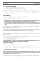
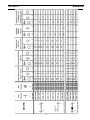
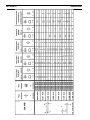
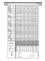
In the following tables, separately for each machine, recommended welding settings are shown, de-
pending on the joint type, workpiece thickness and ller wire diameter.
To set machine for welding:
nd the plate thickness (T) and type of joint,
nd the diameter (d) of the ller wire,
in the column corresponding to the appropriate material and shielding gas nd the suggested arc
voltage and wire feed setting; if spot welding nd recommended time setting,
set arc voltage selector [3], wire feed potentiometer [7], and (if necessary) the spot welding time [6]
according to values found in table.
NOTE: The given recommendations only serve as rough guide for the operator, optimal set-ups may dif-
fer from the ones in tables. It depends on mains voltage deviation, precision of the wire speed setting,
applied welding techniques, welding position, etc.
If needed, some corrections of the arc voltage and wire speed may be tried out for satisfactory results.
•
•
•
•
Page is loading ...
Page is loading ...
Page is loading ...
Page is loading ...

31
SECTION 5 MAINTENANCE
5.0 MAINTENANCE
5.1 INSPECTION AND CLEANING
Regular maintenance is important for safe, reliable operation.
NOTE:
Warranty from the supplier is void if the customer attempts any type repair work on the prod-
uct during the warranty period.
Check regularly that the power source is free from dirt.
The power source should be regularly blown clean using dry compressed air at reduced pressure. More
frequently in dirty environments. Otherwise the air inlet/outlet may become blocked and cause over-
heating.
Welding gun
Cleaning and replacement of the welding gun’s wear parts should take place at regular intervals in
order to achieve trouble-free wire feed. Blow the wire guide clean regularly and clean the contact
tip.
•
-- 16 --
MM1725e
7 MAINTENANCE
Regular maintenance is important for safe, reliable operation.
Note!
All guarantee undertakings from the supplier cease to apply if the customer himself
attempts any work in the product during the guarantee period in order to rectify any
faults.
7.1 Inspection and cleaning
Check regularly that the power source is free from dirt.
The power source should be regularly blown clean using dry compressed air at reduced
pressure. More frequently in dirty environments. Otherwise the air inlet/outlet may be-
come blocked and cause overheating.
Welding gun
� Cleaning and replacement of the welding gun’s wear parts should take place at
regular intervals in order to achieve trouble--free wire feed. Blow the wire guide
clean regularly and clean the contact tip.
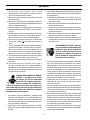
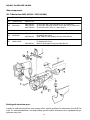
The brake hub
The hub is adjusted when delivered, if
readjustment is required, follow the instructions
below. Adjust the brake hub so that wire is slightly
slack when wire feed stops.
� Adjusting the braking torque:
� Turn the red handle to the locked position.
� Insert a screwdriver into the springs in the hub.
Turn the springs clockwise to reduce the braking torque
Turn the springs anticlockwise to increase the braking torque. NB: Turn both
springs through the same amount.
GB
The brake hub
Page is loading ...

33
SECTION 6 FAULT TRACING
-- 17 --
MM1725e
8 FAULT TRACING
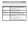
Try these recommended checks and inspections before sending for an authorised service technican.
Type of fault
Actions
No arc � Check that the mains power supply switch is turned on.
� Check that the welding current supply and return cables are
correctly connected.
� Check that correct current value is set.
Welding current is interrupted
during welding
� Check whether the thermal overload trip has operated
(indicated by the orange lamp on the front).
� Check the main power supply fuses.
Thermal overload trips
operate frequently
� Check to see whether the air inlets/outlets are clogged.
� Make sure that you are not exceeding the rated data for the
power source (i.e. that the unit is not being overloaded).
Poor welding performance � Check that the welding current supply and return cables are
correctly connected.
� Check that the correct current value is set.
� Check that the correct welding wires are being used.
� Check the main power supply fuses.
� Check the wire feed unit -- if proper rolls are applied and
properly set the pressure of the wire feeder’s pressure rollers
9 ORDERING OF SPARE PARTS
Migmaster 173/203/253 is designed and tested in accordance with the international and
European standards IEC/EN 60974--1 and EN 60974--10. It is the obligation of the servi-
ce unit which has carried out the service or repair work to make sure that the product
still conforms to the said standard.
Spare parts may be ordered through your nearest ESAB dealer, see the last page of
this publication.
GB

34
SECTION 6 FAULT TRACING

35
SECTION 7 ORDERING OF SPARE PARTS
NOTE:
200/230/280 MIG is designed and tested in accordance with the international and Euro-
pean standards IEC/EN 60974-1 and EN 60974-10. It is the obligation of the service unit
which has carried out the service or repair work to make sure that the product still con-
forms to the said standard.
Spare parts may be ordered through your nearest Prest-O-Lite dealer, see the last page of this publica-
tion.
7.0 ORDERING OF SPARE PARTS
Page is loading ...
Page is loading ...
Page is loading ...
Page is loading ...
Page is loading ...
Page is loading ...
Page is loading ...
Page is loading ...
Page is loading ...
Page is loading ...
Page is loading ...
Page is loading ...
Page is loading ...
-
 1
1
-
 2
2
-
 3
3
-
 4
4
-
 5
5
-
 6
6
-
 7
7
-
 8
8
-
 9
9
-
 10
10
-
 11
11
-
 12
12
-
 13
13
-
 14
14
-
 15
15
-
 16
16
-
 17
17
-
 18
18
-
 19
19
-
 20
20
-
 21
21
-
 22
22
-
 23
23
-
 24
24
-
 25
25
-
 26
26
-
 27
27
-
 28
28
-
 29
29
-
 30
30
-
 31
31
-
 32
32
-
 33
33
-
 34
34
-
 35
35
-
 36
36
-
 37
37
-
 38
38
-
 39
39
-
 40
40
-
 41
41
-
 42
42
-
 43
43
-
 44
44
-
 45
45
-
 46
46
-
 47
47
-
 48
48


ESAB 230 MIG and 280 MIG Power Sources User manual
- Category
- Welding System
- Type
- User manual
- This manual is also suitable for
Ask a question and I''ll find the answer in the document
Finding information in a document is now easier with AI
in other languages
Other documents
-
Crossfire HG252 Owner's manual
-
-
-
 Fronius TT 400 Operating instructions
-
Watchguard XTM 800 Series Quick start guide
-
-
-
-
-
