Tripp Lite SmartOnline ® SUT 3-Phase UPS System 20/30/40/60kVA Owner's manual
- Type
- Owner's manual

1
Owner’s Manual
SmartOnline
®
SUT
3-Phase UPS System
20/30/40/60kVA
Models: SUT20K, SUT30K, SUT40K, SUT60K
AG-01F9, AG-01FA, AG-01FB, AG-01FC
Input: 120/127V (Ph-N)
208/220V (Ph-Ph), 3ph 4-Wire + PE
1111 W. 35th Street, Chicago, IL 60609 USA • www.tripplite.com/support
Copyright © 2017 Tripp Lite. All rights reserved.
PROTECT YOUR INVESTMENT!
Register your product for quicker service and ultimate peace of mind.
You could also win an ISOBAR6ULTRA surge protector—a $100 value!
www.tripplite.com/warranty

2
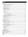
Table of Contents
1. Introduction ......................................................................................................................... 3
2. Important Safety Instructions ..............................................................................................4
2.1 Placement Warnings ......................................................................................................................................... 4
2.2 Connection Warnings ........................................................................................................................................ 4
2.3 Usage Warnings ................................................................................................................................................ 4
2.4 Storage Warnings ............................................................................................................................................. 5
2.5 Glossary of Symbols ......................................................................................................................................... 5
2.6 Standard Compliance ........................................................................................................................................ 6
3. Installation and Wiring .........................................................................................................6
3.1 Important Safety Warning ................................................................................................................................. 6
3.2 Transportation .................................................................................................................................................. 7
3.3 Delivery ............................................................................................................................................................ 7
3.4 Installation Environment ................................................................................................................................... 7
3.5 UPS Installation ................................................................................................................................................ 8
3.6 Wiring ............................................................................................................................................................ 10
3.6.1 Precautions Prior to Wiring ................................................................................................................... 10
3.6.2 Wiring Procedure .................................................................................................................................. 11
3.6.3 Parallel Units Wiring ............................................................................................................................. 14
3.7 External Battery Cabinet Connection Precautions ........................................................................................... 15
4. System Components ..........................................................................................................17
4.1 Appearance and Dimensions .......................................................................................................................... 17
4.2 Front View ...................................................................................................................................................... 17
4.3 Front View with Door Open .............................................................................................................................. 18
4.4 Control Panel ................................................................................................................................................. 19
4.5 Rear Panel ..................................................................................................................................................... 20
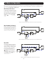
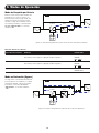
5. Operation Modes ............................................................................................................... 22
6. Communication Interfaces ................................................................................................25
7. Operation ...........................................................................................................................29
7.1 Connecting the UPS with Utility AC Power ....................................................................................................... 29
7.2 Turn On (Starting the Inverter) ......................................................................................................................... 29
7.3 Turn Off (UPS Shutdown) ................................................................................................................................. 29
7.4 Cold Start (Battery Start) Procedure ............................................................................................................... 29
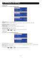
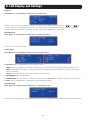
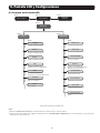
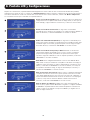
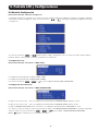
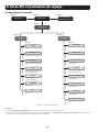
8. LCD Display and Settings ....................................................................................................30
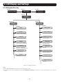
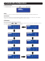
8.1 LCD Display Hierarchy .................................................................................................................................... 30
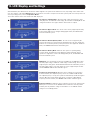
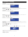
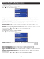
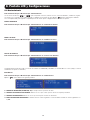
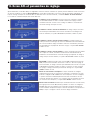
8.2 Setting Menu .................................................................................................................................................. 32
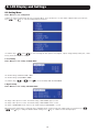
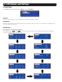
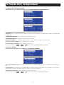
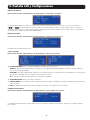
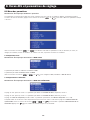
8.3 Parallel Screen .............................................................................................................................................. 35
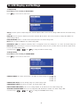
8.4 Main Menu ..................................................................................................................................................... 36
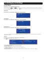
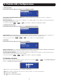
8.5 Measure ........................................................................................................................................................ 36
8.6 Maintenance .................................................................................................................................................. 37
9. Optional Accessories ........................................................................................................39
10. Maintenance ......................................................................................................................39
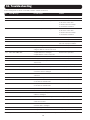
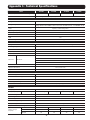
11. Troubleshooting .................................................................................................................40
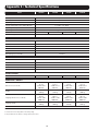
Appendix 1 : Technical Specifications .....................................................................................41
Appendix 2 : Warranty .............................................................................................................43
Español ................................................................................................................................... 44
Français ..................................................................................................................................87

3
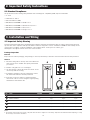
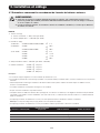
1. Introduction
Tripp Lite’s SmartOnline SUT Series Uninterruptible Power Supply (UPS) is a Voltage and Frequency Independent (VFI) true on-line, double
conversion 3-Phase UPS system. The UPS continuously conditions the incoming electrical power supply, eliminating power fluctuations
and interruptions that will otherwise damage sensitive electronic devices and cause system downtime.
The UPS applies the latest in DSP digital control technology and an output power factor up to unity. The efficiency of the UPS reaches
up to 94% in normal operation, and up to 98% in ECO mode, making it one of the most efficient UPS systems in its class. In addition
to supplying clean, reliable and uninterrupted power to sensitive electronic devices at all times, the SmartOnline SUT produces greater
power efficiency at a lower cost.
With four different rated power levels – 20kVA, 30kVA, 40kVA and 60kVA – and offering paralleling capability up to 4 units, the UPS
offers multiple capacity options to suit the load’s requirements and offers the following features:
• True on-line UPS. Highest level of UPS protection, fully regulating the incoming power supply and transferring immediately to battery in
the event of an extended mains failure to continuously support critical loads.
• All digital, high frequency modulation technology, which decreases operating volume, improves reliability and prolongs service life.
• Wide AC input voltage range minimizes frequent transfer from normal operation to battery mode, saving battery consumption and
prolonging battery life.
• High efficiency – lower losses reduce cooling costs and extend system lifespan.
• Unity output power factor – more actual power allows more equipment to be supported.
• Programmable LCD allows users to conveniently set parameters for the UPS system; key operating conditions are visible via LCD for
accurate, clear monitoring.
• Serial, USB and volt-free contact communication as standard; SNMP and MODBUS options for optimum configurability. Monitoring and
management of the UPS via Tripp Lite’s free PowerAlert
®
power management software. Download at www.tripplite.com/poweralert.
• Automatic fan detection indicates whether fans are operating normally; multi-stage fan speed control improves their reliability and
efficiency, reduces operating noise and prolongs the service life of the fans.
• Both boost and float charge are provided. The charge current is adjustable from 1A to 20A. Charging mode is linked to charging
current, maintaining the batteries at full charge capacity and extending battery life (float charge voltage: 163.2V DC; boost charge
voltage: 168V DC).
The SmartOnline SUT UPS is ideally designed for protecting critical electrical equipment for:
• Data centers
• Telecommunications
• Computer network systems
• Medical treatment equipment
• Monitoring systems
• Light industrial
• Financial institutions

4
2. Important Safety Instructions
SAVE THESE INSTRUCTIONS
This manual contains instructions and warnings that should be followed during the installation, operation and storage of
this product. Failure to heed these instructions and warnings may affect the product warranty.
2.1 Placement Warnings
Install the UPS in a well-ventilated indoor area, away from excess moisture, heat, dust, flammable gas or explosives. Leave adequate
space around all sides of the UPS for proper ventilation. Refer to 3.4 Installation Environment.
2.2 Connection Warnings
• The UPS must be well grounded due to a possible risk of current leakage.
• It is necessary to install protective devices and 4-pole contactors when the UPS is connected to the mains and bypass source.
For relevant information, refer to 3.6.1 Precautions Prior to Wiring.
• The protective devices connecting to the UPS must be installed near the UPS and must be easily accessible for operation.
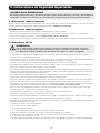
2.3 Usage Warnings
WARNING:
To avoid any hazardous conditions during UPS installation and/or maintenance, these tasks must be performed
only by an engineer authorized by Tripp Lite. Proper startup procedures must be followed in order for warranty to
be valid. Contact Tripp Lite for further information.
• This is a class-A product. In a domestic environment, this product may cause radio interference, in which case, the user is required to
take adequate measures.
• Use of this equipment in life support applications where failure of this equipment can reasonably be expected to cause the failure of
the life support equipment or to significantly affect its safety or effectiveness is not recommended.
• If the UPS needs to be connected to a motor load, it must be confirmed by qualified service personnel.
• The parallel UPS systems can connect with common batteries. Before paralleling batteries, please make sure the battery voltage
difference between each UPS is lower than 5V DC.
• The external vents and openings in the UPS are provided for ventilation. To ensure reliable operation of the UPS and to protect the UPS
from overheating, these vents and openings must not be blocked or covered. Do not insert any object into the vents and openings that
may hinder ventilation.
• In a low temperature environment (below 32°F/0°C), you must allow the UPS to adjust to room temperature for at least one hour
before using to avoid moisture condensing inside the UPS.
• Do not place beverage containers or other liquids on the UPS, battery cabinet or any other accessory associated with the UPS.
• The risk of dangerous high voltage is possible when the batteries are still connected to the UPS even though the UPS is disconnected
from the mains. Do not forget to disconnect battery cables to completely cut off the battery source. For more information about battery
maintenance, refer to 4.3 Front View with Door Open.
• All maintenance services must be performed by qualified service personnel. To avoid risk of high-voltage electrical shock, do not open
or remove the UPS cover.
• Do not open or mutilate the battery or batteries. The released electrolyte is harmful to the skin and eyes and may be toxic.
• Do not dispose of the battery or batteries in a fire. The batteries may explode.
• The batteries contain chemical substances that may jeopardize or pollute our environment. Please contact the supplier shown on the
batteries to properly dispose of the batteries.
• A battery can present a risk of electric shock and high short-circuit current. The following precautions should be observed before
replacement of batteries:
1. Remove watches, rings or other metal objects.
2. Use tools with insulated handles.
3. Wear insulating gloves and boots.
4. Do not lay tools or metal parts on the top of batteries.
5. Disconnect the charging source prior to connecting or disconnecting the batteries’ terminals.
• Contact qualified service personnel if either of the following events occur:
1. Liquid is poured or splashed on the UPS.
2. The UPS does not run normally after instructions in this Owner’s Manual are carefully observed.

5
2. Important Safety Instructions
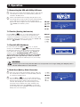
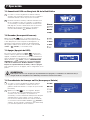
2.4 Storage Warnings
Prior to Installation
If the UPS needs to be stored prior to installation, it should be placed in a dry area. The allowable storage temperature is 5~104°F
(-15~40°C).
After Usage
Press the OFF key (
OFF
) once and the LCD will appear with the below screen. To turn off the UPS, press the DOWN key ( ).
Make sure the UPS is in bypass mode, disconnect the UPS from the utility power, open the internal battery fuse holders (refer to
4.3 Front View with Door Open), remove all equipment from the UPS and store the UPS in a dry and well-ventilated area at a
temperature between 5~104°F (-15~40°C). Idle batteries must be fully recharged approximately every three months if the UPS needs to
be stored for an extended period of time. The charging time must not be less than 24 hours each time.
?
Transfer to Bypass Mode
YES( ) NO( )
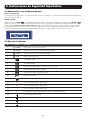
2.5 Glossary of Symbols
No. Symbol Description
1
NORMAL
On-line mode LED indicator: green
2
BATTERY
Battery mode LED indicator: yellow
3
BYPASS
Bypass mode LED indicator: yellow
4
FAULT
Fault LED indicator: red
5
ON
ON key
6
OFF
OFF key
7
ESC
Goes back to previous screen or cancels current selection
8 Moves down/Decreases number
9 Moves up/Increases number
10 Confirms selection
11
EPO
EPO key
12 R R phase of AC input/UPS output
13 S S phase of AC input/UPS output
14 T T phase of AC input/UPS output
15 N Input neutral line/Output neutral line/Battery neutral line
16 For UPS grounding
17 For critical load grounding/For external battery cabinet grounding
18 Positive battery terminal
19 Negative battery terminal

6
2. Important Safety Instructions
3. Installation and Wiring
2.6 Standard Compliance
This product meets the following safety standards and electromagnetic compatibility (EMC) inspection standards:
• UL 1778
• CSA C22.2 No. 107.3
• FCC Part 15 Class A (EMC)
• GB17626-2 / IEC 61000-4-2 (ESD) Level 4
• GB17626-3 / IEC 61000-4-3 (Radiated Field) Level 3
• GB17626-4 / IEC 61000-4-4 (EFT) Level 4
• GB17626-5 / IEC 61000-4-5 (Surge) Level 4
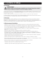
3.1 Important Safety Warning
Read this manual thoroughly before undertaking any installation and wiring. An authorized Tripp Lite engineer must perform the start-
up of the UPS and a completed start-up form must be returned to Tripp Lite in order to activate the SmartOnline SUT warranty. Please
contact your local supplier or [email protected] for further details. To find your local contact, go to
www.tripplite.com/support/contacts and click on ‘Service Centers’.
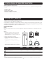
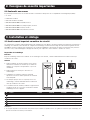
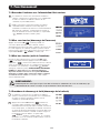
Package Inspection
External
Inspect the UPS exterior packaging. If any damage is observed, immediately contact the dealer from whom the UPS was purchased.
Internal
(Male) (Female) (Female) (Female)
1 2 3
4 5
1. Check the rating label on the top of the UPS cabinet and
make sure the device number and capacity match what
you ordered.
2. Examine if any parts are loose or damaged.
3. The UPS package contains the items listed below. Please
check if any items are missing.
4. If anything is damaged or missing, immediately contact
the dealer from whom the UPS was purchased.
5. If the UPS needs to be returned, carefully repack the
UPS and all of the accessories using the original packing
material that came with the unit.
No. Item SUT20K SUT30K
SUT40K SUT60K
1
UPS (with internal batteries) 1 pc. 1 pc.
1 pc. 1 pc.
2
Owner's Manual 1 pc. 1 pc.
1 pc. 1 pc.
3
Test Card 1 pc. 1 pc.
1 pc. 1 pc.
4
RS-232 Cable (Male/Female) 1 pc. 1 pc.
1 pc. 1 pc.
5
Parallel Cable (Female/Female) 1 pc. 1 pc.
1 pc. 1 pc.
Notes:
1. The balance supports have been locked on the pallet when the UPS is shipped out of the factory. Keep them well maintained after unpacking, as it may
be necessary to use them for installation.

7
3. Installation and Wiring
3.2 Transportation
WARNING
The UPS is packed on a pallet suitable for handling with a forklift. If using a forklift or other equipment to move
the UPS, ensure its load bearing is sufficient to support the total packing weight of the UPS.
The UPS is fixed on the pallet with four balance supports. Do not discard the balance supports, as they may be required for installation
(see section 3.5 UPS Installation). When removing them, pay attention to the movement of the casters to avoid accidents.
The UPS cabinet may be pushed forward or backwards only; it may not be moved sideways.
If moving the UPS over long distance, use appropriate equipment such as a forklift; do not move the UPS cabinet using its attached
casters over long distances, move the UPS cabinet in its original packaging until at the final destination site.
3.3 Delivery
Inspect the packaging materials and UPS cabinet carefully upon delivery. Do not install a damaged UPS, connect it to a battery or to
the utility. The packing box of the UPS is equipped with an anti-tilt device. Confirm the device does not indicate any shock or excess tilt
during transit. If the device indicates there has been excessive shock or tilt, do not install and contact your local Tripp Lite representative.
3.4 Installation Environment
• The UPS is designed for indoor use only. Do not place or install the UPS in an outdoor area.
• When moving the UPS to its installation site, ensure all corridors, doors, gates, elevators, floors, etc. are able to accommodate and
bear the combined weight of the UPS system, any associated battery cabinets and all handling equipment. See Appendix 1 for UPS
combined weights.
• The installation site should have a dedicated AC circuit available, compatible with the UPS system’s input requirements. See
Appendix 1 for input specifications.
• Ensure the installation area has sufficient space for maintenance and ventilation of the UPS system.
• Maintain the installation area’s temperature below 86°F (30°C) and the humidity level below 90%. The highest operating altitude is
6500 ft. (2000 m) above sea level. Please consider the derating values when operating the UPS over 3300 ft. (1000 m); refer to
Appendix 1. The optimum operating temperature for the batteries is between 68~77° (20~25°C).
• The UPS should be located in an environment with clean air and adequate ventilation to maintain the ambient temperature within the
UPS operating range.
• The UPS is air-cooled with the aid of internal fans. Do not cover the ventilation openings of the UPS system.
• Install the UPS in an area in which the walls, floors and ceilings are constructed with fireproof materials. The UPS is suitable for
mounting on concrete or other non-combustible surfaces only.
• Install a CO
2
or dry powder extinguisher in the installation area.
• Ensure the installation area is adequately sized for maintenance and ventilation:
o Maintain a clearance of 3 ft. (1 m) from the front of the UPS.
o Maintain a clearance of 1.67 ft. (50 cm) from the rear and both sides of the UPS.

8
3. Installation and Wiring
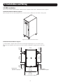
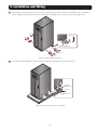
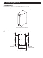
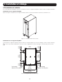
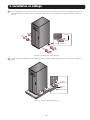
3.5 UPS Installation
There are two installation methods. One is with the balance supports and the other is without the balance supports.
Installation without the Balance Supports
After moving the UPS to its final installation area, use the levelers to stabilize the UPS cabinet on the ground.
(Figure 3-1: Stabilize the UPS with Levelers)
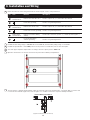
Installation with the Balance Supports
To reinstall balance supports removed from the UPS during the unpacking process, follow these steps:
1
Once the installation area has been selected, follow the mounting hole diagram below to drill holes.
(621.6 mm)
24.5 in.
(561.6 mm)
22.1 in.
(80 mm)
3.1in.
(80 mm)
3.1in.
(80 mm)
3.1in.
(80 mm)
3.1in.
(420 mm)
16.5 in.
(420 mm)
16.5 in.
Mounting Hole
(Diameter:ø12 mm)8 pcs.
Mounting Hole
(Diameter:ø6.5 mm)8 pcs
(Front)
(Back)
(Figure 3-2: Mounting Hole Diagram)

9
3. Installation and Wiring
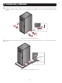
2
Place the UPS over the drilled holes, use the levelers to stabilize the UPS on the ground and use the M6 screws to reinstall the
balance supports (that were removed from the UPS during the unpacking process) on the UPS. Refer to the figure below.
M6 Screw x 8
Balance Support x 4
(Figure 3-3: Balance Support Installation)
3
Use four user-supplied M8 bolts to fix the four balance supports on the ground to avoid UPS movement.
Ground
M8 Bolts x 4
Balance
Support x 4
(Figure 3-4: Fix the Balance Supports on the Ground)

10
3. Installation and Wiring
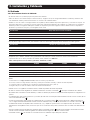
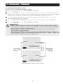
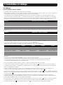
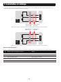
3.6 Wiring
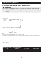
3.6.1 Precautions Prior to Wiring
• The wiring must be performed by qualified professional personnel.
• Before wiring or making any electrical connection, make sure the power supplied to the input and output of the UPS is completely cut
off and the internal battery connectors are disconnected.
• When connecting the UPS to the utility AC power and bypass source, protective devices and 4-pole connectors must be installed. The
protective devices and 4-pole contactors must use approved components that meet safety certifications. Please refer to the following
table for suggested protective devices. For the installation of the protective devices and 4-pole contactors, see Figures 3-10~3-18.
UPS System Recommended Protective Device
SUT20K D-Curve 75A circuit breaker
SUT30K D-Curve 125A circuit breaker
SUT40K
D-Curve 150A circuit breaker
SUT60K
D-Curve 225A circuit breaker
• When connecting the critical loads to the UPS, a listed certified breaker must be installed between them. Refer to the table below
UPS System Recommended 3-Pole Breaker
SUT20K C-Curve 75A circuit breaker
SUT30K C-Curve 125A circuit breaker
SUT40K
C-Curve 150A circuit breaker
SUT60K
C-Curve 225A circuit breaker
• Check that the size, diameter, phase and polarity of each cable connecting to the UPS is correct. For the specifications of input/output
cables and circuit breakers, refer to Table 3-1.
Table 3-1: Specifications of Input/Output Cables and Circuit Breakers
SUT20K SUT30K SUT40K SUT60K
AC Input Cable* 2 AWG (25 mm
2
) 1/0 AWG (50 mm
2
) 3/0 AWG (95 mm
2
) 250 kcmil (120 mm
2
)
Output Cable* 2 AWG (25 mm
2
) 1/0 AWG (50 mm
2
) 3/0 AWG (95 mm
2
) 250 kcmil (120 mm
2
)
Battery Input Cable* 1 AWG (35 mm
2
) 1/0 AWG (50 mm
2
) 3/0 AWG (95 mm
2
) 250 kcmil (120 mm
2
)
Tightening Torque 130 in. lb. (14.7 N·m) 130 in. lb. (14.7 N·m) 130 in. lb. (14.7 N·m) 130 in. lb. (14.7 N·m)
Input Breaker 75A (3-pole x 1) 125A (3-pole x 1) 150A (3-pole x 1) 225A (3-pole x 1)
* Use only copper wire rated to 194°F (90°C) or higher
Notes:
1. In accordance with local electrical codes, install a suitable conduit and bushing.
2. Please refer to national and local electrical codes for acceptable non-fuse breakers and cable size.
3. Cables with PVC material and with temperature resistance up to 201°F (105°C) are suggested.
4. Make sure that the input/output cables are locked tightly.
• When connecting with the external battery cabinet, confirm the polarity. Do not reverse the polarity.
• The grounding cable of the external battery cabinet must be connected to the ( ) terminal of the battery terminal block.
• Installer should consider the maximum current and wiring gauge that may be required for future expansion of parallel configurations.
• The input of the UPS must be a Y connection, and the neutral line (N) must be connected to avoid UPS failure. Do not connect the
neutral line (N) of the UPS with the ground terminal ( ).
• If there is a floating voltage between the input power’s neutral (N) and the ground ( ) and you require that the VNG of the UPS
should be zero, it is suggested an installation transformer be installed in front of the UPS input side and the UPS neutral (N) be
connected with the ground ( ).
• The utility AC power must be three phases (R/S/T) and meet the specifications on the UPS rating label. When connecting the utility
input power to the UPS, make sure it is in positive phase sequence (clockwise phase rotation).
• Connect the external battery cabinet’s grounding terminal to the grounding terminal ( ) of the UPS system’s battery terminal block.
Do not connect the grounding terminal of the external battery cabinet to any other grounding system.
• The ground terminal ( ) of the UPS must be grounded. Use ring-type terminal for wiring.

11
3. Installation and Wiring
WARNING:
1. Incorrect wiring will lead to severe electric shock and damage to the UPS.
2. The UPS will not work normally if the input power's neutral (N) is not firmly connected or is not connected to
the AC Input Block's neutral (N) terminal.
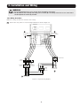
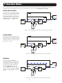
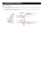
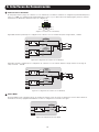
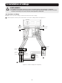
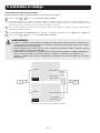
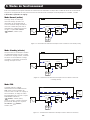
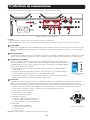
3.6.2 Wiring Procedure
Note: Prior to wiring, first read 3.6.1 Precautions Prior to Wiring.
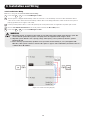
1
Remove the cover plate to access the wiring terminal block shown in Figure 3-5.
CS
N R S T
N
R S T
4-Pole
Contactor
Protective
Device
CS:
Contactor
Solenoid
N R
S T
Output Breaker:
R S T
N
Connects to the
main AC source
N R
S T
Manual
Bypass
Breaker
R S T
N
For grounding
the Critical Loads
Connect to the
Critical Loads
For grounding
the UPS
(Figure 3-5: Single Unit Wiring Diagram)
1
2
3
4

12
2
Ensure the functions of the wiring terminal block shown in Figure 3-5 are clearly understood.
No. Item Function Description
1
AC Input
Terminal Block
Connects the main AC source Includes 3-phase (R, S, T) and neutral (N) terminals
2
For the UPS grounding Includes one grounding terminal
3
UPS Output
Terminal Block
Connects the critical loads Includes 3-phase (R, S, T) and neutral (N) terminals
4
For the critical loads’ grounding Includes one grounding terminal
5
Battery Input
Terminal Block
Connects an external battery
cabinet
Includes three terminals, positive (+), neutral (N) and negative (-)
6
For an external battery
cabinet’s grounding
Includes one grounding terminal
3
Confirm the UPS rating voltage is 120/208V AC or 127/220V AC, and the battery rating voltage is ±144V DC.
4
Confirm the input breaker is in the OFF position. For the position of each breaker, refer to unit’s front panel.
5
Select the proper input and output cables according to the UPS capacity (refer to Table 3-1).
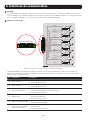
6
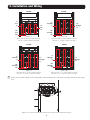
Open the UPS front door to unscrew and remove the panel labeled “Battery Compartment”.
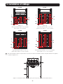
7
The UPS system is shipped with the battery cables disconnected. Remove the insulation tape covering the BAT(+) red wires and
reconnect to the terminals (Figure 3-6). Refer to Figures 3-7~3-10 for each model’s respective battery installation.
Internal Battery Installation
(Figure 3-6: Battery Cable Connection)
3. Installation and Wiring

13
8
Connect optional external battery to the external battery cabinet terminal block located at the lower right of the unit (refer to Figure
3-11).
3. Installation and Wiring
(Figure 3-7)
First connect the -1 and -2 cables on the left,
then the +1 and +2 cables on the right.
–1
and
–2
–1
through
–3
–1
through
–3
–1
through
–4
N1
and
N2
N1
through
N3
N1
through
N3
N1
through
N4
+1
and
+2
+1
through
+3
+1
through
+3
+1
through
+4
(Figure 3-8)
First connect the -1, -2 and -3 cables on the left,
then the +1, +2 and +3 cables on the right.
(Figure 3-9)
First connect the -1, -2 and -3 cables on the left,
then the +1, +2 and +3 cables on the right.
(Figure 3-10)
First connect the -1, -2, -3 and -4 cables on the left,
then the +1, +2, +3 and +4 cables on the right.
(Figure 3-11: Connect an external battery [optional] to the external battery cabinet terminal block.)
5
6
SUT20K
SUT60K
SUT30K
SUT40K

14
3. Installation and Wiring
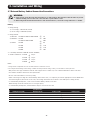
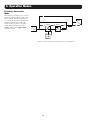
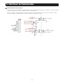
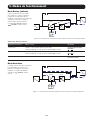
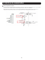
3.6.3 Parallel Units Wiring
Note: Prior to wiring, first read 3.6.1 Precautions Prior to Wiring.
1
Follow steps
1
~
5
in section 3.6.2 Wiring Procedure.
2
The UPS system is shipped with the battery cables disconnected. Locate the battery connection cables behind the labeled
connector door in the cabinet. Connect the battery cabinet cables to the wiring terminal block and ensure the UPS system is
properly grounded (refer to Figures 3-6~3-10).
3
Use the provided parallel cable to connect the parallel ports on the parallel units. See Figure 6-1 for parallel port location.
4
Refer to 6. Communication Interfaces to set the parallel switch in the ON or OFF position.
5
Follow steps
7
~
8
in section 3.6.2 Wiring Procedure.
WARNING:
1. When UPS systems are paralleled, the length of each unit’s input cables/output cables must be equal. This
ensures that the parallel UPS systems can equally share the equipment loads in bypass mode.
2. Only UPS systems with the same capacity, voltage and frequency can be paralleled; otherwise, parallel
functions will fail.
3. Before start-up of parallel units, qualified service personnel should set ID (0, 1, 2 or 3) through the LCD.
Otherwise, UPS systems cannot be started. If the symbol ‘!’ appears after an ID number, it indicates there is a
conflict between ID numbers.
UPS 1
UPS 2
UPS 4
I/P
LOAD
AC Input
AC Input
AC Input
UPS Output
UPS Output
UPS Output
Parallel Port
Parallel Port
Parallel Port
Parallel Port
Parallel Cable
3Ø4W 3Ø4W
Parallel Cable
(Figure 3-12: Parallel Units Wiring Diagram)

15
3. Installation and Wiring
3.7 External Battery Cabinet Connection Precautions
WARNING:
1. Connect loads to the UPS only after the batteries are fully charged. This guarantees that the UPS can provide
sufficient backup power to the loads connected when a power failure occurs.
2. When using both the UPS internal batteries and external batteries, ensure the voltage difference is <5V DC.
Battery
1. Charge Voltage
1) Float voltage: ±163.2V DC (default)
2) Boost voltage: ±168V DC (default)
2. Charge Current
1) Minimum: SUT20K/SUT30K/SUT40K/SUT60K
g
1A
2) Maximum: SUT20K
g
10A
SUT30K/SUT40K/SUT60K
g
20A
3) Default: SUT20K
g
5A
SUT30K
g
7.5A
SUT40K
g
7.5A
SUT60K
g
10A
3. Low Battery Shutdown: 120V DC (default: 120V DC)
4. Number of Batteries: SUT20K
g
48 pcs.
SUT30K
g
72 pcs.
SUT40K
g
72 pcs.
SUT60K
g
96 pcs.
Notes:
1. Charge current is adjustable from 1A to the 20A maximum in increments of 0.5A.
2. To modify the default charge current setting or default low battery shutdown setting, contact your local dealer or service personnel.
• Only use the same type of batteries from the same supplier. Never combine old, new or different Ah batteries at the same time.
• The number of batteries must meet UPS requirements.
• Do not connect the batteries in reverse polarity.
• When connecting a non-Tripp Lite external battery cabinet to the UPS, it is compulsory to install an appropriate non-fuse DC breaker
and fast-acting fuses (when short-circuit occurs, the melting current must be 5~6 times of the battery fuse’s rating current).
• To extend battery backup time, connect several external battery cabinets to the UPS.
Note: Recharge time will be extended; take note of charger capacity.
• To extend battery backup time, external batteries may be connected to the UPS.
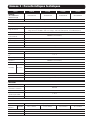
Rating Power (kVA)
Circuit Breaker
Rating Current Battery Cable Battery Fuse
20 250V AC / 75A 1 AWG (35 mm
2
) 660V DC / 80A
30 250V AC / 125A 1/0 AWG (50 mm
2
) 660V DC / 125A
40 250V AC / 150A 3/0 AWG (95 mm
2
) 660V DC / 150A
60 250V AC / 250A 250 kcmil (120 mm
2
) 660V DC / 250A

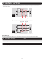
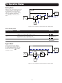
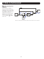
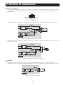
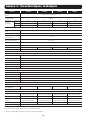
16
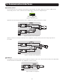
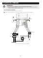
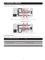
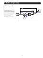
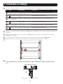
• The breaker must be a 3-pole DC breaker with a 250V DC rating per pole. Follow Figure 3-13 or Figure 3-14 between the UPS
external battery cabinet.
External
Battery
Cabinet
-
N
+
-
N
+
UPS
3-pole Non-fuse
DC Breaker
Fast-acting
Fuses
(Figure 3-13: A 3-pole Non-fuse DC Breaker and Fast-acting Fuses Installation I)
External
Battery
Cabinet
3-pole Non-fuse
DC Breaker
Fast-acting
Fuses
UPS
-
N
+
-
N
+
(Figure 3-14: A 3-pole Non-fuse DC Breaker and Fast-acting Fuses Installation II)
3. Installation and Wiring
Battery Status Alarm
When the UPS system’s batteries experience one of the problems shown below, the system will sound the following alarms:
No. External Battery Cabinet Status Alarm
1 Battery Test Fail Sounds once every 2 seconds
2 Battery Low Warning Sounds once every 0.5 second
3 Battery Low Shutdown Long beep (5 seconds)
4 Battery Over Charge Sounds once every 2 seconds
5 Battery Missing Sounds once every 2 seconds

17
4. System Components
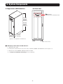
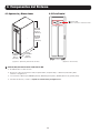
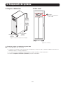
4.1 Appearance and Dimensions
SUT20K,
SUT30K
53.15 in.
(1350 mm)
SUT40K,
SUT60K
69.3 in.
(1760 mm)
All models
31.5 in.
(800 mm)
All models
20.5 in.
(521 mm)
(Figure 4-1: UPS Appearance and Dimensions)
1
LCD Display, Control Panel and LED Indicators
1. LCD displays UPS status.
2. Control panel includes ESC, move-up, move-down, confirmation, ON/OFF and EPO buttons (refer to Figure 4-7).
3. LED indicators include NORMAL, BATTERY, BYPASS and FAULT.
4. See Chapter 8. LCD Display and Settings for more information.
4.2 Front View
LCD Display,
Control Panel and LED Indicators
1
(Figure 4-2: Front View)

18
4. System Components
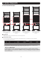
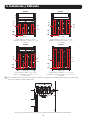
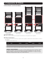
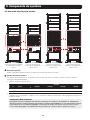
4.3 Front View with Door Open
2
3
2
3
2
Input Breaker
Controls the UPS system’s main input switch and is used for safety protection.
3
Internal Battery Cabinet
The four UPS models have different contents inside the internal battery cabinet. See the table below for more information.
1. The internal battery cabinet includes:
No. Item
Quantity
SUT20K SUT30K SUT40K SUT60K
1 Internal Batteries 48 72 72 96
2 Battery Tray 12 18 18 24
2. The internal batteries, battery trays and battery cables shown in the above table have already been configured at factory.
Only qualified service personnel should perform battery installation, wiring and connection.
START UP and COMMISSIONING
An authorized Tripp Lite engineer must perform the start-up of the UPS and a completed start-up form must be
returned to Tripp Lite in order to activate the SmartOnline SUT-Series warranty. Please contact your local supplier or
intlser[email protected] for further details. To find your local contact, go to www.tripplite.com/support/contacts and
click on ‘Service Centers’.
(Figure 4-3: SUT20K Front
View with Door Open and
Battery Compartment Panel
Removed.)
(Figure 4-4: SUT30K Front
View with Door Open and
Battery Compartment Panel
Removed.)
(Figure 4-5: SUT40K Front
View with Door Open and
Battery Compartment Panel
Removed.)
(Figure 4-6: SUT60K Front
View with Door Open and
Battery Compartment Panel
Removed.)

19
4. System Components
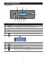
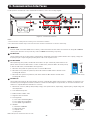
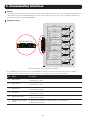
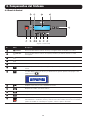
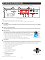
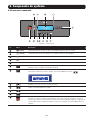
4.4 Control Panel
ESC
7
1
2
5
6
3
8
4
12
9
10
11
(Figure 4-7: Front Panel)
No. Item Description
1
NORMAL
UPS is operating in on-line mode and the utility AC power is normal.
2
BATTERY
UPS is operating in battery mode and the external batteries are discharging.
3
BYPASS
UPS is operating in bypass mode.
4
FAULT
UPS has abnormalities.
5
LCD Display
Displays UPS operating status and relevant monitoring data.
6
ON
ON key: Press this key for 3~4 seconds and release it after hearing a beep to start up the UPS.
7
OFF
OFF key: Press this key once and the LCD shows the following screen. To
shut down the UPS, press
the DOWN
key ( ).
?
Transfer to Bypass Mode
YES( ) NO( )
8
Confirms selection and accesses menu screen.
9
Moves up/Increases number.
10
Moves down/Decreases number.
11
ESC
Goes back to previous screen or cancels current selection.
12
EPO
When an emergency event occurs, press the EPO key for more than one second to shut down the
rectifier, inverter and output of the UPS immediately. To reset, disconnect the EPO key and push the
unit’s OFF button for 3 seconds, then push the unit’s ON button.

20
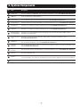
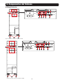
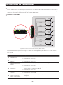
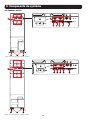
4.5 Rear Panel
4. System Components
(Figure 4-9: SUT40K, SUT60K Rear Panel)
(Figure 4-8: SUT20K, SUT30K Rear Panel)
1
2
3
7 8 9 10 11
12
14
13
14
4 5 6
1
2
3
7 8 9 10 11
12
14 13 14
4 5 6
Page is loading ...
Page is loading ...
Page is loading ...
Page is loading ...
Page is loading ...
Page is loading ...
Page is loading ...
Page is loading ...
Page is loading ...
Page is loading ...
Page is loading ...
Page is loading ...
Page is loading ...
Page is loading ...
Page is loading ...
Page is loading ...
Page is loading ...
Page is loading ...
Page is loading ...
Page is loading ...
Page is loading ...
Page is loading ...
Page is loading ...
Page is loading ...
Page is loading ...
Page is loading ...
Page is loading ...
Page is loading ...
Page is loading ...
Page is loading ...
Page is loading ...
Page is loading ...
Page is loading ...
Page is loading ...
Page is loading ...
Page is loading ...
Page is loading ...
Page is loading ...
Page is loading ...
Page is loading ...
Page is loading ...
Page is loading ...
Page is loading ...
Page is loading ...
Page is loading ...
Page is loading ...
Page is loading ...
Page is loading ...
Page is loading ...
Page is loading ...
Page is loading ...
Page is loading ...
Page is loading ...
Page is loading ...
Page is loading ...
Page is loading ...
Page is loading ...
Page is loading ...
Page is loading ...
Page is loading ...
Page is loading ...
Page is loading ...
Page is loading ...
Page is loading ...
Page is loading ...
Page is loading ...
Page is loading ...
Page is loading ...
Page is loading ...
Page is loading ...
Page is loading ...
Page is loading ...
Page is loading ...
Page is loading ...
Page is loading ...
Page is loading ...
Page is loading ...
Page is loading ...
Page is loading ...
Page is loading ...
Page is loading ...
Page is loading ...
Page is loading ...
Page is loading ...
Page is loading ...
Page is loading ...
Page is loading ...
Page is loading ...
Page is loading ...
Page is loading ...
Page is loading ...
Page is loading ...
Page is loading ...
Page is loading ...
Page is loading ...
Page is loading ...
Page is loading ...
Page is loading ...
Page is loading ...
Page is loading ...
Page is loading ...
Page is loading ...
Page is loading ...
Page is loading ...
Page is loading ...
Page is loading ...
Page is loading ...
Page is loading ...
Page is loading ...
Page is loading ...
Page is loading ...
Page is loading ...
-
 1
1
-
 2
2
-
 3
3
-
 4
4
-
 5
5
-
 6
6
-
 7
7
-
 8
8
-
 9
9
-
 10
10
-
 11
11
-
 12
12
-
 13
13
-
 14
14
-
 15
15
-
 16
16
-
 17
17
-
 18
18
-
 19
19
-
 20
20
-
 21
21
-
 22
22
-
 23
23
-
 24
24
-
 25
25
-
 26
26
-
 27
27
-
 28
28
-
 29
29
-
 30
30
-
 31
31
-
 32
32
-
 33
33
-
 34
34
-
 35
35
-
 36
36
-
 37
37
-
 38
38
-
 39
39
-
 40
40
-
 41
41
-
 42
42
-
 43
43
-
 44
44
-
 45
45
-
 46
46
-
 47
47
-
 48
48
-
 49
49
-
 50
50
-
 51
51
-
 52
52
-
 53
53
-
 54
54
-
 55
55
-
 56
56
-
 57
57
-
 58
58
-
 59
59
-
 60
60
-
 61
61
-
 62
62
-
 63
63
-
 64
64
-
 65
65
-
 66
66
-
 67
67
-
 68
68
-
 69
69
-
 70
70
-
 71
71
-
 72
72
-
 73
73
-
 74
74
-
 75
75
-
 76
76
-
 77
77
-
 78
78
-
 79
79
-
 80
80
-
 81
81
-
 82
82
-
 83
83
-
 84
84
-
 85
85
-
 86
86
-
 87
87
-
 88
88
-
 89
89
-
 90
90
-
 91
91
-
 92
92
-
 93
93
-
 94
94
-
 95
95
-
 96
96
-
 97
97
-
 98
98
-
 99
99
-
 100
100
-
 101
101
-
 102
102
-
 103
103
-
 104
104
-
 105
105
-
 106
106
-
 107
107
-
 108
108
-
 109
109
-
 110
110
-
 111
111
-
 112
112
-
 113
113
-
 114
114
-
 115
115
-
 116
116
-
 117
117
-
 118
118
-
 119
119
-
 120
120
-
 121
121
-
 122
122
-
 123
123
-
 124
124
-
 125
125
-
 126
126
-
 127
127
-
 128
128
-
 129
129
-
 130
130
-
 131
131
-
 132
132


Tripp Lite SmartOnline ® SUT 3-Phase UPS System 20/30/40/60kVA Owner's manual
- Type
- Owner's manual
Ask a question and I''ll find the answer in the document
Finding information in a document is now easier with AI
in other languages
Related papers
-
Tripp Lite SUTX20K & SUTX40K Owner's manual
-
-
-
Tripp Lite SmartOnline SVT20KX Owner's manual
-
-
-
-
-
-
Other documents
-
 POTEK P750W User manual
-
 OPTI-UPS DS1000D User manual
-
Legrand Online-UPS-1-3KVA-I-00884 Owner's manual
-
Sunforce 200Watt POWER INVERTER User manual
-
Legrand Line-Interactive-UPS-1-3KVA-I-00886 Owner's manual
-
BlueWalker PowerWalker VFI 1000RM LCD User manual
-
BlueWalker PowerWalker VFI 1000 LCD Specification
-
Steren INV-400 Owner's manual
-
BlueWalker PowerWalker VFI 3000 LCD/UK Specification
-
 OPTI-UPS DS120KD33 User manual


