
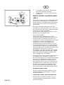
RANSOMES
®
Safety And Operation Manual / List Of Parts
Manuel De Securite & De Fonctionnement / Liste De Pieces
Veiligheids & Bedienings Handleiding / Onderdelenlijst
Sicherheits Und Bedienungs Anleitung / Ersatzteilliste
Manuale D’istruzioni Per I’uso E La Sicurezza / Lista Dei Componenti
Manual Del Operario / Lista De Piezas
Instruktionsbok / Reservdelslista
Operatørinstruktioner / Reservdeliste
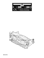
Fairway and T-Plex Cutting Units
Series: NR, NS, SC, SA, SB, SG, SH, SK, SL, SM, SU, SV, SX, TB, TW, TX, TY, UM, UN, UP,
UQ, UR,
RANSOMES
AVVERTENZA: Questa macchina può causare gravi infortuni
se viene utilizzata in modo errato. Prima di accingersi ad
approntare, usare, mettere a punto o eseguire la
manutenzione di questa macchina, coloro che la utilizzano
ed i responsabili della manutenzione devono essere
addestrati all’impiego della macchina, devono essere informati
dei pericoli, e devono leggere l’intero manuale.
GB
Part No. 23877G (rev.5)(RJ 100 072000)
F NL D I
WARNHINWEIS: Wenn diese Maschine nicht ordnungsgemäß
verwendet wird, können ernsthafte Verletzungen verursacht
werden. Personen, die diese Maschine verwenden und
warten, müssen in ihrer richtigen Verwendung ausgebildet
sein, auf die Gefahren aufmerksam gemacht worden sein
und die Anleitung ganz gelesen haben, bevor sie versuchen,
die Maschine aufzustellen, zu bedienen, einzustellen oder
zu warten.
WAARSCHUWING: Bij verkeerd gebruik kan deze machine
ernstig lichamelijk letsel veroorzaken. Degenen die de ma-
chine gebruiken en onderhouden moeten worden getraind
in het juiste gebruik ervan, worden gewaarschuwd voor de
gevaren ervan en behoren de volledige handleiding
aandachtig te lezen alvorens de machine bedrijfs-klaar te
maken, te bedienen, af te stellen en/of te onderhouden.
AVERTISSEMENT : Risque de blessures graves en cas
d’utilisation incorrecte de la machine. Les opérateurs et le
personnel d’entretien doivent être formés et conscients des
dangers encourus. Ils doivent lire avec attention le manuel
avant d’essayer de monter, d’utiliser, de régler ou maintenir
la machine.
WARNING: If incorrectly used this machine can cause se-
vere injury. Those who use and maintain this machine should
be trained in its proper use, warned of its dangers and should
read the entire manual before attempting to set up, operate,
adjust or service the machine.
DK S E
ADVERTENCIA: Si se usa de forma incorrecta esta
máquina puede causar graves lesiones. Cualquier per-
sona que use y mantenga esta máquina deberá estar
entrenado en su uso correcto, instruido de sus peligro y
deberá leer el manual completamente antes de tratar de
instalar, operar, ajustar o revisar la máquina.
VARNING: Om denna maskin används på fel sätt kan
den orsaka svåra personskador. De som använder och
underhåller denna maskin ska utbildas i hur den används
korrekt, vara varnade för de förekommande riskerna och
ska alltid läsa hela handboken innan någon form av
arbete utförs på eller med maskinen.
ADVARSEL: Denne maskine kan forårsage alvorlig
personskade, hvis den bruges forkert. Alle, der bruger
og vedligeholder denne maskine, skal være korrekt
uddannet til dette, skal advares om farerne og læse hele
instruktionsbogen, før maskinen forberedes, bruges,
justeres eller serviceres.
VAROITUS: Laitteen virheellinen käyttö voi aiheuttaa
vakavia vahinkoja. Laitteen käyttäjille ja huoltajille on
opetettava laitteen asianmukainen käyttö, heitä on
varoitettava mahdollisista vaaroista ja heidän on luettava
koko käyttöopas ennen laitteen valmistelua, käyttöä,
säätämistä ja huoltamista.

© 2000, Textron Inc. All Rights Reserved

GB-F-NL-1
IMPORTANT: This is a precision machine and the service obtained from it depends on the way it is operated
and maintained.
This operators manual should be regarded as part of the machine. Suppliers of both new and second-hand
machines are advised to retain documentary evidence that this manual was provided with the machine.
This machine is designed solely for use in customary grass cutting operations. Use in any other way is
considered as contrary to the intended use. Compliance with and strict adherence to the conditions of
operation, service and repair as specified by the manufacturer, also constitute essential elements of the
intended use.
Before attempting to operate this machine, ALL operators MUST read through this manual and make
themselves thoroughly conversant with Safety Instructions, controls, lubrication and maintenance.
Accident prevention regulations, all other generally recognized regulations on safety and occupational
medicine, and all road traffic regulations shall be observed at all times.
Any arbitrary modifications carried out on this machine may relieve the manufacturer of liability for
any resulting damage or injury.
BELANGRIJK: Dit is een precisie-machine en de kwaliteit van de werkzaamheden die hiermee kunnen
worden uitgevoerd, is afhankelijk van de manier waarop de maaimachine wordt bediend en onderhouden.
Dit bedienershandboek dient te worden gezien als een onderdeel van de machine. Leveranciers van zowel
nieuwe als tweedehands-machines worden geadviseerd om altijd documentair bewijsmateriaal beschikbaar
te hebben waaruit blijkt dat dit handboek bij de machine werd geleverd.
Deze machine werd uitsluitend ontworpen als een grasmaaimachine. Als de machine voor andere
doeleinden wordt gebruikt, dan zal dit worden geïnterpreteerd als een inbreuk op de
toepassingsmogelijkheden waarvoor de machine bestemd is. Het nakomen van en het zich houden aan de
bedrijfscondities, het onderhoud en de reparaties overeenkomstig de specificaties van de klant, zijn in feite
ook essentiële elementen van het bedoelde gebruik van de machine.
Voordat wordt getracht om deze machine te bedienen, dienen ALLE bedieners dit handboek goed te hebben
doorgelezen. Ook moeten zij geheel op de hoogte zijn van de veiligheidsinstructies, de bedieningsorganen,
de smering en het onderhoud.
Bepalingen voor de preventie van ongevallen, alle andere algemeen erkende bepalingen van toepassing op
veiligheid en de medische behandeling van bedrijfsrisico’s en alle bepalingen in de wegenverkeerswet,
mogen nooit worden overschreden.
Het is mogelijk dat door eventueel eigenmachtig aan de machine uitgevoerde modificaties, de fabrikant
wordt ontheven van verwondingen voortvloeiend uit eventuele beschadiging of verwondingen.
NL
IMPORTANT: Il s’agit d’une machine de précision et sa fiabilité dépend de la façon dont elle est utilisée et
entretenue.
Ce manuel d’instruction doit être considéré comme une partie de la machine. Il est conseillé aux
fournisseurs de machines neuves et d’occasion de conserver une preuve écrite attestant que ce manuel a
été fourni avec la machine.
Cette machine est uniquement conçue pour la tonte du gazon ordinaire. Son utilisation à toute autre fin est
considérée comme contraire à l’usage auquel la machine est destinée. La conformité et l’observation stricte
des conditions d’utilisation, de révision et de réparation, telles qu’elles sont spécifiées par le fabricant,
constituent également des éléments essentiels de l’usage auquel la machine est destinée.
Avant d’utiliser cette machine, TOUS les opérateurs DOIVENT lire attentivement ce manuel et se
familiariser avec les instructions de sécurité, les commandes, la lubrification et l’entretien.
Les réglementations de prévention d’accidents, toutes les autres réglementations reconnues de sécurité et
de médecine du travail, ainsi que les réglementations routières doivent toujours être observées.
Toute modification arbitraire effectuée sur cette machine dégage la responsabilité du fabricant quant aux
endommagements ou blessures résultant d’une telle modification.
GB
F
Page is loading ...

GB-F-NL-3
GB
NL
F
Contents: Page
Safety instructions ......................................................................................... 4
Specification .................................................................................................. 6
Fitting the unit to the machine ....................................................................... 8
Operating the unit .......................................................................................... 8
Lubrication ..................................................................................................... 10
Maintenance .................................................................................................. 12
Adjustments ................................................................................................... 14
End of season servicing................................................................................. 18
Guarantee ...................................................................................................... 20
Sales & service .............................................................................................. 21
List of Parts.................................................................................................... 25
Table des mattiéres Page
Consignes de sécurité .................................................................................... 5
Caractéristiques .............................................................................................. 7
Montage de l'unité sur la machine.................................................................. 9
Fonctionnement de l'unité .............................................................................. 9
Lubrification ....................................................................................................11
Entretien......................................................................................................... 13
Réglages ........................................................................................................ 15
Remisage....................................................................................................... 19
Garantie ......................................................................................................... 20
Liste de pièces ............................................................................................... 25
Inhoud: Pagina
Veiligheidsinstructies ..................................................................................... 5
Specificaties................................................................................................... 7
De eenheid op de machine monteren ........................................................... 9
De eenheid bedienen..................................................................................... 9
Smering.......................................................................................................... 11
Onderhoud ..................................................................................................... 13
Afstellingen .................................................................................................... 15
Onderhoud aan het eind van het seizoen...................................................... 19
Garantie ......................................................................................................... 20
Verkoop & Service ......................................................................................... 21
Onderdelenlijst............................................................................................... 23

GB-F-NL-4
GB
SAFETY INSTRUCTIONS
NOTE: Refer also to safety instructions in the
power unit operating instruction book.
OPERATING INSTRUCTIONS
Ensure that the instructions in this book are read and
fully understood.
No person should be allowed to operate these units
unless they are fully acquainted with all the controls and
the safety procedures.
BLOCKED CUTTING CYLINDERS
Release blockages with care. Keep all parts of the body
away from the cutting edges Beware of energy in the
drive system which can cause rotation when the blockage
is released.
Keep other people away from the cutting units, as
rotation of one cylinder can cause the others to rotate.
ADJUSTMENTS, LUBRICATION AND
MAINTENANCE
Read all the appropriate servicing instructions. Use
only replacement parts supplied by the original
manufacturer.
When adjusting the cutting cylinders take care not to get
hands and feet trapped when rotating cylinders Make
sure that other people are not touching any cutting unit,
as rotation of one cylinder may cause the others to
rotate.
GB
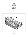
This safety symbol indicates important safety
messages in this manual. When you see this
symbol, be alert to the possibility of injury, carefully
read the message that follows, and inform other
operators.
NL
Door dit veiligheidssymbool worden belangrijke
veiligheidsmeldingen in dit handboek aangegeven.
Als u dit symbool ziet, wees u dan bewust van
fysieke risico’s. Altijd de bijbehorende instructies
goed lezen en ook andere bedieners op de hoogte
brengen.
F
Ce symbole de sécurité indique les messages de
sécurité importants figurant dans ce manuel. Lorsque
vous voyez ce symbole, soyez conscient des risques
de blessures, lisez attentivement le message qui suit
et informez tous les autres opérateurs.
Page is loading ...

GB-F-NL-6
GB
SPECIFICATION
CONSTRUCTION
Heavy duty welded pressed steel construction
CYLINDER:
Diameter: 165mm (6 1/2in)
Width of cut: 660mm (26in)
Number of knives: 7 and 11
Height of cut: 6mm - 38mm
(1/4in - 1 1/2in)
CUTTING CYLINDER TO BOTTOM BLOCK
ADJUSTMENT
Self locking notched hand micro adjusters. Each
notch giving 0.04mm (0.0015in) of movement.
HEIGHT OF CUT ADJUSTMENT
Front roll: Threaded roll carriage & locknuts.
Rear roll: Coarse adjustment: Three position
housing mounting.
Fine adjustment: Threaded roll
carriage & locknuts
REAR ROLL
Full width 75mm (3in) diameter plain roll running on
taper roller bearings with shaft seals and lubricators.
FRONT ROLL
Full width 75mm (3in) diameter grooved roll running
on taper roller bearings with shaft seals and
lubricators.
or
Full width 75mm (3in) diameter plain roll running on
taper roller bearings with shaft seals and lubricators.
BOTTOM BLOCK & BLADE
Blade replaceable, mounted onto welded steel
constructed bottom block.
TRANSMISSION
By hydraulic motor through cardan shaft to cutting
cylinder.
Page is loading ...

GB-F-NL-8
GB
Fitting the unit to the machine is described in the
power unit operating instruction book.
OPERATING THE UNIT
Read the Safety Instructions
Operating the unit is described in the power unit
operating instruction book.
Read the Safety Instructions
FITTING THE UNIT TO THE MACHINE
Page is loading ...

GB-F-NL-10
GB
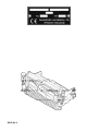
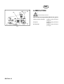
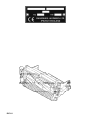
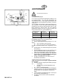
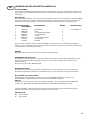
Fig.1
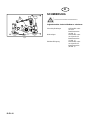
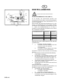
LUBRICATION
Read the Safety Instructions
Lubricate the following with Shell Retinax ‘A’ grease.
Cutting cylinder bearings weekly or every 25 hours.
(A Fig.1)
Unit pivot weekly or every 25 hours.
(B Fig.1)
Roll bearings weekly or every 25 hours.
(C Fig.1)
Page is loading ...

GB-F-NL-12
GB
MAINTENANCE
Read the Safety Instructions
Check all nuts and bolts every 75 hours
Lubrication of Direct Drive Hydraulic Motor
(Every 400 hours)
Lower all cutting units onto level ground. Before leaving
the driving position, stop the engine and make sure all
moving parts are stationary. Apply brakes and
disengage all drives. remove the starter key. The direct
drive hydraulic motor can be removed from the cutting
unit by removing the two screws and washers holding
the motor to the bearing housing. Carefully withdraw
the motor from the bearing housing, it is important not
to contaminate the motor shaft or internal splines of
the cutting cylinder. If for any reason they are
contaminated, they should be cleaned by degreasing.
Liberally lubricate the motor and cylinder splines with
Shell S7222 grease (Textron Part no. MBE3927)
before reassembling.
Page is loading ...

GB-F-NL-14
GB
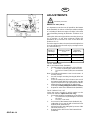
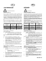
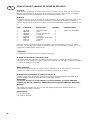
Fig.2
ADJUSTMENTS
Read Safety Instructions
HEIGHT OF CUT (FIG.2)
It is important to set the rear roll parallel to the bottom
blade (bedknife) in order to achieve the minimum height
of cut setting for the three ranges of height, in the three
sets of mounting housing (D) bolt holes. Positions 'A','B'
&'C'.
Setting the minimum height with the mounting housings
(D) in position 'A' will allow minimum height and
parallelism to be achieved in each of the other two
positions 'B' & 'C'.
Once the range has been chosen the actual height of cut
is set by adjusting the front roll only by carriage screws
(F) and locknuts (J).
Height of minimum height maximum
cut range of cut height of cut
Holes 'A' 6.0mm(1/4in) 23.0mm(29/32in)
Holes 'B' 13.8mm(9/16in) 30.0mm(1 3/16in)
Holes 'C' 21.7mm(27/32in) 38.0mm(1 1/2in)
TO SET REAR ROLL
with a new bottom blade (bedknife)
1. Set the height of cut setting bar (G)as follows:
a. Screw X to 6mm(1/4in) under the head.
b. Screw Y to 5.2mm (7/32in) to screw thread
tip.
Note: The difference between screw X and screw Y is
0.8mm (1/32in).
2. Set roll carriage mounting housing(D) bolts into
holes 'A'.
3. Place the setting bar (G)as shown at one end of
the bottom blade with the screw head X over the
lip and screw thread Y tip against base of blade.
4. Adjust the roll to the setting bar (G) with the two
locknuts(H) holding setting bar screws in contact.
5. Repeat for other end of bottom blade (bedknife).
TO SET HEIGHT OF CUT
Chose the range of height in which cutting is to be
carried out and then adjust front roll only.
1. Preset the height of cut setting bar (G)as follows:
a. Screw X to the required height of cut under
the head.
b. Screw Y is not used.
2. At one end of the bottom blade (bedknife) lay
setting bar (G) on rear roll with screw head over
bottom blade (bedknife) lip.
3. Adjust front roll to the setting bar by means of the
two front locknuts (J).
4. Repeat for the other end of the bottom blade
(bedknife).
Page is loading ...

GB-F-NL-16
GB
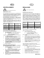
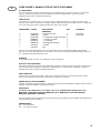
Fig.3
CUTTING CYLINDER TO BOTTOM
BLADE ADJUSTMENT (FIG.3)
To check that the cutting cylinder is set to the bottom
blade correctly, hold a piece of thin paper between
the edge of the blade and the spiral cutters and turn
the cylinder manually.
The paper should be cut cleanly along the total
length of the bottom blade, if not, some adjustment
may be necessary, BUT DO NOT OVERTIGHTEN.
Alternatively if the cylinder is worn it may require
back lapping before adjusting.
To adjust:
1. To adjust the cylinder to the bottom blade lift and
turn alternately left and right hand handwheels (A
Fig.3). (clockwise to put on cut anticlockwise to take
off cut) and release, keep turning the handwheel until
it locates in the serrated locking ring. The adjuster is
of the notched type and each notch is moving the
cylinder in increments of approximately 0.04mm
(0.0015in).
THIS IS A SELF LOCKING MECHANISM THERE
BEING NO NECESSITY TO UNLOCK OR LOCK
THE MECHANISM.
IMPORTANT: IN ROUGH GROUND CONDITIONS
IT MAY BE NECESSARY TO LOCK THE NUTS
SECURING THE BEARING HOUSINGS TO THE
SIDE FRAME WHERE THEY RUN IN ADJUSTING
SLOTS TO RETAIN CYLINDER TO BOTTOM
BLADE SETTINGS. EXPERIENCE WILL DICTATE
THIS. THE NUTS SHOULD NORMALLY BE
TIGHTENED FULLY AND THEN BACKED OFF 1/2
A TURN TO ALLOW HANDWHEEL ADJUSTMENT
WITHOUT THE NEED TO UNLOCK THE NUTS
FIRST.
CUTTING CYLINDER BEARINGS
The cutting cylinder bearings are self adjusting taper
roller bearings and require no adjustments.
FRONT AND REAR ROLL BEARINGS
The roll bearings are self adjusting taper roller
bearings and require no adjustment
Page is loading ...

GB-F-NL-18
GB
END OF SEASON
SERVICING
a. The units should be thoroughly cleaned down to
remove all accumulations of grass clippings and
debris.
b. Turn the cutting cylinders to clean the cutting
edges.
c. Apply a little oil with a brush to the spiral cutters to
prevent rusting.
d. Slowly turn the cylinders which will then spread the
oil on the bottom blades.
WARNING NOTE: Do not turn the cylinders
manually.
Page is loading ...
Page is loading ...

GB-F-NL-21
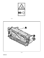
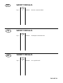
SAFETY DECALS
Location
on Fig.9
Fig.4 A A903494 Caution rotating blades
F
NL
GB
SAFETY DECALS
Location
on Fig.9
Fig.4 A A903494 Voorzichtig! Draaiende messen.
SAFETY DECALS
Location
on Fig.9
Fig.4 A A903494 Attention aux lames rotatives.

GB-F-NL-22
GB
F
NL
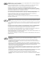
GARANTIE
Toutes nos machines neuves, sauf spécification contraires sur la facture, bénéficient d'une
garantie de 12 mois pièces et main-d'oeuvre.
Toutefois, la garantie ne sera pas acquise si:
L'intervention technique est due à une cause autre que celle d'une utilisation normale du matériel,
Des fournitures autres que celles prévues pour un fonctionnement correct ont été utilisées,
Des modifications ont été apportées au matériel soit par le client lui-même, soit par des
techniciens étrangers à notre organisation.
Le client n'a pas respecté les normes d'installation et d'utilisation.
Dans tous les cas, la garantie cessera automatiquement si le client n'a pas satisfait à ses
obligations contractuelles en matière de paiement.
La garantie exclut, pour notre Société, toute obligation de réparer les dommages directs ou
indirects résultant pour le client de l'utilisation ou du fonctionnement des machines ou relatifs à
cette utilisation ou à leur fonctionnement.
GARANTIE
Wij GARANDEREN dat in het geval van gebrekkig materiaal of vakmanschap, de produkten
binnen TWAALF MAANDEN of tot een maximum van duizend uur na datum van aankoop, ofwel
zullen worden gerepareerd, ofwel dat defecte onderdelen zullen worden vervangen zonder dat
arbeidskosten of materialen, in rekening zullen worden gebracht, mits dat de claim op basis van
deze garantie wordt ingediend via een officiële Jacobsen’ Dealer en mits het defecte onderdeel,
indien dat door ons wordt verzocht, aan de dealer of aan ons zal worden geretourneerd. Deze
garantie vormt een aanvulling op uw wettelijke rechten, wettelijke garanties of andere condities en
hierdoor zal daaraan op geen enkele wijze afbreuk worden gedaan, met uitzondering van het feit
dat wij geen aansprakelijkheid kunnen accepteren voor tweedehands produkten of defecten die
naar onze mening kunnen worden toegeschreven aan misbruik, gebrek aan redelijke verzorging of
onderhoud of normale slijtage, of aan het plaatsen van reserve-onderdelen, nieuwe componenten,
extra componenten die niet door ons voor dat doel zijn geleverd of goedgekeurd. Door het gebruik
van niet door ons aanbevolen oliesoorten of smeermiddelen, zal deze garantie komen te vervallen.
Beschadiging veroorzaakt door transport of beschadiging die het gevolg is van normale slijtage,
valt niet onder deze garantie.
GUARANTEE
We GUARANTEE that should any defect in workmanship or material occur in the goods within
TWELVE MONTHS or to a maximum of one thousand hours from the date of purchase we will
repair, or at our option, replace the defective part without making any charge for labour or for
materials, provided that the claim under this guarantee is made through an authorised Jacobsen'
Dealer and that the defective part shall, if we so request, be returned to us or to the Dealer. This
guarantee is in addition to, and does not exclude, any condition or warranty implied by law, except
that we accept no liability in respect of second-hand goods, or in respect of defects which in our
opinion are in any way or to any extent attributable to misuse, lack of reasonable care or ordinary
wear and tear, or to the fitting of spares, replacements, or extra components which are not
supplied or approved by us for the purpose. The use of non-recommended oil or lubricant nullifies
the guarantee.
Damage through transport or normal wear does not come under the guarantee.

GB-F-NL-23
GB
F
NL
VERKOPEN & SERVICE
Een netwerk van officiële Verkoop- en Service Dealers is opgericht. De adressen kunnen bij uw
leverancier worden aangevraagd.
Als reparaties, onderhoud of reserve-onderdelen - binnen of na de garantieperiode - noodzakelijk
worden geacht voor uw machine dient u, altijd contact op te nemen met uw leverancier of een
officiële dealer. Altijd ook het registratienummer van de machine vermelden.
Wanneer direct na aflevering enige vorm van beschadiging wordt geconstateerd, dient u de
leverancier van de machine daarvan terstond op de hoogte te brengen.
SALES & SERVICE
A network of authorised Sales and Service dealers has been established and these details are
available from your supplier.
When service attention, or spares, are required for the machine, within or after the guarantee
period your supplier or any authorised dealer should be contacted. Always quote the registered
number of the machine.
If any damage is apparent when delivery is made, report the details at once to the supplier of the
machine.
Page is loading ...
Page is loading ...
Page is loading ...
Page is loading ...
Page is loading ...
Page is loading ...
Page is loading ...
Page is loading ...
Page is loading ...
Page is loading ...
Page is loading ...
Page is loading ...
Page is loading ...
Page is loading ...
Page is loading ...
Page is loading ...
Page is loading ...

D-E-I-17
E
3. Ajustar el rodillo delantero a la varilla de ajuste
mediante las dos contratuercas delanteras (J).
4. Hacer lo mismo en el otro extremo de la cuchilla
inferior (cuchilla de asiento).
AJUSTE DEL CILINDRO DE CORTE CON
LA CUCHILLA INFERIOR (ILUST.3)
Para comprobar que el cilindro de corte esté
correctamente ajustado a la cuchilla inferior,
sostenga una pieza de papel fino entre el filo de la
cuchilla y las cuchillas en espiral y gire el cilindro
manualmente.
El papel deberá cortarse limpiamente a lo largo de
toda la extensión de la cuchilla inferior; si no fuera
así, entonces se necesitará efectuar algún ajuste,
PERO NO SE DEBERA APRETAR DEMASIADO.
De manera alternativa, si el cilindro estuviera
gastado, necesitará un esmerilado dorsal previo a
efectuar el ajuste.
Para ajustar:
1. Para ajustar el cilindro a la cuchilla inferior, izar y
girar alternativamente las manillas izquierda y
derecha
(A Ilust.3). (en sentido derecho para poner el corte y
a la izquierda para quitarlo) y liberar. Sígase girando
la manilla hasta que se encaje en la anilla de cierre
dentada. El ajuste es del tipo muescado y cada
muesca mueve el cilindro en incrementos de
aproximadamente 0,04 mm.
ESTE ES UN MECANISMO DE CIERRE
AUTOMATICO, POR LO QUE NO HAY
NECESIDAD DE ABRIR O CERRAR EL
MECANISMO.
IMPORTANTE: EN TERRENOS ACCIDENTADOS,
PUEDE RESULTAR NECESARIO FRENAR LAS
TUERCAS QUE ASEGURAN LOS ALOJAMIENTOS
DE LOS COJINETES AL ARMAZON LATERAL EN
DONDE GIRAN EN LAS RANURAS DE AJUSTE
PARA RETENER EL CILINDRO A LOS AJUSTES
DE LA CUCHILLA INFERIOR. ESTO VENDRA
DICTADO POR LA EXPERIENCIA.
GENERALMENTE LAS TUERCAS SE DEBERAN
APRETAR COMPLETAMENTE Y LUEGO SE
AFLOJARAN 1/2 GIRO PARA PERMITIR EL
AJUSTE DE LA MANILLA SIN NECESIDAD DE
LIBERAR ANTES LAS TUERCAS.
COJINETES DEL CILINDRO DE CORTE
Los cojinetes del cilindro de corte son del tipo de
rodillos cónicos autoajustadores, por lo que no es
necesario efectuar ningún ajuste en los mismos.
COJINETES DE RODILLOS DELANTEROS Y
TRASEROS
Los cojinetes de rodillo son del tipo de rodillos
cónicos autoajustadores, por lo que no es necesario
efectuar ningún ajuste en los mismos.
I
2. Ad una estremità della lama di fondo
(controlama)disporre la barra di regolazione
(G) sul rullo posteriore con la testa della vite
sul labbro della lama di fondo (controlama).
3. Regolare il rullo frontale rispetto alla barra di
regolazione per mezzo dei due controdadi frontali
4. Ripetere per l’altra estremità della lama di
fondo (controlama).
REGOLAZIONE DEL TAMBURO DI TAGLIO
RISPETTO ALLA LAMA DI FONDO (FIG.3)
Per controllare che il tamburo di taglio sia regolato
correttamente rispetto alla lama di fondo, tenere un
pezzetto di carta sottile fra lo spigolo della lama di
fondo e le lame a spirale e girare il tamburo a mano.
La carta deve rimanere tagliata in maniera netta
lungo tutta la lunghezza della lama di fondo,
altrimenti occorre fare delle regolazioni, MA NON
SERRARE TROPPO. Alternativamente, se prima
della regolazione il tamburo è usurato può essere
necessario sottoporlo alla lappatura in senso inverso.
Per regolare:
1. Per regolare la distanza del tamburo rispetto alla
lama di fondo, sollevare e girare alternativamente a
sinistra e a destra le manopole (A Fig.3). (in senso
orario per sottoporre al taglio, in senso antiorario per
togliere dal taglio) e lasciarla andare; continuare a
girare la manopola fino a quando si posiziona
nell’anello di bloccaggio a denti di sega. Il dispositivo
di regolazione è del tipo a tacche e ciascuna tacca
sposta il tamburo in incrementi di circa 0,04 mm.
QUESTO MECCANISMO SI BLOCCA DA SÈ, CIOÈ
NON OCCORRE BLOCCARLO O SBLOCCARLO.
IMPORTANTE: IN CONDIZIONI DI TERRENO
ACCIDENTATO PUÒ RENDERSI NECESSARIO
BLOCCARE I DADI CHE FISSANO LE SEDI DEI
CUSCINETTI ALL’INTELAIATURA DI LATO DOVE
ESSI SCORRONO IN FENDITURE DI
REGOLAZIONE PER MANTENERE LA
REGOLAZIONE DEL TAMBURO RISPETTO ALLA
LAMA DI FONDO. L’ESPERIENZA SUGGERIRÀ DI
AGIRE IN TAL MODO. I DADI DEVONO ESSERE
NORMALMENTE SERRATI APPIENO E POI
ALLENTATI DI 1/2 GIRO PER PERMETTERE LA
REGOLAZIONE PER MEZZO DELLE MANOPOLE
SENZA DOVERE PRIMA SBLOCCARE I DADI.
CUSCINETTI DEI TAMBURI DI TAGLIO
I cuscinetti dei tamburi di taglio sono cuscinetti a rulli
conici del tipo a regolazione automatica e non
richiedono alcuna messa a punto.
CUSCINETTI DEI RULLI ANTERIORI E
POSTERIORI
I cuscinetti dei rulli sono cuscinetti a rulli conici del
tipo a regolazione automatica e non richiedono
alcuna messa a punto.
Page is loading ...
Page is loading ...
Page is loading ...

D-E-I-21
SAFETY DECALS
Location
on Fig.9
Fig.4 A A903494 Achtung! Rotierende Klingen.
E
D
I
ETICHETTE DI SICUREZZA
Ubicazione
su Fig.9
Fig.4 A A903494 Attenzione lame rotanti
SAFETY DECALS
Location
on Fig.9
Fig.4 A A903494 Tenga precaución con las cuchillas si están girando .
Page is loading ...
Page is loading ...
Page is loading ...
Page is loading ...
Page is loading ...
Page is loading ...
Page is loading ...
Page is loading ...
Page is loading ...
Page is loading ...
Page is loading ...
Page is loading ...
Page is loading ...
Page is loading ...
Page is loading ...
Page is loading ...
Page is loading ...
Page is loading ...
Page is loading ...
Page is loading ...
Page is loading ...
Page is loading ...
Page is loading ...

DK-S-SF-21
SAFETY DECALS
Location
on Fig.9
Fig.4 A A903494 Advarsel, roterende blade.
S
DK
SAFETY DECALS
Location
on Fig.9
Fig.4 A A903494 Försiktighet: Roterande blad
SF
SAFETY DECALS
Location
on Fig.9
Fig.4 A A903494 Varo pyöriviä teriä.
Page is loading ...
Page is loading ...
Page is loading ...
Page is loading ...
Page is loading ...
Page is loading ...

28
GB
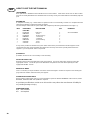
HOW TO USE THE PARTS MANUAL
ITEM NUMBER
Each part which is identified in the illustrations has an item number. Parts which do not have an item number
may not be readily identified in the illustration but are usually closely associated with the immediately adjacent
part.
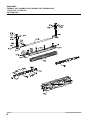
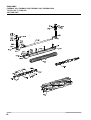
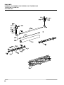
ASSEMBLIES
A complete assembly, e.g. a wheel motor or hydraulic motor or roll assembly, is listed as a complete item with
subsequent individual components listed separately.
The assembly is listed under it's part number with component parts being listed offset to the right, e.g:-
ITEM RANSOMES DESCRIPTION QTY REMARKS
PART NO.
1 LMSD798 Roll Assy. 1 ALL MACHINES
2 MBB4490 • Tube 1
3 LMSD926 • End Cap Assy. 2
4 MBB6851 • • End Cap 1
5 H009116 • • Bearing 1
6 MBB2356 • Seal Housing 1
7 A224016 • Seal 2
* A122192 Screw 2
It may not be possible to illustrate every item. With certain items purchased from outside suppliers some
component parts may not be available from Ransomes and may need to be specially ordered from the
supplier e.g. Volvo hydraulic motor components.
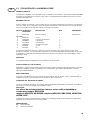
QUANTITIES
Quantities shown are for one assembly or sub-assembly.
USING THE PARTS LIST
Determine the function and application of the part required. Turn to the main index page and select the
appropriate section. Locate the part on the illustration and parts list and read off the quantity from the
appropriate MODEL column.
NUMERICAL INDEX
This is a summary of all part numbers used in the manual arranged in numerical sequence and showing the
page and item number under which the parts appear.
ORDERING OF SPARE PARTS
When ordering replacement parts, it is most important to quote the SERIAL NUMBER of the machine, PART
NUMBER, DESCRIPTION and QUANTITY required.
Any arbitrary modifications carried out on this machine may relieve the manufacturer of liability for
any resulting damage or injury.
ABBREVIATIONS
N/A Not Available
AR As Required
Page is loading ...
Page is loading ...
Page is loading ...
Page is loading ...
Page is loading ...
Page is loading ...
Page is loading ...
Page is loading ...

37
GB
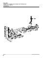
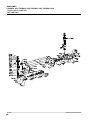
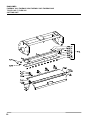
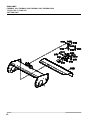
INDEX TO SECTIONS
SECTION PAGE
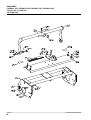
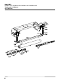
Common Parts - Bottom Block and Concave ......................................................................................................... 51
Common Parts - Concave (fairway 250, T-Plex 185 series UL) ............................................................................. 53
Common Parts - Cylinder Bearing Housings .......................................................................................................... 47
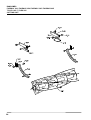
Common Parts - Main Frame and Mounting ...........................................................................................................39
Common Parts - Rear Roll (Fairway 250) ............................................................................................................... 41
Common Parts - Rear Roll (Fairway 300, 305, 405, T-Plex 185 series UL) ........................................................... 43
Common Parts - Rear Roll (T-Plex 185 series US, T -Plex 285) ............................................................................ 45
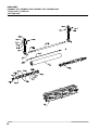
Cutting Cylinder and Front Grooved Roll (Floating Head)(Fairway 300, 305, 405, T-Plex 185 series RE, ST) ...... 55
Cutting Cylinder and Front Grooved Roll (Floating Head) (Fairway 250) ...............................................................59
Cutting Cylinder and Front Grooved Roll (Floating Head) (T-Plex 185 series US, T-Plex 285).............................. 61
Cutting Cylinder and Front Plain Roll (Floating Head)(Fairway 250, 300, 305, 405,
T-Plex 185 series RE, ST, UL)................................................................................................................................ 67
Cutting Cylinder and Front Plain Roll (Floating Head) (T-Plex 185 series US, T-Plex 285)....................................69
Cutting Cylinder and Skids (Fixed Head) (T-Plex 185 / 285) .................................................................................. 65
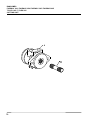
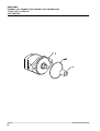
Drive Assembly (Danfoss)(Fairway 300) ................................................................................................................ 71
Drive Assembly (Ultra)(T-Plex 185, 285, Fairway 305, 405)................................................................................... 73
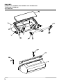
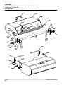
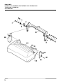
Grassbox and Fixings (T-Plex 185 series UL) ........................................................................................................ 75
Grassbox and Fixings (T-Plex 185 series ST, RE) ................................................................................................. 77
Grassbox and Fixings (Fairway 305 / 405) ............................................................................................................. 79
Page is loading ...
Page is loading ...
Page is loading ...
Page is loading ...
Page is loading ...
Page is loading ...
Page is loading ...
Page is loading ...
Page is loading ...
Page is loading ...
Page is loading ...
Page is loading ...
Page is loading ...
Page is loading ...
Page is loading ...
Page is loading ...
Page is loading ...
Page is loading ...
Page is loading ...
Page is loading ...
Page is loading ...
Page is loading ...
Page is loading ...
Page is loading ...
Page is loading ...
Page is loading ...
Page is loading ...
Page is loading ...
Page is loading ...
Page is loading ...
Page is loading ...
Page is loading ...
Page is loading ...
Page is loading ...
Page is loading ...
Page is loading ...
Page is loading ...
Page is loading ...
Page is loading ...
Page is loading ...
Page is loading ...
Page is loading ...
Page is loading ...
Page is loading ...
Page is loading ...
-
 1
1
-
 2
2
-
 3
3
-
 4
4
-
 5
5
-
 6
6
-
 7
7
-
 8
8
-
 9
9
-
 10
10
-
 11
11
-
 12
12
-
 13
13
-
 14
14
-
 15
15
-
 16
16
-
 17
17
-
 18
18
-
 19
19
-
 20
20
-
 21
21
-
 22
22
-
 23
23
-
 24
24
-
 25
25
-
 26
26
-
 27
27
-
 28
28
-
 29
29
-
 30
30
-
 31
31
-
 32
32
-
 33
33
-
 34
34
-
 35
35
-
 36
36
-
 37
37
-
 38
38
-
 39
39
-
 40
40
-
 41
41
-
 42
42
-
 43
43
-
 44
44
-
 45
45
-
 46
46
-
 47
47
-
 48
48
-
 49
49
-
 50
50
-
 51
51
-
 52
52
-
 53
53
-
 54
54
-
 55
55
-
 56
56
-
 57
57
-
 58
58
-
 59
59
-
 60
60
-
 61
61
-
 62
62
-
 63
63
-
 64
64
-
 65
65
-
 66
66
-
 67
67
-
 68
68
-
 69
69
-
 70
70
-
 71
71
-
 72
72
-
 73
73
-
 74
74
-
 75
75
-
 76
76
-
 77
77
-
 78
78
-
 79
79
-
 80
80
-
 81
81
-
 82
82
-
 83
83
-
 84
84
-
 85
85
-
 86
86
-
 87
87
-
 88
88
-
 89
89
-
 90
90
-
 91
91
-
 92
92
-
 93
93
-
 94
94
-
 95
95
-
 96
96
-
 97
97
-
 98
98
-
 99
99
-
 100
100
-
 101
101
-
 102
102
-
 103
103
-
 104
104
-
 105
105
-
 106
106
-
 107
107
-
 108
108
-
 109
109
-
 110
110
-
 111
111
-
 112
112
-
 113
113
-
 114
114
-
 115
115
-
 116
116
-
 117
117
-
 118
118
-
 119
119
-
 120
120
-
 121
121
-
 122
122
-
 123
123
-
 124
124
-
 125
125
-
 126
126
-
 127
127
-
 128
128
-
 129
129
-
 130
130
-
 131
131
-
 132
132


Ask a question and I''ll find the answer in the document
Finding information in a document is now easier with AI
in other languages
- italiano: Ransomes T-Plex 185
- français: Ransomes T-Plex 185
- español: Ransomes T-Plex 185
- Deutsch: Ransomes T-Plex 185
- Nederlands: Ransomes T-Plex 185
- dansk: Ransomes T-Plex 185
- svenska: Ransomes T-Plex 185
- suomi: Ransomes T-Plex 185
Related papers
-
Ransomes LMAC071 Accessories Manual
-
-
-
-
-
-
-
-
-