
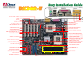
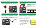
MIC-In
Line-In
Speaker Out
ATX Power Connector
2200
μ
F Low ESR Capacitors
Resettable Fuse
AGP 4x Expansion Slot
370-pin CPU Socket with Voltage &
Frequency Auto-detection
supports Intel
®
Pentium™ III (Both
Coppermine & Tualatin with 512K Cache
are supported) & one Celeron
533MHz~1.2GHz+ CPU
VIA Apollo Pro 133T Chipset with
Enlarged Aluminum Heatsink
CPU Fan (with H/W Monitoring)
PC133 DIMM Slot x4
FDD Connector
ATA33/66/100 IDE Connector x2
JP23 FSB Select Jumper
AC’97 CODEC Chipse
t
Front Audio Connecto
r
AUX-IN
MODEM-CN
CD-IN
JP12 On-board Sound
Enable/Disable Jumpe
r
CNR Expansion Slot
32bit PCI Expansion Slot x 5
IrDA Connecto
r
Support 2
n
d
USB Por
t
WOL (Wake On LAN)
Dr. LED Connecto
r
Front Panel Connecto
r
FAN3 (with H/W Monitoring)
JP14 Clear CMOS Jumper
PS/2 Mouse
Connector
PS/2 Keyboard
Connector
USB Port
COM 1 Port
Game Port
SPP/EPP/ECP
Parallel Port
IDE RAID Connector x2
JP28 Keyboard/Mouse
Wake up Jumper
FAN2 (with H/W Monitoring)
RJ45 LAN
Connector
LSI 80225 Chipse
t
Chassis Intrusion Connecto
r

1. JP14 Clear CMOS
2. JP12 Enable/Disable Onboard Audio
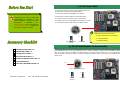
Everything you need to boot this
motherboard is included in this
Easy Installation Guide. For more
information, a complete Online
User's Manual can be found in the
Bonus Pack CD Disc. Thanks fo
r
the help of saving our earth!
PART NO: 49.89I10.E01 DOC. NO: DX34RU-EG-E0112B
Hard Drive IDE Cable x 1
80-Wire IDE Cable x 1
Floppy Drive Cable x 1
Bonus Pack CD disc x 1
FastTrack 100 Lite driver disc x 1
Online Manual x 1
This Easy Installation Guide x 1
Tip: When should I Clear CMOS?
1. Boot fail because of overclocking…
2. Forget password…
3. Troubleshooting…
You can clear CMOS to restore system default setting. To
clear the CMOS, follow the procedure below.
1. Turn off the system and unplug the AC power.
2. Remove ATX power cable from connector PWR2.
3. Locate JP14 and short pins 2-3 for a few seconds.
4. Return JP14 to its normal setting by shorting pin 1 & pin 2.
5. Connect ATX power cable back to connector PWR2.
JP12 Onboard Audio jumpe
r
Pin 1
This motherboard has AC’97 sound onboard. JP12 is used to enable or disable onboard AD1885 CODEC
chip. If you don’t want to enable the Onboard Audio, you should set this jumper to 2-3, and disable the
“OnChip Sound” from BIOS setting > Advanced Chipset Features, before you install your preferred PCI
Sound Card.
Enable
(Default)
Disable
11
Normal Operation
(default)
Clear CMOS
11

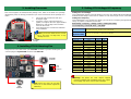
Plug in the CPU fan cable to the 3-pin CPU FAN connector. If you have housing fan, you
can also plug it on System FAN connector and AUX FAN.
CPU CPU Core Frequency FSB Clock Ratio
Celeron 533 533MHz 66MHz 8x
Celeron 566 566MHz 66MHz 8.5x
Celeron 600 600MHz 66MHz 9x
Pentium III 600E 600MHz 100MHz 6x
Pentium III 650E 650MHz 100MHz 6.5x
Pentium III 700E 700MHz 100MHz 7x
Pentium III 750E 750MHz 100MHz 7.5
Pentium III 800E 800MHz 100MHz 8x
Pentium III 850E 850MHz 100MHz 8.5x
Pentium III 533EB 533MHz 133MHz 4x
Pentium III 600EB 600MHz 133MHz 4.5x
Pentium III 667EB 667MHz 133MHz 5x
Pentium III 733EB 733MHz 133MHz 5.5
Pentium III 800EB 800MHz 133MHz 6x
Pentium III 866EB 866MHz 133MHz 6.5
Pentium III 933EB 933MHz 133MHz 7x
Pentium III 1G 1GHz 133MHz 7.5x
Pentium III 1.13G 1.13GHz 133MHz 8.5x
Setting CPU Core Voltage
This motherboard supports CPU VID function. The CPU core voltage will be automatically
detected and the range is from 1.05V to 1.825V. It is not necessary to set CPU Core Voltage
Setting CPU Frequency
This motherboard is CPU jumper-less design, you can set CPU frequency through the BIOS
setup, no jumpers or switches are needed.
BIOS Setup > Frequency / Voltage Control > CPU Speed Setup
Core Frequency = CPU FSB Clock * CPU Ratio
CPU Ratio
3x, 3.5x, 4x, 4.5x, 5x, 5.5x, 6x, 6.5x, 7x, 7.5x, 8x, 8.5x, 9x, 9.5x, 10x, 10.5x, 11x, 11.5x,
12x, 12.5x, 13x, 13.5x, 14x, 14.5x, 15x, 15.5x and 16x
CPU FSB
(By BIOS Table)
66.6, 79, 83.3, 85, 87.5, 90, 92.5, 95, 100, 110, 120, 124, 129, 133.3, 138, 143, 147, 152,
154, 157, 159, 162, 166, 171, 180, 190, and 200 MHz
5. Setting CPU Voltage & Frequency
4. Installing CPU & Housing Fan
3. Installing Processor
Warning: VIA Apollo Pro 133T chipset supports
maximum 133MHz FSB and 66MHz AGP clock, highe
r
clock setting may cause serious system damage.
1. Pull up the CPU socket lever and up to
90-degree angle.
2. Locate Pin 1 in the socket and look for a
(golden) cut edge on the CPU upper interface.
Match Pin 1 and cut edge. Then insert the
CPU into the socket.
3. Press down the CPU socket lever and finish
CPU installation.
Note: If you do not match the CPU socke
t
Pin 1 and CPU cut edge well, it ma
y
damage the CPU.
CPU Pin1 and
cut edge
CPU socket
Lever
Note: Some CPU fans do not have
sensor pin, so that cannot support fan
monitoring.
CPU FAN2
Connector
FAN3
Connector
GND
+12V
SENSOR
CPU FAN
Connector
This socket supports FC-PGA/FCPGA2 package CPU, which is the latest CPU package
developed by Intel, we strongly recommend you not to insert former PPGA-package CPU
onto it.

Secondary
Slave (4th)
Primary
Master
(
1st
)
Primary
Slave
(
2nd
)
Secondary
Master (3rd)
Pin 1
Pin 1
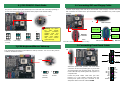
7.JP28 Keyboard/Mouse Wake-up
6. JP23 FSB/PCI Clock Ratio
8. Connecting IDE and Floppy Cable
9. Connecting Front Panel Cable
The JP23 is used to specify the relationship of PCI and FSB clock. Generally speaking, if
you are not overclockers, we recommend set the jumper at the default setting.
Connect 34-pin floppy cable and 40-pin, 80-wire IDE cable to floppy connector FDC and
IDE connector. Be careful of the pin1 orientation. Wrong orientation may cause system
damage.
Pin 1
IDE2 (Secondary)
Pin 1
IDE1 (Primary)
FDD Connector
IDE Connector
1
Speaker
IDE LED
+
+
+
SPWR
+
ACPI &
Power LED
Reset
1
SPWR
GND
ACPILED-
GND
ACPILED
NC
NC
GND
RESET
GND
NC
NC
+5V
IDE LED
IDE LED
+5V
+5V
GND
NC
SPEAKER
A
ttach the power LED, speaker, and reset switch
connectors to the corresponding pins. If you enable
“Suspend Mode” item in BIOS Setup, the ACPI &
Power LED will keep flashing while the system is in
suspend mode.
Locate the power switch cable from your ATX
housing. It is 2-pin female connector from the
housing front panel. Plug this connector to the
soft-power switch connector marked SPWR.
1
FSB=133MHz
1
FSB=100MHz
1
FSB=66MHz
1
Auto Detect
(Default)
Warning: VIA Apollo
Pro 133T chipset
supports maximum
133MHz FSB and
66MHz AGP clock,
higher clock setting
may cause serious
s
y
stem dama
g
e.
This motherboard provides Keyboard/Mouse wake-up function. You can use the JP28 to
enable or disable this function.
Pin 1
Disable
(Default)
Enable
1
1
IDE RAID
Connector
IDE RAID 2 (Secondary)
IDE RAID 1 (Primary)
Pin 1

Connector Pin1 Pin2 Pin3 Pin4
CD-IN
Left GND GND Right
MODEM-CN
Mono In GND GND Mic Out
AUX-IN
Left GND GND Right
Pin 1
12. Connecting CD / MODEM / AUX
10. Front Audio
11. Support 10/100 Mbps LAN onboard
If the housing has been designed with an audio port on the front panel, you’ll be able to
connect onboard audio to front panel through this connector. By the way, please remove
the jumper cap from the Front Audio Connector before you connect the cable. Do no
t
remove this yellow jumper cap if housing without an audio port on the front panel.
The CD-IN connector is used to connect CD Audio
cable from CDROM or DVD drive to onboard sound.
The MODEM-CN connector is used to connect
Mono In/ Mic Out cable from internal modem card to
onboard sound circuit.
The AUX-IN connector is used to connect MPEG
Audio cable from MPEG card to onboard sound.
AUX-IN
MODEM-CN
CD-IN
VIA Apollo Pro 133T chipset includes a fast Ethernet controller on chip. On the strength of
LSI 80225 PHY on board, which is a highly-integrated Platform LAN Connect device, it
provides 10/100M bps Ethernet for office and home use, the Ethernet RJ45 connector is
located on top of USB connectors. The green LED indicates the link mode, it lights when
linking to network and blinking when transferring data. The orange LED indicates the
transfer mode, it will light when transferring data in 100Mbps mode.
Green/ACT
Yellow/Speed
FP_MIC
NC
PHONE_R
NC
PHONE_L
GND
+5V
JS1
KEY
NC
1 2
9 10
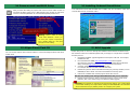
13. Installing LAN Driver (Optional)
The South Bridge in VIA Apollo 133T chipset integrates a total communication solution including
10/100Mb Fast Ethernet for Office requirement. You can install LAN Driver under Windows
95/98/ME, WindowsNT4 & Windows2000 by following steps.
Manually Adding an Adapter in Windows 95 / 98 / ME / NT4 / 2000:
=====================================
LOCATION OF DRIVER: \Driver\LAN\RTL8100\Windows\
(Depend on various Windows version in your system.)
1. From the Control Panel, double-click the “Add Hardware” icon.
2. Double-click Other Devices or Network Adapters in the list area.
3. Double-click a PCI Ethernet Controller.
4. Click the Driver tab, then click Update Driver.
5. Click Next at the Update Device Driver Wizard.
6. Select "Display a list of all the drivers..." and click Next.
7. Insert the AOpen Bonus CD and click Have Disk.
8. Enter the appropriate drive for your disc media
(for example: D:\) ,and click OK.
9. Click OK at the Select Device dialog box.
10. The Update Wizard displays the message that it has found
the driver. Click Next.
11. Click Finish and restart your computer when prompted.
Note: If the New Hardware
Found dialog box does no
t
appear at startup and yo
u
cannot connect to the network,
check the Device Manager lis
t
to see if the new adapter i
s
p
resent. If it is not, please instal
l
the LAN driver manually.

After you finish the setting of jumpers and connect correct cables. Power on
and enter the BIOS Setup, press <Del> during POST (Power On Self Test).
Choose "Load Setup Defaults" for recommended optimal performance.
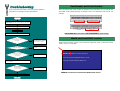
14. Power-on and Load BIOS Setup
15. AOpen Bonus Pack CD
17. BIOS Upgrade
AOpen Easy Flash is more user friendly than traditional flash method. The BIOS binary
file and flash routine are combined together and you simply run a single file to complete
the flash process.
1. Download new BIOS upgrade zipped file from AOpen's web site. For example,
DX34RU102.ZIP.
2. Run shareware PKUNZIP (http://www.pkware.com/
) which supports
miscellaneous operation systems to extract the binary BIOS file and the flash
utility. Or Winzip (http://www.winzip.com/
) in Windows environment.
3. Save the unzipped file into a bootable floppy disk.
For example, DX34RU102.BIN & DX34RU102.EXE
4. Reboot the system to DOS mode without loading any memory handler (such as
EMM386) or device driver. It needs around 520K free memory space.
5. Execute A:> DX34RU102 and the program will do the rest of it.
DO NOT turn off the power during FLASH PROCESS until you are asked to!!
6. Reboot system and press <Del> to enter BIOS Setup, Choose "Load Setup
Defaults", then “Save & Exit Setup” and finish the BIOS upgrade.
Warning: The upgrade of new BIOS will permanently replace your original BIO
S
content after flashing. The original BIOS setting and Win95/Win98 PnP information
will be refreshed and
y
ou
p
robabl
y
need to re
-
confi
g
ure
y
our s
y
stem.
16. Installing Onboard Sound Driver
You can use the autorun menu of Bonus CD disc. Choose the utility and driver and select
model name.
Del
Warning: Please avoid of usin
g
"Load Turbo Defaults", unless yo
u
are sure your system component
s
(CPU, DRAM, HDD, etc.) are goo
d
enou
g
h for turbo settin
g
.
This motherboard comes with AD 1885 AC97 CODEC chip, you can find the audio driver
from the Bonus Pack CD autorun menu.

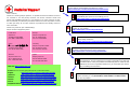
If you encounter any trouble to boot you system, follow the
procedures accordingly to resolve the problem.
Part Number and Serial Number
The Part Number and Serial number are printed on bar code label. You can find this ba
r
code label on the outside packing, on ISA/CPU slot or on component side of PCB. Fo
r
example:
Model name and BIOS version
DX34R-U R1.00 Feb. 04. 2001 AOpen Inc.
Award Plug and Play BIOS Extension v1.0A
Copyright © 1998, Award Software, Inc.
Model name and BIOS version can be found on upper left corner of first boot screen
(POST screen). For example:
DX34R-U is model name of motherboard, R1.00 is BIOS version.
Make sure if the jumper settings for CPU and DRAMs are correct.
Clear CMOS.
Install the VGA card. Then connect your monitor and keyboard.
The problem was probably caused
by power supply or motherboard
failure. Please contact your reselle
r
or local distributor for repairing.
Perhaps your VGA card or monito
r
is defective.
No
Yes
No
Yes
It is very possible that your keyboard
is defective.
During system rebooting, press Del to enter BIOS Setup. Choose
“Load Setup Default".
The problem should be caused by the
IDE cables or HDD itself.
Re-install Windows 95, Windows 98 or Windows NT.
Yes
Yes
Turn off the power and unplug the AC power cable, then remove all
of the addon cards and cables, including VGA, IDE, FDD, COM1,
COM2 and Printer.
Turn on the power, and check if
the power supply and CPU fan
work properly.
Start
Check if there is display.
Press Ctrl, and Alt key at the
same time, hold them and then
press Del to see if the
s
y
stem reboots.
Turn off the system and
re-connect the IDE cable.
Check if the system can
reboot successfully.
End
No
No
P/N: 91.88110.201 is part number, S/N: 91949378KN73 is serial number.
Part No. Serial No.
Part No.
Serial No.

Dear Customer,
Thanks for choosing AOpen products. To provide the best and fastest service to
our customer is our first priority. However, we receive numerous emails and
p
hone-calls worldwide everyday, it is very hard for us to serve everyone on time.
We recommend you follow the procedures below and seek help before contact
us. With your help, we can then continue to provide the best quality service to
more customers.
Thanks very much for your understanding!
A
Open Technical Supporting Team
Online Manual: Please check the manual carefully and make sure the
jumper settings and installation procedure are correct.
http://www.aopen.com/tech/download/manual/default.htm
1
1
Test Report: We recommend to choose board/card/device from the
compatibility test reports for assembling your PC.
http://www.aopen.com/tech/report/default.htm
2
2
FAQ: The latest FAQ (Frequently Asked Questions) may contain a
solution to your problem.
http://www.aopen.com/tech/faq/default.htm
5
5
Download Software: Check out this table to get the latest updated
BIOS/utility and drivers.
http://www.aopen.com/tech/download/default.htm
3
3
News Group: Your problem probably had been answered by our support
engineer or professional users on the news group.
http://www.aopen.com/tech/newsgrp/default.htm
4
4
Contact Distributors/Resellers: We sell our products through resellers
and integrators. They should know your system configuration very well and
should be able to solve your problem more efficiently than us. After all, their
attitude of service is an important reference for you if next time you want to
buy something else from them.
6
6
Contact Us: Please prepare detail system configuration and error symptom
before contacting us. The part number, serial number and BIOS version
are also very helpful.
7
7
Pacific Rim
AOpen Inc.
Tel: 886-2-3789-5888
Fax: 886-2-3789-5899
America
AOpen America Inc.
Tel: 1-408-922-2100
Fax: 1-408-922-2935
Europe
AOpen Computer b.v.
Tel: 31-73-645-9516
Fax: 31-73-645-9604
Germany
AOpen Computer GmbH.
Tel: 49-2102-157700
Fax: 49-2102-157799
China
艾尔鹏国际上海(股)有限公司
Tel: 86-21-6225-8622
Fax: 86-21-6225-7926
Web Site: http://www.aopen.com
E-mail: Send us email by going through the contact form below.
English http://www.aopen.com/tech/contact/techusa.htm
Japanese http://www.aopen.co.jp/tech/contact/techjp.htm
Chinese http://www.aopen.com.tw/tech/contact/techtw.htm
German http://www.aopencom.de/tech/contact/techde.htm
French http:/france.aopen.com/tech/contact/techfr.htm
Simplified Chinese http://www.aopen.com.cn/tech/contact/techcn.htm
Japan
AOpen Japan Inc.
Tel: 81-048-290-1800
Fax: 81-048-290-1820
-
 1
1
-
 2
2
-
 3
3
-
 4
4
-
 5
5
-
 6
6
-
 7
7
-
 8
8


Ask a question and I''ll find the answer in the document
Finding information in a document is now easier with AI
Related papers
-
AOpen MX34-U Easy Installation Manual
-
-
-
-
-
-
-
-
-