Page is loading ...


LPDT User’s Manual
i
When calling your representative for technical support,
please have your serial numbers available.
The Sensor and Instrument Serial Numbers are on the
instrument, also see section 3.4.4.4.
Sensor Serial No.: _______________
Instrument Serial No.: _______________
Your Representative is:
Check the Internet for updates; the latest revision of this
manual is available in Adobe Acrobat format at:
http://www.xentaur.com
COSA INSTRUMENT CORPORATION
55 Oak Street, Norwood, NJ 07648
Tel: 1(201) 767-6600 - Fax: 1(201) 767-6804
e-mail: cosa@cosaic.com
Except as may be provided by contract, this document and all
specifications and drawings contained are the property of Xen-
taur Corporation, are issued in strict confidence, and shall not
be reproduced or copied or transmitted, in any form or by any
means, or used as the basis for the manufacture or sale of appa-
ratus, programs, or services without permission.
Document No.: LDO.01.D.2000 Rev.0 6/1/99
Copyright © 1999 by Xentaur Corporation

LPDT User’s Manual
ii
Xentaur reserves the right to change or modify the product
specification and / or appearance at any time without notice.
Therefore, the information in this document is subject to
change without notice and does not represent a commitment
on the part of Xentaur Corporation.
Swagelok, Cajon are trademarks of SWAGELOK Co.
Acrobat is a trademark of Adobe Systems Incorporated
Microsoft Windows is a registered trademark of Microsoft Corporation
HTF is a trademark of Xentaur Corporation
SpanCheck is a trademark of Xentaur Corporation
The Xentaur Logo is a trademark of Xentaur Corporation
The customer agrees that in accepting and using this instru-
ment Xentuar Corporation’s liability arising from or in any
way connected with this instrument shall be limited exclu-
sively to performing a new calibration or replacement or
repair of the instrument or sensor, at Xentaur’s sole option,
as covered by Xentaur’s warranty. In no event shall Xentaur
be liable for any incidental, consequential or special dam-
ages of any kind or nature whatsoever, including but not
limited to lost profits arising from or in any way connected
with this instrument or items hereunder, whether alleged to
arise from breach of contract, express or implied warranty,
or in tort, including without limitation, negligence, failure to
warn or strict liability.

LPDT User’s Manual
iii
Examine the LPDT package for damage or mishan-
dling. If any damage is evident notify the carrier
and request an inspection.
Unpack the box, it should contain: The LPDT with
sensor in desiccant container, connectorized cable,
and this manual.
PLEASE READ THIS MANUAL IN WHOLE,
PRIOR TO INSTALLING OR REMOVING THE
SENSOR FROM ITS SHIPPING CONTAINER.
This manual is organized in three sections:
Section 1 is an overview of the LPDT.
Section 2 describes the sensor and sampling tech-
niques.
Section 3 describes the instrument’s electrical,
mechanical, and user interfaces.
This manual is intended for those already familiar
with the installation, use and maintenance of ana-
lytical or process instrumentation.
Those acquainted with other Xentaur dewpoint
measurement products such as the XDT or the
XPDM, will benefit from the commonality of the
user interface.

LPDT User’s Manual
iv
Warranty
Xentaur instruments are warranted to be free from defects in
workmanship and materials. Liability under this warranty is lim-
ited to servicing, calibrating, and replacing any defective parts of
the instrument returned to the factory for that purpose. Fuses are
specifically excluded from any liability. This warranty is effective
from the date of delivery to the original purchaser. The equipment
must be determined by Xentaur to have been defective for the
warranty to be valid. This warranty applies as follows:
• one year for electronics
• one year for mechanical failures to the sensor
• six months for calibrations
If damage is determined to have been caused by misuse or abnor-
mal conditions of operation, the owner will be notified and
repairs will be billed at standard rates after approval.
Maintenance Policy
In cases when equipment fault is suspected, please notify your
representative of the problem, be sure to provide them with model
and serial numbers. If the problem can not be resolved, then ask
for a Return Authorization Number (RAN) and shipping instruc-
tions. Issuance of an RAN does not automatically imply that the
equipment is covered by our warranty, that will be determined
after we receive the equipment. Pack the equipment in a suitable
box with sufficient padding, include the RAN number on your
paperwork, and send the equipment, prepaid, to the designated
address. Xentaur will not accept equipment returned without an
RAN, or with reversed shipping or import/export charges.
If the warranty has expired, or the damage is due to improper use
or exposure of the equipment; then Xentaur will provide an esti-
mate and wait for approval before commencing repairs.
For your convenience a Return Authorization Request Form is
provided in appendix J, it must be filled out and sent back to Xen-
taur in order to obtain a RAN.

LPDT User’s Manual
v
LPDT User’s Manual Table of Contents
1.0 Overview of the LPDT ...........................................1
2.1 Precautions using the sensor ...................................3
2.2 Sensor Technical Specifications .............................4
2.3 Sensor Installation & Sampling Techniques ...........4
2.3.1 In-situ Installation ................................................5
2.3.2 Extractive Installation ..........................................7
2.4 Troubleshooting unexpected readings ....................9
3.1 Precautions using the LPDT .................................13
3.1.1 Electromagnetic Compatibility Considerations .13
3.2 Instrument Technical Specifications .....................14
3.3 Installation ............................................................15
3.3.1 Mechanical Installation ......................................15
3.3.2 Electrical Installation .........................................16
3.4 Operating the Instrument ......................................17
3.4.1 Starting up ..........................................................17
3.4.2 Display Conventions ..........................................17
3.4.3 Push Buttons ......................................................19
3.4.4 Operating State ..................................................19
3.4.4.1 Viewing Dewpoint Mode ................................20
3.4.4.2 Viewing Temperature at the Sensor ................20
3.4.4.3 Start Calibration (SpanCheck™) Mode ..........21
3.4.4.4 Viewing Serial Number Mode ........................24
3.4.5 SetUp State ........................................................24
3.5 Troubleshooting the Instrument ............................28
Appendix A: Operating State User Interface flowchart 31
Appendix B: Set-Up State User Interface flowchart ...32
Appendix C: LPDT Mechanical Drawing ..................34
Appendix D: LPDT Electrical Connections ...............35
Appendix E: Sensor/SpanCheck™ Theory of Operation 36
Appendix F: Pressure Correction ................................39
Appendix G: Current vs. Dewpoint ............................40


Section 1: Introduction
page 1
1.0 Overview of the LPDT
The LPDT is a microprocessor based 4-20mA loop powered
(2 wire) hygrometer, for measuring moisture content in
gases in the range from -100°C to +20°C. The measurement
is displayed on the instrument’s custom LCD, and is trans-
mitted by varying the current drawn (4-20mA) from the
power supply. The current varies linearly proportional to the
selected measurement units. An optional digital output is
available which modulates/demodulates the 4-20mA loop
line without interfering with its operation. With this option
the LPDT is capable of communicating with properly
equipped Personal Computers or other RS-232 capable con-
trollers. Three front panel buttons provide the user with a
wide variety of features. The LPDT’s advanced design
allows it to be housed in a small stainless steel enclosure
behind the sensor probe, thus the instrument and sensor are
a single integrated unit.
The LPDT uses the Xentaur HTF™ sensor which is encap-
sulated in sintered stainless steel, thus it is capable of com-
ing into contact with a wide variety of environments.
However one should keep in mind that the sensor is a sensi-
tive device and it should be handled accordingly.

LPDT User’s Manual
page 2

Section 2: Sensor and Sampling Techniques
page 3
2.1 Precautions using the sensor
The Xentaur HTF™ Al2O3 sensor is designed and field
proven to be highly reliable, rugged and maintenance free.
However the user should consider the following precau-
tions:
• To avoid the need for prolonged dry-down (when
expecting to measure dewpoints dryer than -65ºC), do
not expose the sensor to room air longer than necessary
(1 - 2 minutes). Thus, do not open the sensor container
before you are ready to install the sensor.
• The sensor container has desiccant to keep the sensor
dry during shipping and to avoid damage due to conden-
sation. Close the container immediately after removing
the sensor to avoid degradation of the desiccant.
• Do not throw away the sensor container, you may use it
again to transport the sensor between locations, to store
it between uses or to ship it back to the factory for certi-
fication. The container can be attached to the loop cable,
by trapping the cable with the lid strap.
• Do not expose the sensor to corrosive gases such as
gases containing chlorine, ammonia or HCl. (SO2 can
be monitored when the moisture content is low).
• Except for the XTR65W sensor:
1. Do not expose the sensor to liquid water, as it may get
damaged.
2. Do not breathe directly onto the sensor, as condensa-
tion may form which could damage the sensor element.
• Do not install the sensor near heat sources such as radia-
tors or air ducts.
• Do not install the sensor in places subject to extreme
mechanical vibration or shock. If this is not avoidable,
use resilient mounting. If in doubt, call your representa-

LPDT User’s Manual
page 4
tive.
• Do not disassemble the porous metal filter encapsula-
tion, as this will damage the sensor and void your fac-
tory warranty.
• Prior to installation of the probe, ensure that no contam-
inants are present in the system (e.g. oil, liquid water).
2.2 Sensor Technical Specifications
Type: .................................Hyper Thin Film high capacitance Al2O3.
Dewpoint range:
XTR-100........................-148°F to +68°F (-100°C to +20°C)
XTR-65..........................-85°F to +68°F (-65°C to +20°C).
Capacitance:......................15nF to 200nF.
Accuracy:..........................±5.5°F (±3°C).
Repeatability:....................±0.9°F (±0.5°C).
Response time:..................see graph in Appendix I.
Temperature range:...........-10°C to +70°C.
Sample Flow range:
(linear velocity @ 1ATM):Static to 100m/s.
Storage temperature:.........-40°F to+176°F (-40°C to +80°C).
Mechanical:.......................encapsulated in 100µ sintered stainless steel.
Calibration method: ..........SpanCheck™, sensor saturates at dewpoint above
+68°F (+20°C). NIST/NPL traceable multi-point
factory calibration available optionally.
2.3 Sensor Installation & Sampling Techniques
Keep in mind that the moisture content at the sensor is not
only due to the moisture of the gas being measured, but also
due to desorption of water from tubing, trapped moisture (at
the interconnection points, valves, filters and other hygro-
scopic materials in the system), leaks in the system, and oth-
ers. Thus the measurement may vary from the expectation,
and therefore care should be taken in choosing the sampling
technique utilized in the measurement. Factors such as gas
pressure, flow rate, materials of construction, length and

Section 2: Sensor and Sampling Techniques
page 5
diameter of tubing, number of interconnecting fittings, dead
space in tubing and manifolds; will influence the measure-
ment value and response time.
The high capacitance HTF™ sensors can be installed either
directly in the line to be sampled (in-situ), or in a slip stream
of a sample system (extractive).
To assure a long and accurate performance of the sensor, it
should be protected from contaminants such as liquids
(water, oil etc.), and particulates. The sintered stainless steel
sensor encapsulation protects from particulates larger than
100 microns, finer particulates (e.g. from degraded desic-
cant or rust) should be filtered with a particulate filter with
suitable capability, do not use hygroscopic filter materials.
2.3.1 In-situ Installation
In-situ installation is recommended only for measurements
where the gas pressure is expected to vary little, the gas is
expected to be free of contaminants, the gas temperature is
within the operating specifications of the sensor, and there is
no chance of liquids coalescing. Examples of applications
suited for in-situ installations are: pure gases, output of des-
iccant dryers (for instrument air), glove boxes, etc. For most
other applications in-situ installation should be avoided for
the following reasons:
• Sample conditioning is almost always necessary to
avoid exposure of the sensor to liquid water and other
contaminants, such as hydrocarbons, which may dam-
age the sensor over time.
• Variations in line pressure affect the reading of the sen-
sor because dewpoint varies with pressure.
• If the gas line is under pressure, it is more likely that
water condensation occurs which may damage the sen-
sor.

LPDT User’s Manual
page 6
• Under a pressurized system removal of the sensor with-
out the installation of isolation valves can be dangerous.
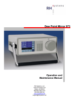
If in-situ installation is required, bypass mounting is prefer-
able; make sure to install the sensor at the upper surface of
the gas line to minimize its exposure to liquid water, should
condensation occur, the XTR65W sensor is best suited for
these applications. Also consider the need to isolate (depres-
surize) before installing or removing the sensor.
Main
Gas Line
LPDT
LPDT
4-20mA loop cable
Safety shut-off Valve
Bypass
Control
Valve *
Safety shut-off Valve
Bypass Installation, Sensor
Measuring at Line Pressure
In-Line Installation, Sensor
Measuring at Line Pressure
Main
Gas Line
4-20mA loop cable
oint Transmitter
Ma
Se
Mo
Think
Safety
Read
Manual
www.xentaur.com NOT RECOMMENDED
Sample Cell
oint Transmitter
Ma
Se
Mo
Think
Safety
Read
Manual
www.xentaur.com
* maintain differential pressure to provide adequate flow through sample cell

Section 2: Sensor and Sampling Techniques
page 7
2.3.2 Extractive Installation
For extractive installations we recommend our sample sys-
tem ESS, which may be equipped with a variety of features,
such as: isolation valve, coalescing or particulate filter,
pressure regulator, calibration sample injection or extraction
port, pressure gauge, flow meter, weatherproof enclosure.
Refer to the ESS literature for more information.
If the resources to make your own sample system are avail-
able, the following two diagrams may be used as a guideline
to configure a simple system.
LPDT
4-20mA loop cable Exhaust
Regulator or
Needle Valve
Safety shut-off Valve
Extractive Installation, Sensor
Measuring at Line Pressure
LPDT
4-20mA loop cable
Exhaust
Regulator or
Needle Valve
Extractive Installation, Sensor
Measuring at Ambient Pressure
Sample Cell
oint Transmitter
Ma
Se
Mo
Think
Safety
Read
Manual
www.xentaur.com
Sample Cell
oint Transmitter
Ma
Se
Mo
Think
Safety
Read
Manual
www.xentaur.com
Main
Gas Line
Main
Gas Line

LPDT User’s Manual
page 8
It is generally recommended to measure at ambient pressure
for the following reasons:
• The readings will not be affected by variations in line
pressure.
• The risk of exposing the sensor to liquid water is signif-
icantly reduced.
• ppm readings are computed for a pressure of one atmo-
sphere (1 bar); and have to be corrected using software
in the instrument, or a pressure nomograph, or calcula-
tor if the sensor is measuring at different pressures.
If readings at line pressure are necessary, it is recommended
to measure at ambient pressure and to use the instrument’s
pressure compensation feature to calculate the dewpoint at
line pressure. See appendix F.
Please make sure that:
• The sample is taken from the upper surface of the main
gas line. This avoids problems with contamination. The
sample should be taken away from pipe line walls where
flow rates may be low, and dewpoint changes may lag.
• For dewpoints dryer than -40°F, use stainless steel tub-
ing only. Copper tubing is acceptable for dewpoints wet-
ter than -40°F. Do not use plastic, rubber or tygon tubing
under any circumstances, as measurements would be
incorrect and/or response time slow due to water reten-
tion inside these materials.
• Try to run pipes to the sensor upwards, so that contami-
nants tend to fall back into the main line.
• Keep the length of the sample line to the sensor as short
as possible.
• Use small diameter pipes (1/4” or 1/8” OD).
• Use sufficient flow rates (e.g. 1 l/min with 6 feet of 1/8”
piping is adequate). The flow rate will influence the sys-
tems’ response time.

Section 2: Sensor and Sampling Techniques
page 9
• Do not install any devices upstream of the sensor, such
as other measuring systems, flow meters etc., which are
not absolutely necessary as these are potential leak
sources.
• Installation of a coalescing and / or particulate filter
ahead of the sensor is desirable to prevent any liquid or
particulate contamination of the sensor.
• If filters are used upstream of the sensor, make sure
these contain non-hygroscopic filter materials only.
• If pressure regulators, shut off valves etc. are used
upstream of the sensor, make sure these do not contain
rubber or other hygroscopic materials.
2.4 Troubleshooting unexpected readings
If erroneous readings are suspected on a newly acquired
instrument, compare the serial number engraved on the sen-
sor sintered filter, to the one stored in the instrument mem-
ory. The two should be the same; if they are not, the
instrument may not be calibrated with the installed sensor.
To troubleshoot other problems, identify the unexpected
reading category in the following table, and consider the
possible causes and appropriate diagnostic action and rem-
edy.

LPDT User’s Manual
page 10
Troubleshooting unexpected readings (table spans 2 pages)
For non-sensor related problems (e.g. no reading on instru-
ment) refer to section 3.5
Symptom Possible Cause
Reading is not
changing Condensation in sample system.
Slow Response 1. Water vapor in the system.
2. Flow rate too low.
3. Sample pipe too large and/or too long.
4. Unsuitable sample pipe material.
5. Leaks
6. Hygroscopic materials in sample system
Dry Reading SpanCheck™ wrongly set, or faulty sensor.
Wet Reading Leak in system or use of unsuitable pipe.
Comparison of readings with manual cooled-
mirror instrument.
Display Shows
6$7
Prolonged exposure to wet gas.
Display Shows
6+5
1. Instrument Failure
2.Short circuited sensor.
Display Shows 1. Instrument failure.
231
2. Open circuit on sensor.

Section 2: Sensor and Sampling Techniques
page 11
Troubleshooting unexpected readings (continued from previous page)
Symptom Diagnostic/Remedy
Reading is not
changing
Condensation will occur if the temperature of the sample system, at any point is below
(colder) the dewpoint temperature of the sample gas. Once having formed, the sample
reaching the sensor will have a dewpoint equal to the temperature of the condensation,
regardless of the dewpoint of the sample at the sample point.
Slow Response It is usually more satisfactory to bleed a sample gas at atmospheric pressure through
the sensor sampling chamber, and to use 1/8” (3mm) o.d. sample pipe.
See below re: sample pipe material, also see section 2.3
Dry Reading Verify SpanCheck™, or return sensor for full calibration to your representative.
Wet Reading Cure the leak, or replace unsuitable pipe with copper or stainless steel. Flexible con-
nections should be made with PTFE pipe. NEVER use rubber or plastic pipe.
This type of indicator reads about 10°C dry at about -50°C dewpoint due to tempera-
ture gradients within the device. The error increases at drier levels.
Display Shows
6$7
Dry the sensor, install sensor in either a known dry gas stream i.e. instrument quality
air or dry nitrogen, or place sensor in a dry can or bottle of desiccant and seal the con-
tainer from outside air (the shipping container is designed for this purpose)
Display Shows
6+5
Remove (unscrew) sensor, if the instrument still reads 6+5 the problem is with the
instrument. However, if the instrument reads 231 then check possible cause #2
Remove (unscrew) sensor and note that the meter reading returns to 231. Use a new
sensor, or apply approximately 20V DC, between the center pin & the filter body of
the sensor, MOMENTARILY with the sensor in a known dry condition. Polarity is not
important, but the contact MUST be very brief or the sensor may be damaged.
Display Shows
Remove (unscrew) the sensor. Short the center contact of the LPDT sensor connection
to the case, if the instrument reads 6+5 the problem is in the sensor, otherwise return
the instrument for service.
231
Check sensor connection or replace sensor.

LPDT User’s Manual
page 12

Section 3: Instrument
page 13
3.1 Precautions using the LPDT
The LPDT uses state-of-the-art microelectronics to provide
a miniature full functioning instrument. The user should
consider the following precautions when using any sensitive
electronic device.
• Do not install the unit near heat sources such as radia-
tors or air ducts.
• Do not install the unit in places subject to extreme
mechanical vibration or shock. If this is not avoidable,
use resilient mounting. If in doubt, call your representa-
tive.
• Observe the appropriate electrical safety codes and reg-
ulations
• If weather proofing is required consult your representa-
tive for an optional cover.
3.1.1 Electromagnetic Compatibility Considerations
The LPDT has been designed and verified by testing to
meet the requirements of the EC Council EMC Directive
89/336/EEC, for Industrial, Scientific & Medical equip-
ment. The sensor ground (LPDT housing) is isolated from
the 4-20mA loop, however they are also shunted with a
2000pF capacitor and a 33V Transient Voltage Suppressor;
this prevents electrostatic buildup, noise pick-up, and in
conjunction with the internal fuse protects the instrument
from over-voltage inputs. Please consider the following
electromagnetic interference issues during installation:
• In order to provide an acceptable noise environment for
the LPDT or any other digital equipment in the proxim-
ity of inductive loads, it is recommended that there be
varistors placed across the inductors to keep down the
high voltage spikes during transitions.
/