Page is loading ...

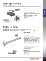
ENFORCER
SR-5201R
DOOR LOCK INTERFACE
SR-5203A
TIMING DOOR LOCK INTERFACE
SPECIFICATIONS FOR SR-5201R
Power: +12VDC
Contact Rating: 10 Amps
Lock/Unlock Timing: Controlled By Alarm
SPECIFICATIONS FOR SR-5203A
Power: +12VDC
Contact Rating: 30 Amps
Current Drain: 2.5mA (standby)
Lock/Unlock Pulse Length:
Lock (Grey wire loop):
Uncut: 0.7 seconds
Cut: 3.5 seconds
NOTE: The above refers to the grey and brown wire loops found on the SR-5203A for systems without
timed door lock/unlock outputs.
Unlock (Brown wire loop):
Uncut: 0.7 seconds
Cut: 3.5 seconds
SECO-LARM
®
U.S.A., INC.
16842 Millikan Avenue
Irvine, California 92606
FILE: MTR5203c.Pmd 10/11/13
®
COLOR-CODED WIRE FUNCTIONS
COLOR FUNCTION
GREY Lock signal from the alarm
RED +12VDC
BROWN Unlock signal from the alarm
GREEN Relay lock common
GREEN/PURPLE Relay lock (N.O.)
GREEN/WHITE Relay lock (N.C.)
BLUE Relay unlock common
BLUE/PURPLE Relay unlock (N.O.)
BLUE/WHITE Relay unlock (N.C.)
BLACK Chassis ground (SR-5203A only)
GREY WIRE LOOP Programs lock pulse timer (SR-5203A only)
BROWN WIRE LOOP Programs unlock pulse timer (SR-5203A only)

INTRODUCTION
The SR-5203A and SR-5201R are interfaces designed to allow SECO-LARM’s Enforcer series of RF
remote control alarms to lock and unlock a car’s doors automatically when the alarm is armed and
disarmed. With the convenience of automatic door locking and unlocking, the user need not fumble with
keys to get into or leave the car. It makes manual door locks obsolete!
The SR-5203A and SR-5201R connect to almost any factory-installed door lock actuators, including the
vacuum-operated units found in Mercedes Benz cars which require longer timers. In addition, aftermarket
actuators such as the SR-5202-ME from SECO-LARM can be installed in cars without factory actuators
and then connected to the SR-5203A or SR-5201R.
WARNING
While every attempt has been made to make this manual as clear as possible, installation of the
SR-5203A and SR-5201R is not an easy task. DO NOT ATTEMPT TO INSTALL THE SR-5203A OR
SR-5201R WITHOUT FIRST THOROUGHLY FAMILIARIZING YOURSELF WITH THIS MANUAL.
IMPROPER INSTALLATION CAN DAMAGE THE SR-5203A OR SR-5201R AND/OR THE CAR’S
ELECTRICAL CIRCUITRY. ALSO, MAKE SURE YOU UNDERSTAND THE DIFFERENCE BETWEEN THE
SR-5203A AND SR-5201R TO ENSURE THE CORRECT MODEL IS USED FOR EACH PARTICULAR
ALARM.
IMPORTANT
The information and specifications printed in this manual are current at the time of publication. However,
the SECO-LARM policy is one of continual development and improvement. For this reason, SECO-LARM
reserves the right to change specifications without notice. Also please note that this manual explains certain
accessory items that do not come as standard equipment with this unit. The information regarding these
accessories was included to help make the addition of such items as simple as possible.
Copyright © 1999 SECO-LARM. All rights reserved. This material may not be reproduced or copied, in
whole or in part, without the written permission of SECO-LARM.
The SR-5203A and SR-5201R are patent pending.
WHY TWO MODELS OF DOOR LOCK INTERFACES?
This manual explains in great detail the installation and use of both the SR-5203A and SR-5201R door
lock interfaces. As you read through this manual, you will notice that the installation and use of both
interfaces are virtually the same. So why are there two different models?
The major difference between the SR-5203A and SR-5201R is that the SR-5203A includes built-in lock
and unlock timers with grey and brown wire loops to control the timing duration. The SR-5201R uses the
timer built into the Enforcer alarm brain, and so has no wire loops.
FOR NON-SECO-LARM ALARMS
If you wish to add a SECO-LARM power door lock interface to a non-SECO-LARM alarm, make sure that
you can identify a negative (ground) output coming from the alarm when it is armed, and a separate
negative (ground) output when it is disarmed. If those outputs are timed specifically for lock and unlock use,
then use the SR-5201R interface. If those outputs are not timed, then use the SR-5203A interface.
HOW THIS MANUAL IS ARRANGED
This manual covers the installation of both the SR-5203A and SR-5201R. Since the installation of the two
is similar, only occasional references to their differences need be noted. The SR-5203A connection
diagrams are used, but that will make no difference in the installation of either unit.
Sections 1 through 6 of this manual give general information regarding operation and installation of the SR-
5203A and SR-5201R. Sections 7 through 14 give detailed installation procedures according to the type
of door locks found in the car you are working on.
VERY, VERY IMPORTANT
Even though installation and use of both the SR-5203A and SR-5201R are similar, the two units are not
interchangeable. This cannot be emphasized enough. If you are installing an alarm system without door
lock and unlock outputs, you must use the SR-5203A interface. If you are installing an alarm with timed
door lock and unlock outputs, you must use the SR-5201R interface. Using the wrong interface with a
particular alarm will have unpredictable consequences, including possible damage to the alarm brain, door
lock interface, or even the car’s power door lock/unlock system.
INSTALLING THE SR-5203A OR SR-5201R
(Note that installation is virtually the same for both units)
DETERMINING WHICH LOCK/UNLOCK SYSTEM IS BEING USED
Factory-installed power door lock systems vary from car to car, but some cars may require aftermarket door
lock actuators. If you find a system not covered by this manual, please consult the automobile manufacturer
or a certified automotive electrician.
WHERE TO START
Before you start removing door panels or dissecting the under-dash wiring harnesses, please ask yourself the
following questions:
1. Does the car already have power door locks? This sounds simple, but many inexperienced installers
waste time trying to find the lock and unlock wires of cars without power door locks. If the car does not
have power door locks, then add aftermarket actuators as shown on the reverse of this page.
2. Does a car with power door locks have an actuator in the driver’s door? Test the door lock system to see
if the driver’s door has an actuator. If manually locking and unlocking the driver’s door also locks and
unlocks the passenger’s door, but there is no way to electrically lock or unlock the driver’s door, then the
driver’s door has no actuator. This is the case with most Volvos and older Mercedes. In this situation, an
actuator must be added to the driver’s door only (see the reverse page). Then connect only this new
actuator to the door lock interface. The interface will lock and unlock the new actuator, thus locking and
unlocking the other doors.
After determining that no actuators are needed, then examine the switch which causes every door to lock
and unlock. This may require removing a door panel (be careful— those panels are expensive), but this is
much easier than trying to find the right wire in the kick panel. However, it may be easier for experienced
installers to look under the kick panel.
If there are only 3 wires leading to the door lock control switch, then test for negative relay switching systems
first, since the majority of power door lock systems are of this type (including most Japanese and European
cars). If the system is not negative relay switching, then test for positive relay switching. If the system is
neither negative nor positive relay switching, then test for reversal and floating reversal switching.
TEST METERS VS. TEST LIGHTS
More and more cars are being equipped with low-voltage (often only +3VDC) electronics. If you connect a
test light to +12VDC, and accidentally touch a +3VDC wire, there is a very good chance you will destroy
some component and/or a $1,000 to $2,000 computer. Therefore, SECO-LARM strongly recommends a
test meter (VOM) for testing power door locks, as well as for all electrical testing purposes. Test meters
conduct less current than test lights, and so will not damage the automobile. WARNING! Use only the
voltage and/or resistance settings on your test meter when checking wire polarity. Using the Amperage
setting is the equivalent of creating a short between the two contact points.
This manual assumes you know how to use a test meter. If you do not, then learn how to use one before
proceeding with installation of the SR-5203A or SR-5201R.
IMPORTANT Before cutting any door lock switch wires, test each wire with a test meter three times— with
the door locks at rest, when they are locked, and when they are unlocked. Read the information for each
system and study the diagrams. SECO-LARM DOES NOT WARRANTY ANY ALARM, THE SR-5203A OR
SR-5201R, OR THE CAR AGAINST DAMAGE CAUSED BY IMPROPER INSTALLATION.
MOUNTING THE SR-5203A AND SR-5201R
1. Choose a place where the SR-5203A or SR-5201R can be mounted (such as under the dash near the
alarm brain), noting the following restrictions:
* The unit should be mounted completely out-of-sight. Its placement must not interfere with the normal
operation of the car’s other circuits or parts.
* The unit must not be mounted in such a place where it is exposed to extended air movements, such as
in front of the heater or air conditioner vents. DO NOT MOUNT IN THE ENGINE COMPARTMENT.
2. Make all connections to the SR-5203A or SR-5201R using 18-gauge or thicker wire. If lighter wire is
used, the doors may lock and unlock randomly. Solder all connections to ensure they will not become
loose due to road vibration.
3. DO NOT CONNECT THE RED WIRE OF THE SR-5203A OR SR-5201R TO THE SAME POWER
SOURCE THAT THE ALARM’S RED (POWER) WIRE IS CONNECTED. DO NOT CONNECT THE
BLACK WIRE OF THE SR-5203A TO THE SAME GROUND SOURCE THAT THE ALARM’S BLACK
(GROUND) WIRE IS CONNECTED. This will prevent a major source of interference between the door
lock interface and the alarm brain.

WIRE CONNECTIONS FOR DOOR LOCK/UNLOCK (SR-5203A & SR-5201R)
Door Lock System #1: RELAY SWITCHING TO FACTORY ACTUATORS
FACTORY
SWITCHING
RELAY
FACTORY
DOOR LOCK
ACTUATORS
FACTORY
LOCK/UNLOCK SWITCH
May be (+) or (-)
see the table below.
CAR STYLE
MOST GM CARS
MOST JAPANESE CARS
LOCK WIRE
LIGHT BLUE
UNLOCK WIRE
BLACK
+12VDC
GROUND
Door Lock System #2: POSITIVE REVERSAL SWITCHING TO FACTORY ACTUATORS
(MOST FORDs, CHRYSLERs, AND GM TRUCKS)
MOST CHRYSLERs:
ORANGE -- LOCK
PINK -- UNLOCK
MOST GM TRUCKS:
LIGHT BLUE -- LOCK
BLACK or BLACK/WHITE-- UNLOCK
MOST FORD CARS:
PINK/GREEN -- LOCK
PINK/YELLOW - UNLOCK
MOST FORD TRUCKS:
BLACK/ORANGE -- LOCK
PINK/GREEN -- UNLOCK
FACTORY
DOOR LOCK ACTUATORS
FACTORY LOCK/
UNLOCK SWITCH
+12VDC HOT
Door Lock System #3: AFTERMARKET DOOR LOCK ACTUATORS
If the car does not have power door locks, install aftermarket actuators according to the manufacturer's
instructions. SECO-LARM model SR-5202-ME door lock actuators are recommended.
If the car is equipped with central door locks and with only one switch in the driver's door, it may be necessary
to add another actuator.
AFTERMARKET
DOOR LOCK ACTUATORS
SECO-LARM SR-5202-ME
CUT
X
X
CUT
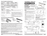
SETTING THE LOCK/UNLOCK PULSE LENGTH
(SR-5201R)
The door lock timing is controlled by your alarm. Please consult your alarm installation manual.
(SR-5203A)
1. If the car uses electric door lock actuators or motors (almost all cars do),
then: do not cut the grey or brown wire loops.
This will give a lock/unlock pulse length of 0.7 seconds required for electric locks.
2. If the car uses vacuum-operated door lock motors (like newer Mercedes Benz or Audi), then:
CUT BOTH the grey and brown wire loops.
3. The grey and brown wire loops on the SR-5203A must both be cut, or must both be left uncut. Do
not cut one loop and leave the other uncut.
WARNING: WHEN CONNECTING TO ELECTRIC (AS OPPOSED TO VACUUM)
DOOR LOCK ACTUATORS, IF THE GREY AND BROWN WIRE LOOPS ARE CUT,
THE DOOR LOCK ACTUATORS WILL BURN OUT.
GREY
TO ENFORCER
GREY WIRE
GREY LOOP
UNCUT: 0.7SEC.
CUT: 3.5SEC.
BLUE UNLOCK
GREEN/WHITE
GREEN/PURPLE
GREEN LOCK
BLUE/WHITE
BLUE/PURPLE
RED
+12VDC
BLACK
GROUND
BROWN LOOP
UNCUT: 0.7SEC.
CUT: 3.5SEC.
BROWN
TO ENFORCER
BROWN WIRE
AFTERMARKET ACTUATOR, OR
FACTORY SWITCHING RELAY, OR
DOOR LOCK/UNLOCK SWITCH
NOTE:
THERE ARE LOOPS &
BLACK WIRE ON
THE SR-5201R
CIRCUIT EQUIVALENCE FOR SR-5201R (Reference only)
GREEN/WHITE
GREEN/PURPLE
BLUE/WHITE
BLUE/PURPLE
RED
+12VDC
BROWN
TO ENFORCER
BROWN WIRE
GREY
TO ENFORCER
GREY WIRE
AFTERMARKET ACTUATOR, OR
FACTORY SWITCHING RELAY, OR
DOOR LOCK/UNLOCK SWITCH
BLUE UNLOCK GREEN LOCK
BROWN
GREEN/PURPLE
BLUE/PURPLE
BLUE
GREEN/WHITE
BLUE/WHITE
BLACK (SR-5203A ONLY)
RED
GREY
X
X
GREEN
BROWN
GREEN/PURPLE
BLUE/PURPLE
BLUE
GREEN/WHITE
BLUE/WHITE
BLACK (SR-5203A ONLY)
RED
GREY
GREEN
BROWN
GREEN/PURPLE
BLUE/PURPLE
BLUE
GREEN/WHITE
BLUE/WHITE
BLACK (SR-5203A ONLY)
RED
GREY
GREEN
+12VDC
CIRCUIT EQUIVALENCE FOR SR-5203A (Reference only)
+12VDC
ENFORCER 3-PIN CONNECTOR
ENFORCER 3-PIN
CONNECTOR
ENFORCER 3-PIN
CONNECTOR

FLOTAING
SYNC. DPDT
SWITCH
NOTE 2. SWITCH OUTPUT STATUS:
BEFORE CUTTING WIRE#6
NORMAL: NO OUTPUT
LOCK: +12VDC OUTPUT
UNLOCK: GROUND OUTPUT
AFTER CUTTING WIRE#6
NORMAL: NO OUTPUT
LOCK: NO OUTPUT
UNLOCK: GROUND OUTPUT
NOTE 1. SWITCH OUTPUT STATUS:
BEFORE CUTTING WIRE#3
NORMAL: NO OUTPUT
LOCK: GROUND OUTPUT
UNLOCK: +12VDC OUTPUT
AFTER CUTTING WIRE#3
NORMAL: NO OUTPUT
LOCK: GROUND OUTPUT
UNLOCK: NO OUTPUT
NOTE 3.
WHEN WIRE#1 IS CUT,
INSULATE BOTH WIRE
LEADS BY SEPARATELY
WRAPPING THE ENDS WITH
ELECTRICAL TAPE.
DOOR LOCK
ACTUATORS
NOTE 1.
NOTE 2.
NOTE 3.
HOT +12VDC
3
1
6
5
CUT
X
X
LOCK
UNLOCK
4
Door Lock System #5: FLOATING SWITCHING FACTORY SYSTEMS
INSTALLING AFTER-MARKET ACTUATORS
(SECO-LARM MODEL NO. SR-5202-ME)
Install the actuators according to the diagram below, noting the following:
1. Make sure that the actuator’s shaft pushes and pulls the door lock rod as straight as possible to prevent
damage to the actuator and to assure smooth operation.
2. The clamps to the door lock rod must be as tight as possible to prevent slipping when the actuators are
activated.
3. Use either screws or nuts and bolts to fix the actuator inside the door. The tension of each screw or nut
must be the same to prevent warping of the actuator.
4. The entire door lock mechanism must be free from any kinks or bends which would prevent free
movement. It is recommended to thoroughly clean the entire mechanism (not including the actuator) and
spray it with oil or silicon to ensure free movement.
5. Connect the after-market actuators to the SR-5203A or SR-5201R as shown in Doorlock System #3
above.
NOTE 1: Some cars have actuators built into every door except the driver’s door, so that when the driver’s
door is manually locked or unlocked, the other doors will also automatically lock or unlock. In this
case, a single SR-5202-ME may be added to the driver’s door. The SR-5203A or SR-5201R should
be connected to lock and unlock the SR-5202-ME only. The other doors will lock and unlock with
the driver’s door.
NOTE 2: The diagrams below may not be applicable to every car door.
WARNING: THE MOTOR OF THE SR-5202-ME WILL BURN OUT IF ABUSED. Therefore, do not
switch this unit between lock and unlock more than 10 times in a short period of time. Allow a
minimum of 10 seconds between each lock and unlock operation.
X
CUT
2
Door Lock System #4: SINGLE-WIRE SYSTEMS
A. SINGLE WIRE, POLARITY SWITCHING (MOSTLY MERCEDES BENZs)
GREEN/PURPLE
+12VDC
GREEN
BLUE/PURPLE
BLUE
GREEN/WHITE
BLUE/WHITE
B. SINGLE WIRE, SHUNT SWITCHING (SOME FORDS: 1992 PROBE)
This door lock system uses a single wire to activate the door locks. Applying an activated signal
on the activation wire causes the doors to unlock, and by removing the activated signal, the
doors will lock.
NOTE: If the correct wire is cut, the driver and front passenger switches will not lock or unlock any of
the doors. Once the correct wire is located, connect according to the diagram below.
ACTUATOR
CONTROL
MODULE
FACTORY
DOOR LOCK
ACTUATORS
FACTORY LOCK/
UNLOCK SWITCH
Ref. the table
shown below.
CUT
CAR STYLES
SOME FORD PROBES
SOME MAZDA MPVS
SOME NISSAN 300ZX & 240SX
ACTIVATION WIRES
GREEN/BLACK
GREEN/BLACK
ORANGE/BLACK
+12VDC
GROUND
GROUND
X
X
BLACK (SR-5203A ONLY)
RED
GREY
BROWN
BOTH WIRE LOOP CUT (SR-5203A)
GREEN/PURPLE
GREEN
BLUE/PURPLE
BLUE
GREEN/WHITE
BLUE/WHITE
BLACK (SR-5203A ONLY)
RED
GREY
BROWN
X
X
GREEN/PURPLE
+12VDC
GREEN
BLUE/PURPLE
BLUE
GREEN/WHITE
BLUE/WHITE
BLACK (SR-5203A ONLY)
RED
GREY
BROWN
ENFORCER 3-PIN CONNECTOR
ENFORCER 3-PIN
CONNECTOR
ENFORCER 3-PIN
CONNECTOR
/