Page is loading ...

Centralized Controller
AG-150A
AG-150A-A Instruction Book
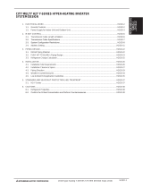
1. Safety precautions .............................................................. 1
2. Introduction ......................................................................... 2
3. Product features ................................................................. 3
4. Component names and display screen names................... 6
5. Initial Start up.................................................................... 13
5-1 Initial start up for a system without connection to an
Expansion controller (PAC-YG50ECA).................... 13
5-2 Initial start up for a system with connection to an
Expansion controller (PAC-YG50ECA).................... 15
5-3 Connecting multiple AG-150A to a system with
connection to Expansion controllers ........................ 18
6. User operation .................................................................. 23
6-1 Operation condition monitoring................................ 24
6-2 Operation setting/Prohibition setting from local
remote controller...................................................... 27
6-3 Setting Schedules.................................................... 32
6-4 Checking the List of Malfunctioning Units................ 43
6-5 Checking the List of Units with a Triggered
Filter Sign................................................................. 45
6-6 Checking the Malfunction Log ................................. 46
7. Initial Settings ................................................................... 47
7-1 Bringing up the settings screen ............................... 47
7-2 Locking the screen................................................... 50
7-3 Setting the Current Date and Time .......................... 51
7-4 Register the license ................................................. 52
7-5 Setting the Basic Information................................... 53
7-6 Network Setting ....................................................... 55
7-7 Group Setting........................................................... 59
7-8 Interlocked Setting ................................................... 63
7-9 Block Setting............................................................ 65
7-10 Floor Layout Setting................................................. 67
7-11 Checking the refrigerant systems ............................ 72
7-12 Advanced settings ................................................... 73
8. Function 1 ......................................................................... 74
8-1 Outside temperature interlock function.................... 74
8-2 Night setback function ............................................. 77
9. User Setting ...................................................................... 80
9-1 Setting the Maintenance User ................................. 80
9-2 Setting the Building Manager................................... 80
10. Maintenance screen ......................................................... 82
10-1 Copying the data to a USB memory ........................ 82
10-2 Reading setting data from USB memory ................. 86
10-3 Adjusting the touch panel ........................................ 87
11. Cleaning the touch panel .................................................. 88
12. External input/output function ........................................... 89
12-1 External input function ............................................. 89
12-2 External output function........................................... 90
13. LAN connection function................................................... 90
14. Specifications.................................................................... 91
15. Error code list.................................................................... 92
15-1 M-NET error code .................................................... 92
15-2 EC line error code.................................................... 96
CENTRALIZED CONTROLLER AG-150A
Air-conditioner Control System
WT05369X12
Ver. 2.70
Before using the controller, please read this Instruction Book carefully to ensure proper operation.
Retain this manual for future reference.
WT05369X12.book Page 1 Friday, July 22, 2011 9:00 AM

– 1 –
1. Safety precautions
Before using the controller, read the Safety Precautions section carefully to ensure proper operation.
These safety precautions must be observed by anyone who operates the centralized controller.
Keep the Instruction Book and Installation Manual for future reference. Make sure both manuals are passed on to any
future air condition system users.
WARNING
This symbol indicates that failure to follow the instructions exactly as stated poses the risk of
serious injury of death.
CAUTION
This symbol indicates that failure to follow the instructions exactly as stated poses the risk of
injury or damage to the controller.
WARNING
CAUTION
The unit must be installed by a dealer or technical
representative.
Improper installation by an unqualified person may result in
electric shock and fire.
Install in a location that is strong enough to withstand
the weight of the unit.
A weak installation area may cause the unit to fall down,
resulting in a personal injury.
Only use specified cables. Securely connect each
cable so that the weight of the cable is not applied to
the connectors.
Loose or improper connections may result in heat
generation or fire.
If any abnormality is noticed (e.g., burning smell), stop
the operation, turn off the power supply, and contact
your dealer or technical representative immediately.
Continuing the operation may result in damage to the
controller, electric shock, or fire.
Ask your dealer or an authorized technician to move or
reinstall the controller.
Improper installation may result in an electric shock or fire.
Controllers must be disposed of properly.
Contact your dealer for proper disposal procedures.
Do not attempt to modify or repair the controller.
Modification or improper repair may result in electric shock
or fire. Consult your dealer when repairs are necessary.
Stop the operation immediately and notify your dealer
if an error code is displayed and the controller does
not operate, or when any abnormality is noticed.
Continuing the operation may result in damage to the
controller or fire.
Do not install the controller where there is a risk of
leaking flammable gas.
If the leaked gas accumulates around the controller, it may
ignite and cause an explosion.
Do not wash the unit with water.
Doing so may cause an electric shock or malfunction.
Do not use the controller for specialized applications.
This product is designed exclusively for use with the
MITSUBISHI ELECTRIC building air conditioning control
system. The use of this product with other air-conditioning
management systems or for other purposes may result in
malfunctions.
Do not spray insect sprays or sprays with flammable
propellants to the controller.
To avoid the risk of fire or explosion, do not place
flammable sprays near the controller or spray them directly
on the controller.
To avoid the risk of electric shock or damage to the
controller, do not touch the touch panel or USB storage
device connector with wet hands.
Do not use the controller in an environment high in oil,
steam, or sulfuric gas.
These substances may have adverse effects on the
performance of the controller or damage its parts.
To avoid the risk of electric shock or damage to the
controller, do not press the touch panel with sharp
objects.
Operate the controller within the temperature range
specification.
The use of controller outside of its specification may result
in serious damage to the controller. Be sure to check the
temperature range specification in the Instruction Book.
Use a security device such as a VPN router when
connecting the AG-150A or AG-150A-A to the Internet
to prevent unauthorized access.
If no security devices are installed, the operation settings
may be changed by an unauthorized person without the
knowledge of the user.
To reduce the risk of malfunction, do not apply impact
or vibration after installation.
WT05369X12.book Page 1 Friday, July 22, 2011 9:00 AM

– 2 –
2. Introduction
The terms “Group,” “Block,” and “EC” used in this manual are defined as follows:
Group: Group is a group of air conditioning units and controllers and is the smallest unit that the AG-150A and AG-150A-A can control.
The maximum number of units and controllers that each group can contain is 16.
Block: Block is a group of groups. Energy-save and peak-cut settings are made for each block.
EC: EC is short for Expansion Controller (PAC-YG50ECA).
Hereinafter, AG-150A and AG-150A-A, unless otherwise specified, will be called "AG-150A".
WT05369X12.book Page 2 Friday, July 22, 2011 9:00 AM

– 3 –
3. Product features
The controller described in this manual is a centralized controller that can be operated over the Web.
Any connected air conditioning systems can be operated or monitored directly from the controller or over the Web using
browser software.
Refer to the Web browser operation manual (separate volume) for how to use this functions.
Function Description
Number of
controlled unit
Indoor unit, Ventilation unit
(LOSSNAY and OA handling
unit), DIDO controller, Air To
Water (PWFY)
Up to 150 units are connectable (including the interlocked units) *2
By connecting three PAC-YG50ECA Expansion controllers (sold separately), a maximum
of 150 units of equipments can be controlled. Each DIDO controller (PAC-YG66DCA)
contact counts as one unit.*4
Number of units in one group
(indoor, independent OA
processing unit, or LOSSNAY)
1-16 units (Indoor unit, independent OA processing unit, ventilation system (LOSSNAY),
and DIDO controller cannot be registered to the same group.)
Number of remote controllers in
one group
1-2
Number of system controllers
in one group
0-4 (including the number of remote controller in one group)
Number of interlocked
LOSSNAY units
• Number of LOSSNAY units that can be interlocked with an indoor unit: 1
• Number of indoor units that can be interlocked with a LOSSNAY unit: 16
User Operations Function
Operation
*1
ON/OFF The ON/OFF operation can be performed as a collective, per group, or per block.
Operation mode
The switch operation for the operation mode setting can be performed as a collective, per
group, per block, per floor, or per building. (Available modes depend on the model of
indoor units.)
[Selectable operation mode for the indoor unit]
COOL/DRY/FAN/AUTO/HEAT
[Selectable operation mode for the independent ventilation]
HEAT RECOVERY/BY-PASS/AUTO
[Selectable operation mode for Air To Water (PWFY)]
HEATING/HEATING ECO/HOT WATER/ANTI-FREEZE/COOLING
Fan speed
Up to four fan speeds are available. Fan speed can be changed collectively, or for each
group or block of indoor units. (The number of available fan speeds depends on the indoor
model (2 speeds, 3 speeds, 4 speeds, and Auto). “Auto” is available only on the models that
support that function.)
Temperature setting
Temperature setting can be performed collectively, per group, or per block.
[Setting temperature range for air conditioner]
Cool (Dry) operation: 19 ~ 30°C / 67 ~ 87°F
Heat operation: 17 ~ 28°C / 63 ~ 83°F
Auto operation: 19 ~ 28°C / 67 ~ 83°F
[Setting temperature range for Air To Water (PWFY)]
[Booster unit]
*3
Heating: 30 ~ 50°C/87 ~ 122°F
Heating ECO: 30 ~ 45°C/87 ~ 113°F
Hot Water: 30 ~ 70°C/87 ~ 158°F
Anti-freeze: 10 ~ 45°C/50 ~ 113°F
Cooling: Invalid
[Water HEX unit]
*3
Heating: 30 ~ 45°C/87 ~ 113°F
Heating ECO: 30 ~ 45°C/87 ~ 113°F
Hot Water: Invalid
Anti-freeze: 10 ~ 45°C/50 ~ 113°F
Cooling: 10 ~ 30°C/50 ~ 87°F
Air direction and swing
operation
Vertical air flow directions (5 directions), auto setting, and swing setting can be changed
collectively, or for each group or block of indoor units. (Available air flow directions depend
on the model. [5 air flow directions and AUTO] are available only on the models that support
those settings.
Operating/stopping interlocked
LOSSNAY units
Interlocked LOSSNAY units (if any) can be operated (at High or Low) or stopped collectively
or for each group or block of indoor units. (Ventilation mode cannot be selected for the
interlocked LOSSNAY units.)
Schedule
Group is the smallest unit to which a weekly schedule can be assigned. The same schedule
can be applied collectively, or to each group, groups in a block, or groups on a floor.
• Up to 24 events can be scheduled for each day.
• “ON/OFF”, “Operation mode”, “Temperature Setting”, “Fan Speed Setting”, “Vane
Setting”, and “Prohibition of operation from local remote controller” can be timer-
controlled.
If a license is registered
• Two types of weekly schedule patterns (summer and winter) are available.
• Five operation patterns (A-E) can be set for each year, up to 50 days can be allocated to
each pattern.
• When Optimized startup schedule is set, the operation starts so that the preset
temperature is reached at the preset time.
Prohibit local remote control
Operation of certain functions from the local remote controllers can be prohibited
collectively or for each group or blocks of indoor units.
(Applicable functions: ON/OFF, operation mode, temperature setting, filter sign, Water
circuit sign (Air To Water (PWFY)))
Filter sign reset Filter sign can be reset for each group or block of indoor units.
Water circuit sign reset
(Air To Water (PWFY))
Water circuit sign (Air To Water (PWFY)) can be reset for each group or block of indoor
units.
Error reset Resets the display of error.
Error history reset Resets the error history (unit error, communication error).
External input
Connects to an external input/output device that stops the units in an emergency, run or
stop the units, permit or prohibit the operation of units collectively. Requires an external
input/output adapter (sold separately).
WT05369X12.book Page 3 Friday, July 22, 2011 9:00 AM

– 4 –
User Operations Function
Monitor
*1
ON/OFF (system)
The ON/OFF indicator lamp (LED) indicates if one or more groups or all the groups in the
system are stopped.
Operation status of each group
in the system
Operation status (ON/OFF), operation mode, fan speed, temperature setting, air flow
direction, operation status (ON/OFF) of interlocked units is displayed.
Filter sign Indicates that the filters on the units in a given group is due for cleaning.
Water circuit sign
(Air To Water (PWFY))
Indicates that the circulating water circuit in a given group is due for replacement.
Local operation prohibition
Displays the functions that the controller forbids or the functions that are forbidden by High-
level equipment.
Error
The address of the unit in error, error code, and the address of the unit that detected the
error will appear.
Error history monitor
Up to 384 errors can be stored in memory. (128 errors per AG-150A or Expansion controller
(64 unit errors, 64 communication errors))
External output
Outputs signals (run/stop, error) to an external device. Requires an external input/output
adapter (sold separately).
Initial Settings
Operation
*1
Date and time This function is used to set the current date/time and daylight savings time.
License This function is used to register license.
Unit Info.
This function is used to set unit name, ID number, connection or non-connection of
Expansion controller, brightness of the LCD, sound volume, date format, time format,
temperature unit, and display language, test run availability, screen lock and room
temperature availability.
Network
This function is used to set the IP address, subnet mask address, and gateway settings for
the LAN and also to set the address, K-transmission converter address, local control
prohibit settings, and external input settings for the M-NET; and the Expansion controller
settings.
Advanced Allows the Master/Sub clock setting to be made.
Groups
This function is used to register indoor units, LOSSNAY units , DIDO controller (PAC-
YG66DCA), Air To Water (PWFY), remote controllers, and lower-level system controllers to
a group.
Blocks This function is used to register a group to a block.
Interlock This function is used to interlock the operation of indoor units and LOSSNAY units.
Floor Layout
This function is used to make the basic settings for the floor layout and display position of
the groups.
Monitor
*1
Refrigerant system
configuration confirmation
Allows the user to see which indoor units are connected to each outdoor unit.
Operation
*1
Ext Temp Interlock Control level of outside temperature interlock function can be set for each group.
Setback Control time and upper/lower limit temperature can be set for setback function.
User Info
Maintenance User Allows the maintenance user name and password to be set.
Building Manager Allows the building manager name, password, function enable/disable settings to be made.
Data utility
Copying data to a USB memory
drive
The setting data (Initial setting and user info) and the operation data (charge parameter and
electric energy data) can be copied to a USB memory drive.
Reading data from a USB
memory drive
The setting data (Initial setting and user info) can be read from a USB memory drive.
Touch panel calibration The touch position on the touch panel can be adjusted.
Other
Data
back-up
Connection/Interlock
Information
Group setting information and interlock setting information are retained, even if power is
turned off.
Error history Retained, even if power is turned off.
Schedule data Schedule information of each group is retained, even if power is turned off.
Current time
Current time is retained by the built-in capacitor for a week, even if power is turned off.
(It takes approximately a day to fully charge the built-in capacitor. There is no need to
replace the capacitor.)
Saving the data on a USB drive
The initial setting data, user info, and operational data (charge parameters, power
consumption) can be stored to a USB memory.
Reading data from USB
memory
Initial setting data can be read from USB memory.
Device
maintenance
Screen lock function
The screen can be locked to prevent access until a valid user name and password are
entered.
Touch panel cleaning Touch panel is locked and can be cleaned.
Time synchronization
Clocks on the controllers and units that are under the control of the main controller are
synchronized once a day (applicable only to the ones that support this function).
Function Description
WT05369X12.book Page 4 Friday, July 22, 2011 9:00 AM

– 5 –
*1: The item and range that can be operated or monitored depend on the function of the indoor unit.
*2: The maximum number of the controllable units varies, depending on the number of channels used by DIDO controllers.
*3: “Air To Water (PWFY)” on the AG-150A screen indicates Booster unit group and Water HEX unit group.
*4: Up to 6 general equipments can be connected to each DIDO controller (PAC-YG66DCA).
* Main and Sub system controllers
The controller described in this manual can only be used as a Main controller, not as a Sub controller.
• Main system controller (Main SC)
Main SC refers to a controller that controls all other system controllers, including the units they control.
If a given system has only one system controller, that controller becomes a Main controller.
Group settings and interlock settings can only be made from a Main controller.
• Sub system controller (Sub SC)
Sub controller refers to a system controller that is controlled (including the units it controls) by a Main system controller.
AG-150A
M-NET Gateway
management range
Another system controller
management range
Unit
Unit
Unit
Unit
When AG-150A controls another system controller or when
the system contains only AG-150A:
AG-150A is set as the main system controller.
*AG-150A performs the group setting in this configuration.
management range
Management range
of AG-150A
When AG-150A is controlled by another system controller:
(Example: MJ-300Gateway)
AG-150A is set as the sub system controller.
*The group setting is performed by main system control-
ler.
NOTE:
The following group setting cannot be performed.
Unit groups which are not under the management of the main controller and are managed by the sub system
controller.
A common group is managed by mode than two main controllers.
A sub system controller which exceeds the management range of the main system controller of two or more.
Main system
controller
Group Group Group
Group Group Group
Sub system
controller
Main system
controller 1
Main system
controller 2
Group GroupGroup Group
Sub system
controller
Main system
controller 2
Main system
controller 1
WT05369X12.book Page 5 Friday, July 22, 2011 9:00 AM

– 6 –
4. Component names and display screen names
Screenshots of screen, their names, and the sequence they appear in are shown below.
• Screen that normally appears
* Normally, the screen remains black. The backlight turns on when the touch panel is touched and stays on while the user is operating
the touch panel. The backlight goes off after 10 minutes of non-operation.
* When an error occurs, the backlight turns on regardless of whether the user is operating the touch panel.
CENTRALIZED CONTROLLER AG-150A
Power indicator (AG-150A)
Not lit ... Power is turned off.
Lit ........ Power is turned on.
ON/OFF indicator lamp (LED) (system)
Displays the operation status of the connected equipment
Not lit.......All groups are stopped.
Lit ............One or more groups of the units are ON. (not
including the general equipments connected to
PAC-YG66DCA)
Blinking ...Indicates that an error occurred.
(including all connected equipments)
Display/Touch panel
Note:
Before using the AG-150A, remove
the protective sheet on the surface
cover.
CAUTION
If the protective sheet is left on the
screen, the sheet may stick to the
LCD and cause malfunctions.
USB port
Monitor/Operation
Schedule settings
Status List
Log
Initial
Settings
User
Info
Main operation screen
Touch
[User Info]
Touch
[Initial Settings]
Touch [ ]
Touch [ ]
Touch
[Function1]
Touch 1,2,3,4
Touch
[Cancel]
Maintenance
Touch
[Maintenance]
Touch
[User Info]
Touch
[Initial Settings]
Touch
[Maintenance]
Screen Lock
Tou c h
[]
Touch Panel CleaningLogin
Touch [ ]
Function1
Tou c h
[Function1]
Touch
[Login]
Setting change screen
WT05369X12.book Page 6 Friday, July 22, 2011 9:00 AM

– 7 –
<Initial Settings>
Important
• If nothing appears on the display after touching the touch panel several times, the LCD backlight may be damaged. Since continued
use may cause malfunctions, stop the operation, and contact the service center.
• Touching two points simultaneously will be interpreted as pressing a different point. To avoid malfunctions, only touch one point at a
time.
Login(P47)
Touch
[Login]
Advanced settings screen (P73)
Date and time (P51) Unit Info. (P53)License (P52)
Groups (P59)Network (P55)
Interlock (P63) Floor Layout (P67)Blocks (P65)
The above nine initial setting screens can be accessed from the sub menu.
System View (P72)
WT05369X12.book Page 7 Friday, July 22, 2011 9:00 AM

– 8 –
<Monitor/Operation>
Air conditioning system operation screen (P27)
Floor layout (detailed icons) (P24)
Floor layout (simplified icons) (P25)
Block display (P25)
Login (P47)
Touch
[]
Touch
[]
Tou c h
[]
WT05369X12.book Page 8 Friday, July 22, 2011 9:00 AM

– 9 –
<Schedule Settings>
• Setting the schedule without a license registration
Weekly schedule screen(P34)
Schedule setting screen (block display) Weekly(P33)
Schedule setting screen (floor layout) Weekly(P32)
Schedule setting screen (air conditioning units)(P35)
Login(P47)
Touch
[]
WT05369X12.book Page 9 Friday, July 22, 2011 9:00 AM

– 10 –
<Schedule Settings>
• Setting the schedule with a license registration
Annual schedule screen(P39)
Current day schedule screen(P41)
Login(P47)
Schedule setting screen (block display)
Weekly 1, Weekly 2(P37)
Schedule setting screen (floor layout)
Weekly 1, Weekly 2(P37)
Schedule setting screen (block display)
Current day/annual(P39)
Schedule setting screen (floor layout)
Current day/annual(P39)
Season setting screen(P39)
Weekly schedule screen(P34)
Schedule setting screen (air conditioning units)(P35)
Annual schedule pattern setting screen(P39)
Touch [ ]
Tou c h
[]
WT05369X12.book Page 10 Friday, July 22, 2011 9:00 AM

– 11 –
<Status List>
<Log>
Malfunction(P43)
Filter sign(P45)Login(P47)
Touch
[]
Touch
[]
Tou c h
[Filter Sign]
Touch
[Malfunction]
Unit error(P46)
Communication error(P46)Login(P47)
Tou c h
[Communication Error]
Touch
[]
Touch
[Unit Error]
Touch
[]
WT05369X12.book Page 11 Friday, July 22, 2011 9:00 AM

– 12 –
<Function 1>
<User Info>
<Maintenance>
Touch
[Setback]
Tou c h
[Ext Temp Interlock]
Ext Temp Interlock(P74) Setback(P77)
Touch
[Building Manager]
Tou c h
[Maintenance User]
Maintenance User(P80) Building Manager(P80)
Touch
[Touch Panel Calibration]
Tou c h
[Data Utility]
Data Utility(P82) Touch Panel Calibration(P85)
Calibration(P85)
Touch
[Start Calibration]
Calibration completed
or
No operation for one minute.
WT05369X12.book Page 12 Friday, July 22, 2011 9:00 AM

– 13 –
5. Initial Start up
5-1 Initial start up for a system without connection to an Expansion controller
(PAC-YG50ECA)
After the power is turned on, the language selection screen will appear.
Select the language to be used for display, and then touch [OK].
Note: It will take approximately 20 seconds for the display to appear after
the power is turned on.
When the language is selected, the Date and Time setting screen will
appear. Set the date and time. (Refer to Section 7-3 for the details on how
to set the date and time.)
* The initial setup sequence does not set the date and time correctly. Be
sure to manually set the correct date and time.
* Touch the [Save Settings] button to reflect the changes.
Touch [Unit Info]
After setting the date and time, touch the [Unit Info.] tab and set the Name
and Unit ID. Be sure to set the Expansion Controller setting to “Do not use.”
(Refer to Section 7-5 for the details on how to set the Name and Unit ID.)
Touch [Network]
After making the unit settings, touch the right arrow to show the [Network]
tab and touch it. Set the IP address and M-NET address. (Refer to Section
7-6 for the details on how to set the IP address and M-NET address.)
Touch [Groups]
WT05369X12.book Page 13 Friday, July 22, 2011 9:00 AM

– 14 –
After making the network settings, touch the [Groups] tab, and make the
settings. (Refer to Section 7-7 for the details on how to make the group
settings.)
Make other settings such as block settings and interlocked LOSSNAY
settings. Refer to appropriate sections in Chapter 7 on how to make the
settings.
When the above settings have been made, the initial settings are
completed.
Touch the on the top right hand of the screen to go into the [Operation/
Monitor] screen.
Configure the floor layout on the [Floor Layout] screen if necessary.
* When the unit is started up again, the [Operation/Monitor], instead of the
Initial Settings screen, will appear. To change certain settings, refer to
Section 7-1 Calling up the initial setting screen to change the settings.
After moving to the [Operation/Monitor] screen, the startup screen will
appear.
Startup takes a maximum of five minutes after the message appears. (It
takes about two to three minutes when no communication errors occur.)
WT05369X12.book Page 14 Friday, July 22, 2011 9:00 AM

– 15 –
5-2 Initial start up for a system with connection to an Expansion controller (PAC-YG50ECA)
After the power is turned on, the language selection screen will appear.
Select the language to be used for display, and then touch [OK].
Note: It will take approximately 20 seconds for the display to appear after
the power is turned on.
Enter the unit name and ID on the Unit Info screen. Set the Expansion
Controller setting to “Use.”
(Refer to Section 7-5 for the details on how to set the Name
and Unit ID.)
Touch [Network]
When the unit settings have been completed, touch the right arrow to bring
up the [Network] screen, and touch [Network]. Select the [AG-150A] tab,
and set the IP address for the AG-150A.
Select the Expansion controller (EC1-EC3) whose settings are to be made
from the tab menu. Check that the DB No. on the AG-150A itself and the
DB No. of the Expansion Controller match. (The DB No. for the AG-150A
can be found on the back of the controller, on the package box, or on the
LCD. Refer to Section 7-1 (P 47) for how to confirm the DB No. on the LCD.
The DB No. for the Expansion controller can be found at the top of the
Expansion controller or on the package box.)
Touch [ ]
If the DB numbers match, make the IP address and M-NET address
settings for each. (Refer to Section 7-6 (P 55) for the details of how to make
the settings.)
* Consult your dealer if the DB numbers do not match.
* IP address and M-NET address cannot be set at the same time.
Save the IP address setting first, and then save the M-NET address
setting.
Touch [Groups]
WT05369X12.book Page 15 Friday, July 22, 2011 9:00 AM

– 16 –
After the network settings have been made, touch [Groups], select the EC
number from the tab menu, and make the group settings for each EC.
* The settings for the units that are connected to a different Expansion
controller cannot be made.
(Refer to Section 7-7 for the details of how to make the settings.)
Make other settings such as block settings and interlocked LOSSNAY
settings. Refer to appropriate sections in Chapter 7 on how to make the
settings.
Configure the floor layout on the [Floor Layout] screen if necessary.
* When the unit is started up again, the [Operation/Monitor], instead of the
Initial Settings screen, will appear. To change certain settings, refer to
Section 7-1 Calling up the initial setting screen to change the settings.
The Date and Time setting screen will appear. Set the date and time. (Refer
to Section 7-3 for the details on how to set the date and time.)
* To synchronize the time with the Expansion controllers, be sure to
manually set the correct date and time.
* Touch the [Save Settings] button to reflect the changes.
When the above settings have been made, the initial settings are complete.
Touch the on the top right hand of the screen to go into the [Operation/
Monitor] screen.
WT05369X12.book Page 16 Friday, July 22, 2011 9:00 AM

– 17 –
After moving to the [Operation/Monitor] screen, the startup screen will
appear.
Startup takes a maximum of five minutes after the message appears. (It
takes about two to three minutes when no communication errors occur.)
WT05369X12.book Page 17 Friday, July 22, 2011 9:00 AM

– 18 –
5-3 Connecting multiple AG-150A to a system with connection to Expansion controllers
Multiple AG-150A or other controllers can be connected to an air conditioning system, and each controller can control and monitor the
system.
Note that the number of connectable units and the software version is limited.
If the software version is unsupported, update the software version of the controllers.
(1) Restrictions on the number of connectable units
The total number of AG-150A should be three or less.
(2) Restrictions on the software version
(3) Restrictions on the DB No.
Controllers with different DB No. cannot be connected to each other.
(4) Miscellaneous restrictions
• Controllers such as AG-150A connected to a system must have the same settings for the settings such as Group or Interlocked
ventilation (LOSSNAY).
Different settings for the settings such as Group or Interlocked ventilation (LOSSNAY) cannot be made in a system.
• When connecting a general equipment using a DIDO controller (PAC-YG66DCA), register a group to each AG-150A connected to
a system.
Use only one AG-150A to make group settings for other units.
• When multiple AG-150A controllers are connected to a system, the following functions should be used only on one of the AG-150A
controllers : License registration, schedule settings, energy-save, peakcut, Night Setback Control, Interlock, External Temperature
Interlock, Night Mode Schedule, System-changeover, and Set temperature range limit.
• Icons that indicate schedule, energy-save mode, and setback mode enabled appear only on the AG-150A that controls these
modes.
System example when connecting multiple AG-150A
No. of connectable units
PAC-YG50ECA 3 units or less
AG-150A 1 unit 2 or 3 units
Software version
PAC-YG50ECA Ver. 1.00 or later Ver. 1.30 or later
AG-150A Ver. 2.00 or later Ver. 2.30 or later
Switching
HUB
AG-150A
24VDC
PAC-SC51KUA
AG-150A
PAC-SC51KUA
24VDC
PAC-SC51KUA
24VDC
AG-150A
PAC-YG50ECA
PAC-YG50ECA
PAC-YG50ECA
Outdoor unit
Outdoor unit
Outdoor unit
Indoor unit
Indoor unit
Indoor unit
M-NET
M-NET
M-NET
M-NET
M-NET
M-NET
M-NET
MA remote controller
MA remote controller
MA remote controller
LOSSNAY
unit
LOSSNAY
unit
LOSSNAY
unit
LOSSNAY
unit
LOSSNAY
unit
LOSSNAY
unit
LOSSNAY
unit
LAN
WT05369X12.book Page 18 Friday, July 22, 2011 9:00 AM

– 19 –
Shown below is how to connect two or more AG-150A controllers to a system. Refer to the respective manual for more information about
how to connect other types of controllers.
(5) Make the settings (e.g., IP address) for the Expansion controller network, and switch on the power.
Refer to section 5-1 “IP address and network settings” in the Installation/Instructions Manual.
(6) Switch on the power to the AG-150A (PAC-SC51KUA), and start the initial setting process.
Make the initial settings for each AG-150A.
1st AG-150A (Master) 2nd and subsequent AG-150A units
(7) Select the display language. (7) Select the display language.
(8) Make the unit information settings. (8) Make the unit information settings.
Set the Use/Do not use setting for the Expansion controller to
“Use.”
Set the Use/Do not use setting for the Expansion controller to
“Use.”
(9) Make the network settings for the AG-150A. (9) Make the network settings for the AG-150A.
* Changing and saving the network setting will restart AG-150A,
and the login screen will appear.
WT05369X12.book Page 19 Friday, July 22, 2011 9:00 AM
/