Page is loading ...

PRODUCT INFORMATION
SKS/SKM36
COMPACT DIMENSIONS COMBINED WITH HIGH RESOLUTION FOR THE
STANDARD PERFORMANCE RANGE
Motor feedback systems rotary HIPERFACE
®

Subject to change without notice
SKS/SKM36 | SICK2
SKS/SKM36 | SICK 8010615/2015-11-18
SKS/SKM36 MOTOR FEEDBACK SYSTEM ROTARY HIPERFACE®
Product description
The SKS36/SKM36 encoder is the rst
of a new generation of optical motor
feedback systems. With 128 sine/co-
sine signals per revolution, this family
represents the standard solution among
the MFB systems with HIPERFACE
®
interface. So what's so special about
this generation? A very small code
disk with a code track of just 2 mm in
radius allows for holistic scanning. The
unavoidable eccentricity errors of the
code disk, ball bearing and shaft that
occur with conventional systems can
thus be compensated for by the system.
Since the code disk is now positioned
in the center of the axis of rotation, high
angular speeds are no longer limited by
it. Absolute position indication is based
on an increment count of 4,096 incre-
ments per revolution and a maximum of
4,096 revolutions. Storage of motor-spe-
cic data in the electronic type label
and the programming are important
features of this product family. The motor
feedback systems certied to SIL2/PL d
meet current requirements with regard to
safety technology and make the certica-
tion process easier.
At a glance
• Motor feedback system for the stan-
dard performance range
• 128 sine/cosine periods per revolu-
tion
• Absolute position with a resolution of
4,096 increments per revolution and
4,096 revolutions with the multiturn
system
• Programming of the position value
and electronic type label
• HIPERFACE
®
interface
• Built-in version and stand-alone
design
• Certied according to SIL2/PL d (only
valid for SKS36S/SKM36S-H...)
• RoHS-compliant
Your benets
• The compact design allows manufac-
turers of low-power and minimal-pow-
er motors to considerably reduce the
size of their motors
• The stand-alone version is ideally
suited for use as a master encoder or
path encoder
• The SKS/SKM36 motor feedback
systems have achieved signicant
market penetration in the drive tech-
nology sector
• The consistent mechanical com-
ponents of the SEK/SEL37 motor
feedback system optimize its compati-
bility for use with different encoder
systems
SKS/SKM36
MOTOR FEEDBACK SYSTEM
ROTARY HIPERFACE®
SKS/SKM36
Subject to change without notice
CompaCt dimensions Combined with
high resolution for the standard
performanCe range
Additional information
Detailed technical data ........... 3
Ordering information ............. 5
Dimensional drawings ............ 7
Pin and wire assignment .......... 9
Electrical interface .............. 10
Accessories.................... 13
Dimensional drawings,
accessories.................... 15
CE, UL, and safety certication are
not valid for all models. See the type
label on the motor feedback system.
- www.mysick.com/en/SKS_SKM36
For more information, simply enter the link or scan the QR code and get direct access to technical
data, CAD design models, operating instructions, software, application examples, and much more.
A
B
C
D
E
F
H
I
J
K
L
M
N
O
P
Q
R
S
T

SKS/SKM36 | SICK8010615/2015-11-18
Subject to change without notice
3
MOTOR FEEDBACK SYSTEM ROTARY HIPERFACE® SKS/SKM36
Detailed technical data
Performance
Built-in Stand-alone
Number of sine/cosine periods per revolu-
tion
128
Total number of steps
Singleturn SKS 4,096
Multiturn SKM 16,777,216
Measurement step
2.5 angular seconds for interpolation of the sine/cosine signals with, e.g., 12 bits
Integral non-linearity
± 80 angular seconds (error limits for evaluat-
ing sine/cosine signals)
± 120 angular seconds (error limits for evalu-
ating sine/cosine signals)
Differential non-linearity
± 40 angular seconds (non-linearity of a sine/
cosine period)
–
Working speed
Singleturn SKS 12,000 rpm, up to which the absolute position
can be reliably determined
6,000 rpm, up to which the absolute position
can be reliably determined
Multiturn SKM 9,000 rpm, up to which the absolute position
can be reliably determined
6,000 rpm, up to which the absolute position
can be reliably determined
Interfaces
Code type for the absolute value
Binary
Code sequence
Ascending for clockwise shaft rotation, looking in direction "A" (see dimensional drawing)
Interface signals
Process data channel SIN, REFSIN, COS, REFCOS: analog, differential
Parameter channel RS 485: digital
Available memory space in E
2
PROM 2,048
1,792 bytes
Electrical data
Operating voltage range/supply voltage
7 V DC ... 12 V DC
Recommended supply voltage
8 V DC
Operating current (no load)
60 mA
Output frequency for sine/cosine signals
0 kHz ... 65 kHz
Mechanical data
Built-in Stand-alone
Shaft type
Tapered shaft Solid shaft
Dimensions
See dimensional drawing
Mass
0.07 kg 0.14 kg
Rotor moment of inertia
4.5 gcm² 6 gcm²
Maximum angular acceleration
≤ 500,000 rad/s²
Operating torque
0.2 Ncm 0.6 Ncm
Startup torque
0.3 Ncm 0.9 Ncm
Permissible shaft movement, radial, static
± 0.1 mm –
Permissible shaft movement, radial,
dynamic
± 0.05 mm –
Permissible shaft movement, axial, static
– 0.4/+ 0.2 mm –
A
B
C
D
E
F
H
I
J
K
L
M
N
O
P
Q
R
S
T

Subject to change without notice
SKS/SKM36 | SICK4
SKS/SKM36 | SICK 8010615/2015-11-18
SKS/SKM36 MOTOR FEEDBACK SYSTEM ROTARY HIPERFACE®
Built-in Stand-alone
Permissible shaft movement, axial, dynam-
ic
± 0.1 mm –
Permissible shaft loading
– 10 N (radial)
5 N (axial)
Service life of ball bearings
3.6 x 10
9
revolutions 2.0 x 10
9
revolutions
Connection type
Male connector, 8-pin, radial M12 male connector, 8-pin, radial
Cable, 8-wire, 1.5 m
Ambient conditions
Built-in Stand-alone
Working temperature range
–20 °C ... +110 °C –20 °C ... +100 °C
Storage temperature range
–40 °C ... +125 °C, without packaging
Relative humidity / condensation
90%, condensation not permitted
Resistance to shocks
100 g / 6 ms / according to EN 60068-2-27
Resistance to vibrations
50 g / 10 Hz ... 2,000 Hz / according to EN 60068-2-6
EMC
According to EN 61000-6-2 and
EN 61000-6-4
1)
According to EN 61000-6-2 and EN 61000-6-4
Enclosure rating
IP 50 with mating plug connected and cover
closed (according to IEC 60529)
IP 65 with mating plug connected (according
to IEC 60529)
1)
EMC according to the standards cited is achieved when the motor feedback system is mounted in an electrically conductive housing that is connected to the central
grounding point of the motor controller via a cable screen. The GND (0 V) connection of the supply voltage is also grounded here. If other screening concepts are
used, users must perform their own tests.
Safety-related characteristics (valid for SIL2-certied versions only)
*)
Safety integrity level
SIL2 (IEC 61508), SILCL2 (EN 62061)
Category
3 (EN ISO 13849)
Performance level
PL d (EN ISO 13849)
1)
PFHd: Probability of dangerous failure per
hour
1.3 x 10
-8
2)
T
M
(Mission Time)
20 years (EN ISO 13849)
MTTFd: mean time to dangerous failure
874 years (EN ISO 13849)
1)
For more detailed information on the exact conguration of your machine/unit, please consult your SICK branch ofce.
2)
The stated values apply to a diagnostic degree of coverage of 90%, which must be achieved by the external drive system.
*)
The motor feedback system can be used in safety-relevant drive systems. It meets the requirements of Category 3 (EN ISO
13849), PL d (EN ISO 13849) and SILCL2/SIL2 (EN 62061 and IEC 61508). Implementation handbook 8014120 must be fol-
lowed when using safety-certied HIPERFACE
®
motor feedback systems in safety-relevant drive systems.
A
B
C
D
E
F
H
I
J
K
L
M
N
O
P
Q
R
S
T

SKS/SKM36 | SICK8010615/2015-11-18
Subject to change without notice
5
MOTOR FEEDBACK SYSTEM ROTARY HIPERFACE® SKS/SKM36
Ordering information
Other device versions are available at www.mysick.com/en/SKS_SKM36
Type code
Standard
Version
S Singleturn
M Multiturn
Electrical interface
H HIPERFACE
Mechanical interface
F Tapered shaft
Connection type
A Male connector
Design
K02 2048 E²PROM
S K 3 6 - H F A O - K O 2
Version
S Singleturn
M Multiturn
Electrical interface
H HIPERFACE
Mechanical interface
V Solid shaft, servo / face mount ange
Connection type
A Male connector
V Cable
Design
K02 2048 E²PROM
S K 3 6 - H V O - K O 2
A
B
C
D
E
F
H
I
J
K
L
M
N
O
P
Q
R
S
T

Subject to change without notice
SKS/SKM36 | SICK6
SKS/SKM36 | SICK 8010615/2015-11-18
SKS/SKM36 MOTOR FEEDBACK SYSTEM ROTARY HIPERFACE®
Safety
Version
S Singleturn
M Multiturn
Electrical interface
H HIPERFACE
Mechanical interface
F Tapered shaft
Connection type
A Male connector
Design
K02 2048 E²prom
S K 3 6 S - H F A O - K O 2
Version
S Singleturn
M Multiturn
Electrical interface
H HIPERFACE
Mechanical interface
V Solid shaft, servo / face mount ange
Connection type
A Male connector
V Cable
Design
K02 2048 E²PROM
S K 3 6 S - H V O - K O 2
Data acquisition Singleturn
• Electrical interface: HIPERFACE
• Programmable/congurable: l
Mechanical version Connection type Model name Part no.
Tapered shaft; spring plate support Male connector SKS36-HFA0-K02 1034095
6 mm solid shaft, servo / face mount ange
Male connector SKS36-HVA0-K02 1035603
1.5 m cable SKS36-HVV0-K02 1035604
Data acquisition Singleturn
• Safety system: l
• Connection type: Male connector
• Electrical interface: HIPERFACE
• Programmable/congurable: l
Mechanical version Model name Part no.
Tapered shaft; spring plate support SKS36S-HFA0-K02 1036556
6 mm solid shaft, servo / face mount ange SKS36S-HVA0-K02 1036557
A
B
C
D
E
F
H
I
J
K
L
M
N
O
P
Q
R
S
T

SKS/SKM36 | SICK8010615/2015-11-18
Subject to change without notice
7
MOTOR FEEDBACK SYSTEM ROTARY HIPERFACE® SKS/SKM36
Data acquisition Multiturn
• Electrical interface: HIPERFACE
• Programmable/congurable: l
Mechanical version Connection type Model name Part no.
Tapered shaft; spring plate support Male connector SKM36-HFA0-K02 1034094
6 mm solid shaft, servo / face mount ange
Male connector SKM36-HVA0-K02 1035601
1.5 m cable SKM36-HVV0-K02 1035602
Data acquisition Multiturn
• Safety system: l
• Connection type: Male connector
• Electrical interface: HIPERFACE
• Programmable/congurable: l
Mechanical version Model name Part no.
Tapered shaft; spring plate support SKM36S-HFA0-K02 1036558
6 mm solid shaft, servo / face mount ange SKM36S-HVA0-K02 1036559
Dimensional drawings (dimensions in mm (inch))
Solid shaft
General tolerances according to ISO 2768-mk
A
B
Ø 0.05
B
C
7.8
(0.31)
1 x M12
max. 14
(0.55)
9.5
(0.37)
8
(0.31)
Ø 40 (1.57)
Ø 35–0.2 (1.38)
Ø 25 (0.98)
Ø 6
(0.24)
5.7–0.1
(0.22)
10
±0.3
(0.39)
2.5
(0.10)
2.5
+0.2
(0.10)
45 (1.77)
3 x 120°
3 x 100°
3 x M4
10 (0.39) deep
Ø 33.5
±0.1
(1.32)
A
Ø 0.05
C
A
A
A
0.08
0.08
0.02
These dimensional drawings also apply to the SIL2 variants.
A
B
C
D
E
F
H
I
J
K
L
M
N
O
P
Q
R
S
T

Subject to change without notice
SKS/SKM36 | SICK8
SKS/SKM36 | SICK 8010615/2015-11-18
SKS/SKM36 MOTOR FEEDBACK SYSTEM ROTARY HIPERFACE®
Tapered shaft
General tolerances according to ISO 2768-mk
A
40–2
(1.57)
7.2
(0.28)
5
(0.20)
3
(0.12)
1:3
Ø 8
(0.31)
Ø 6.5
(0.26)
M4
8
(0.31)
1.5
(0.06)
Ma 4 Nm
Ø 45
(1.77)
Ø 38 (1.50)
lense screw M3 x 8 (2 x) DIN 7985
with torx head
thread tapped to DIN 7500
Mounting suggestion
General tolerances according to ISO 2768-mk
A
6.5
(0.26)
A
A
B
*
A
Ø 0.1
B
*
Ø 38
±0.1
180°
±1°
(1.50)
max. Ø 33 (.130)
Ø 5.5 (0.22)
M4
6
(0.24)
3.4–0.2
(0.13)
60°
2–0.4 (0.08)**
+0.2
2 x M3
min. 10
(0.39)
13 (0.51)
7.4
+0.2
(0.29)
0.4
(0.02)
min. Ø 8 (0.31)
max. Ø 12 (0.47)
RZ 6.3
(0.26)
9.462° –3‘
*
** +0.2 –0.4
*)
The size of the tolerance reduces
the permissible wave movement.
See technical data.
General tolerances as per DIN ISO 276-mk
These dimensional drawings also apply to the SIL2 variants.
A
B
C
D
E
F
H
I
J
K
L
M
N
O
P
Q
R
S
T

SKS/SKM36 | SICK8010615/2015-11-18
Subject to change without notice
9
MOTOR FEEDBACK SYSTEM ROTARY HIPERFACE® SKS/SKM36
Pin and wire assignment
Tapered shaft
View of the plug-in face
Pin Wire colors Signal Explanation
1 Red U
S
7 … 12 V supply voltage
2 White + SIN Process data channel
3 Brown REFSIN Process data channel
4 Pink + COS Process data channel
5 Black REFCOS Process data channel
6 Blue GND Ground connection
7 Gray or yellow Data + RS-485 parameter channel
8 Green or violet Data – RS-485 parameter channel
The electrical connection between the housing and the motor housing is established via the stator coupling.
The GND (0 V) connection of the supply voltage is not connected to the housing.
Solid shaft
Male connector, 8-pin
8-pin A coded
View of the plug-in face
Pin Wire colors Signal Explanation
1 Brown REFSIN Process data channel
2 White + SIN Process data channel
3 Black REFCOS Process data channel
4 Pink + COS Process data channel
5 Gray or yellow Data + RS-485 parameter channel
6 Green or violet Data – RS-485 parameter channel
7 Blue GND Ground connection
8 Red +U
S
Encoder supply voltage
– – Screen Housing potential. Screen via housing male connector.
A
B
C
D
E
F
H
I
J
K
L
M
N
O
P
Q
R
S
T

Subject to change without notice
SKS/SKM36 | SICK10
SKS/SKM36 | SICK 8010615/2015-11-18
SKS/SKM36 MOTOR FEEDBACK SYSTEM ROTARY HIPERFACE®
Electrical interface
• Secure data transmission
• High information content
• Electronic type label
• Just 8 leads
• Bus-compatible parameter channel
• Process channel in real time
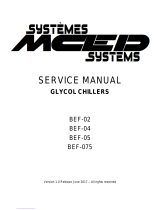
Signal specication of the process channel
Signal diagram for clockwise
rotation of the shaft looking
in direction "A"
1 period = 360° : 128
Access to the process data used for speed control, i.e., to the sine and cosine signals, is practically always "online". When the
supply voltage is applied, the speed controller has access to this information at any time. Sophisticated technology ensures stable
amplitudes of the analog signals across all specied environmental conditions, with a maximum variation of only 30 %.
Characteristics applicable to all stated ambient conditions
Signal Values/units
Signal peak, peak V
pp
of SIN, COS 0.8 … 1.1 V
Signal offset REFSIN, REFCOS 2.2 … 2.8 V
A
B
C
D
E
F
H
I
J
K
L
M
N
O
P
Q
R
S
T

SKS/SKM36 | SICK8010615/2015-11-18
Subject to change without notice
11
MOTOR FEEDBACK SYSTEM ROTARY HIPERFACE® SKS/SKM36
Type-specic settings SKS SKM
Type ID (command 52h) 32h 37h
Free E
2
PROM [bytes] 1,792 1,792
Address 40h 40h
Mode_485 E4h E4h
Codes 0 to 3 55h 55h
Counter 0 0
Overview of supported commands SKS SKM
Command byte Function Code 0
1)
Comment Comment
42h Read position 12 bits 24 bits
43h Set position
C
44h Read analog value Channel number 48 h Channel number 48 h
Temperature [°C] Temperature [°C]
46h Read counter
47h Increase counter
49h Delete counter
C
4Ah Read data
4Bh Store data
4Ch Determine status of a data eld
4Dh Create data eld
4Eh Determine available memory area
4Fh Change access code
50h Read encoder status
52h Read out type label Encoder type = 32h Encoder type = 37h
53h Encoder reset
55h Allocate encoder address
C
56h Read serial number and program version
57h Congure serial interface
C
6AH
Set position with synchronization to process
data channel
1)
The commands thus marked include the parameter "Code 0". Code 0 is a byte inserted into the protocol to provide additional protection of vital system parameters
against accidental overwriting. When the device is delivered, "Code 0" = 55h.
A
B
C
D
E
F
H
I
J
K
L
M
N
O
P
Q
R
S
T

Subject to change without notice
SKS/SKM36 | SICK12
SKS/SKM36 | SICK 8010615/2015-11-18
SKS/SKM36 MOTOR FEEDBACK SYSTEM ROTARY HIPERFACE®
Overview of status messages SKS SKM
Status code Description
Error type 00h The encoder has not detected any faults
C C
Initialization
01h Incorrect alignment data
C C
02h Incorrect internal angular offset
C C
03h Data eld partitioning table destroyed
C C
04h Analog limit values not available
C C
05h Internal I
2
C bus not operational
C C
06h Internal checksum error
C C
Protocol
07h Encoder reset occurred as a result of program monitoring
C C
09h Parity error
C C
0Ah Checksum of transmitted data is incorrect
C C
0Bh Unknown command code
C C
0Ch Number of transmitted data is incorrect
C C
0Dh Transmitted command argument is not allowed
C C
Data
0Eh The selected data eld must not be written to
C C
0Fh Incorrect access code
C C
10h Size of specied data eld cannot be changed
C C
11h Specied word address lies outside the data eld
C C
12h Access to non-existent data eld
C C
Position
01h Analog signals outside specication
1Fh Speed too high, no position formation possible
20h Singleturn position unreliable
C C
21h Multiturn position error
C
22h Multiturn position error
C
23h Multiturn position error
C
Other
1Ch Value monitoring of the analog signals (process data)
1Dh Transmitter current critical (contamination, transmitter breakage)
C C
1Eh Encoder temperature critical
C C
08h Counter overow
C C
For additional information about the interface see HIPERFACE
®
- description, part no. 8010701.
A
B
C
D
E
F
H
I
J
K
L
M
N
O
P
Q
R
S
T

SKS/SKM36 | SICK8010615/2015-11-18
Subject to change without notice
13
MOTOR FEEDBACK SYSTEM ROTARY HIPERFACE® SKS/SKM36
Accessories
Programming and conguration tools
Brief description Model name Part no.
Programming tool for HIPERFACE
®
motor feedback systems PGT-03-S 1034252
Mounting systems
Mounting brackets/plates
Figure Brief description Usable for Model name Part no.
Mounting bracket for encoder with 25 mm centering collar including
mounting kit for face mount ange
Stand-alone BEF-WF-25 2032621
Flanges
Mounting ange
Figure Brief description Usable for Model name Part no.
Flange adapter, adapts face mount ange with 25 mm centering collar
to size 60 face mount ange with 36 mm centering collar, aluminum
Stand-alone BEF-FA-025-036 2034226
Flange adapter, adapts face mount ange with 25 mm centering collar
to 50 mm servo ange, aluminum
Stand-alone BEF-FA-025-050 2032622
Flange adapter, adapts face mount ange with 25 mm centering collar
to 60 mm square mounting plate, aluminum
Stand-alone BEF-FA-025-060RCA 2032623
Flange adapter, adapts face mount ange with 25 mm centering collar
to 60 mm square mounting plate with shock absorber, aluminum
Stand-alone BEF-FA-025-060RSA 2032624
Flange adapter, adapts face mount ange with 25 mm centering collar
to 63 mm square mounting plate, aluminum
Stand-alone BEF-FA-025-063-REC 2033631
Other mounting accessories
Mounting tools
Brief description Usable for Model name Part no.
SKx36 mounting tool Built-in BEF-MW-SKX36 2031079
Servo clamps
Figure Brief description Usable for Model name Part no.
Servo clamps, small, for servo ange (clamps, eccentric fastener),
(3 pcs.), without fastening material
Stand-alone BEF-WK-RESOL 2039082
A
B
C
D
E
F
H
I
J
K
L
M
N
O
P
Q
R
S
T

Subject to change without notice
SKS/SKM36 | SICK14
SKS/SKM36 | SICK 8010615/2015-11-18
SKS/SKM36 MOTOR FEEDBACK SYSTEM ROTARY HIPERFACE®
Shaft adaptation
Shaft couplings
Figure Brief description Usable for Model name Part no.
Bellows coupling, shaft diameter 6 mm / 6 mm Stand-alone KUP-0606-B 5312981
Bellows coupling, shaft diameter 6 mm/10 mm Stand-alone KUP-0610-B 5312982
Plug connectors and cables
Connecting cable (female connector open)
Figure Brief description Usable for
Length of
cable Model name Part no.
Female connector JST, 8-pin, straight, for eld assembly,
unscreened
Built-in 0.2 m DOL-0J08-G0M2XB6 2031086
Female cable connector, 8-pin, straight, pre-wired with
8-wire cable, 4 x 2 x 0.25 mm², screened, cable diameter
7.0 mm
Stand-alone
2 m DOL-1208-G02MAC1 6032866
5 m DOL-1208-G05MAC1 6032867
10 m DOL-1208-G10MAC1 6032868
20 m DOL-1208-G20MAC1 6032869
Female connector (ready to assemble)
Figure Brief description Usable for Model name Part no.
M12 female cable connector, 8-pin, straight, screened, suitable for
cable diameter 4 - 8 mm
Stand-alone DOS-1208-GA01 6045001
Cable (open-open)
Brief description Usable for Model name Part no.
Cable, HIPERFACE
®
, suitable for drag chain, PUR halogen-free, screened Stand-alone LTG-2708-MW 6028361
Male connector (ready to assemble)
Figure Brief description Usable for Model name Part no.
M12 male cable connector, 8-pin, straight, screened, suitable for
assembly with cable diameter 4 - 8 mm
Stand-alone STE-1208-GA01 6044892
A
B
C
D
E
F
H
I
J
K
L
M
N
O
P
Q
R
S
T

SKS/SKM36 | SICK8010615/2015-11-18
Subject to change without notice
15
MOTOR FEEDBACK SYSTEM ROTARY HIPERFACE® SKS/SKM36
Dimensional drawings, accessories (dimensions in mm (inch) )
Mounting brackets/plates
BEF-WF-25
2 x 45°
120°
A
A-A
A
Ø 33.5
+0.1
(1.32)
3 x Ø 4.2
±0.1
(0.17)
Ø 25 H8
(0.98)
6
(0.24)
Ø 8
+0.1
(0.31)
72 (2.83)
45°
40 (1.57)
Ø 7
+0.1
(0.28)
35 (1.38)
60 (2.36)
22
(0.87)
45 (1.77)
Mounting ange
BEF-FA-025-036
General tolerances according to ISO 2768-mk
A
3 x 120°
3 x 120°
Ø 36 f8
(1.42)
A
3 x 8
(0.31)
Ø 33.5
±0.1
(1.32)
Ø 48
±0.1
(1.89)
A-A
0.05
A
5
(0.20)
Ø 58 (2.28)
3 x Ø 8
+0.1
(0.31)
3 x Ø 4.2
+0.1
(0.17)
Ø 25 H8
(0.98)
A
3 x M4
0.02
A
8.1
+0.1
(0.32)
A
B
C
D
E
F
H
I
J
K
L
M
N
O
P
Q
R
S
T

Subject to change without notice
SKS/SKM36 | SICK16
SKS/SKM36 | SICK 8010615/2015-11-18
SKS/SKM36 MOTOR FEEDBACK SYSTEM ROTARY HIPERFACE®
BEF-FA-025-050
General tolerances according to ISO 2768-mk
A
3 x 120°
3 x 120°
A
Ø 33.5
±0.1
(1.32)
Ø 42
±0.1
(1.65)
A-A
0.05
A
Ø 58 (2.28)
3 x Ø 8
+0.1
(0.31)
3 x Ø 4.2
+0.1
(0.17)
Ø 25 H8
(0.98)
A
0.02
A
3 x M4
Ø 50 f8 (1.97)
Ø 50 (1.97)
4–0.1
(0.16)
R
z
6.3
45°
8.1
+0.1
(0.32)
3
(0.12)
BEF-FA-025-060RCA
General tolerances according to ISO 2768-mk
58
±0.1
(2.28)
48
±0.1
(1.89)
A
A
4 x R4
Ø 33.5
±0.1
(1.32)
3 x Ø 4.2
+0.1
(0.17)
Ø 25 H8
(0.98)
A-A
Ø 4.5
(0.18)
Ø 8
+0.1
(0.31)
4
(0.16)
45°
3 x 120°
BEF-FA-025-060RSA
General tolerances according to ISO 2768-mk
10
(0.39)
4
(0.16)
10
(0.39)
4 x Ø 10
±0.3
(0.39)
58
±0.2
(2.28)
48
±0.1
(1.89)
A
B
C
D
E
F
H
I
J
K
L
M
N
O
P
Q
R
S
T

SKS/SKM36 | SICK8010615/2015-11-18
Subject to change without notice
17
MOTOR FEEDBACK SYSTEM ROTARY HIPERFACE® SKS/SKM36
BEF-FA-025-063-REC
General tolerances according to ISO 2768-mk
A
25°
4 x R4
63
±0.2
(2.48)
52.4
±0.2
(2.06)
3 x 120°
a
Ø 25 H8
(0.98)
Ø 33.5
±0.1
(1.32)
A
A-A
3 x Ø 4.2
+0.1
(0.17)
3 x Ø 8
+0.1
(0.31)
4 x Ø 5.5
(0.22)
4
(0.16)
45°
Mounting tools
BEF-MW-SKX36
General tolerances according to ISO 2768-mk
Servo clamps
BEF-WK-RESOL
Ø 10–0.2
(0.39)
4–0.1
(0.16)
2.3
–0.1
(0.09)
8.5
(0.33)
Ø 3.1
+0.
1
(0.12)
Ø 6
(0.24)
A
B
C
D
E
F
H
I
J
K
L
M
N
O
P
Q
R
S
T

Subject to change without notice
SKS/SKM36 | SICK18
8010615/2015-11-18
SKS/SKM36 MOTOR FEEDBACK SYSTEM ROTARY HIPERFACE®
SKS/SKM36 | SICK
Shaft couplings
KUP-0606-B
KUP-0610-B
Cheese-head screw
M2.5 x 8, DIN 912 A2
21
±1
(0.83)
29
±1
(1.14)
Ø d1
H8
Ø d2
H8
Connecting cable (female connector open)
DOL-0J08-G0M2XB6
220
+5
(8.66)
70 (2.76)
(0.)
20 (0.79)
X
shrunk area
DOL-1208-G02MAC1
DOL-1208-G05MAC1
DOL-1208-G10MAC1
DOL-1208-G20MAC1
All dimensions in mm (inch)
1/brn
2/wht
3/blk
4/pnk
5/yel
6/vio
7/blu
8/red
Female connector (ready to assemble)
DOS-1208-GA01
Male connector (ready to assemble)
STE-1208-GA01
A
B
C
D
E
F
H
I
J
K
L
M
N
O
P
Q
R
S
T

SKS/SKM36 | SICK8010615/2015-11-18
Subject to change without notice
19
SERVICES FOR MACHINES AND SYSTEMS: SICK LifeTime Services
Our comprehensive and versatile LifeTime Services are the perfect addition to the comprehensive range of products from
SICK. The services range from product-independent consulting to traditional product services.
Training and education
Practical, focused and professional
Upgrade and retrots
Easy, safe and economical
Consulting and design
Safe and professional
Verication and optimization
Safe and regularly inspected
Product and system support
Reliable, fast and on-site
SERVICES
REGISTER AT WWW.SICK.COM TODAY AND
ENJOY ALL THE BENEFITS
Select products, accessories, documentation and soft-
ware quickly and easily.
Create, save and share personalized wish lists.
View the net price and date of delivery for every product.
Requests for quotation, ordering and delivery tracking
made easy.
Overview of all quotations and orders.
Direct ordering: submit even very complex orders in
moments.
View the status of quotations and orders at any time.
Receive e-mail notifications of status changes.
Easily repeat previous orders.
Conveniently export quotations and orders to work with
your systems.
m
m
m
m
m
m
m
m
m

SICK AG | Waldkirch | Germany | www.sick.com
SICK AT A GLANCE
SICK is a leading manufacturer of intelligent sensors and sensor solutions for industrial applications. With
almost 7,000 employees and over 50 subsidiaries and equity investments as well as numerous representati-
ve ofces worldwide, we are always close to our customers. A unique range of products and services creates
the perfect basis for controlling processes securely and efciently, protecting individuals from accidents and
preventing damage to the environment.
We have extensive experience in various industries and understand their processes and requirements. With
intelligent sensors, we can deliver exactly what our customers need. In application centers in Europe, Asia
and North America, system solutions are tested and optimized in accordance with customer specications.
All this makes us a reliable supplier and development partner.
Comprehensive services round out our offering: SICK LifeTime Services provide support throughout the
machine life cycle and ensure safety and productivity.
For us, that is “Sensor Intelligence.”
Worldwide presence:
Australia, Austria, Belgium, Brazil, Canada, Chile, China, Czech Republic, Denmark, Finland, France,
Germany, Great Britain, Hungary, India, Israel, Italy, Japan, Malaysia, Mexico, Netherlands, New Zealand,
Norway, Poland, Romania, Russia, Singapore, Slovakia, Slovenia, South Africa, South Korea, Spain,
Sweden, Switzerland, Taiwan, Thailand, Turkey, United Arab Emirates, USA, Vietnam.
Detailed addresses and additional representatives
- www.sick.com
8010615/2015-11-18 ∙ 7M_JS ∙ Pre USmod en44
/