Intellisystem IT-7302-PC Owner's manual
- Category
- Network media converters
- Type
- Owner's manual
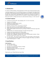
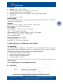
Intellisystem IT-7302-PC is a high-performance E1 fiber optic modem developed by using a dedicated integrated circuit to transmit one E1 channel in framing or non-framing mode with E1 time slot in arbitrary option. Balanced 120Ω/non-balanced 75Ω interfaces are automatic. Remote loop back function and pseudo-random code test function is supported, providing convenience for the test of optic fiber line status. With 120km trucking -free transmission distance for single-mode optic fiber, the device can be communicated with V.35 fiber modem.
Intellisystem IT-7302-PC is a high-performance E1 fiber optic modem developed by using a dedicated integrated circuit to transmit one E1 channel in framing or non-framing mode with E1 time slot in arbitrary option. Balanced 120Ω/non-balanced 75Ω interfaces are automatic. Remote loop back function and pseudo-random code test function is supported, providing convenience for the test of optic fiber line status. With 120km trucking -free transmission distance for single-mode optic fiber, the device can be communicated with V.35 fiber modem.


-
 1
1
-
 2
2
-
 3
3
-
 4
4
-
 5
5
-
 6
6
-
 7
7
-
 8
8
-
 9
9
-
 10
10
-
 11
11


Intellisystem IT-7302-PC Owner's manual
- Category
- Network media converters
- Type
- Owner's manual
Intellisystem IT-7302-PC is a high-performance E1 fiber optic modem developed by using a dedicated integrated circuit to transmit one E1 channel in framing or non-framing mode with E1 time slot in arbitrary option. Balanced 120Ω/non-balanced 75Ω interfaces are automatic. Remote loop back function and pseudo-random code test function is supported, providing convenience for the test of optic fiber line status. With 120km trucking -free transmission distance for single-mode optic fiber, the device can be communicated with V.35 fiber modem.
Ask a question and I''ll find the answer in the document
Finding information in a document is now easier with AI
Related papers
Other documents
-
CTC Union FRM220 User manual
-
 Turin Networks TE-50-EV User manual
-
-
Cabletron Systems CyberSWITCH CSX400 Installation guide
-
Alcatel-Lucent 7302 Information Manual
-
Patton electronic 2701RC User manual
-
Greenlee Datascout 10G User Manual User manual
-
Juniper PF-24XGE-SFPP Datasheet
-
-
