VADDIO RoboSHOT 30 HDBT Installation guide
- Category
- Camera accessories
- Type
- Installation guide
This manual is also suitable for

Installation Guide for
RoboSHOT 12 HDBT and
RoboSHOT 30 HDBT
High-Performance PTZ Cameras
Document 411-0003-31 Rev B
February 2017

ii
Contents
Overview 1
What's in this Guide 1
Camera Features 1
Unpacking the Camera 2
A Quick Look at the Camera 5
Front of the Camera 5
Back of the Camera 6
Switch Settings 6
Video Resolution 6
Camera Settings 7
Installation 8
Before You Install the Camera 8
Don’t Void Your Warranty! 8
Operation, Storage, and Care 8
Cabling Notes 9
Installing the Wall Mount 10
About Ceiling-Mounted Cameras 10
Basic Connection Diagram 11
Options for Power and Other Connections 11
Installing the Camera 12
Powering Up the Camera 13
Next Steps 13
Compliance Statements and Declarations of Conformity 14
FCC Part 15 Compliance 14
ICES-003 Compliance 14
European Compliance 15
Warranty Information 16
Index 17

1
Overview
This guide covers the RoboSHOT™ 12 and 30 HDBT PTZ cameras:
n RoboSHOT 12 HDBT (silver), North America – 999-9960-000
n RoboSHOT 12 HDBT (silver), Europe and UK – 999-9960-001
n RoboSHOT 12 HDBT (silver), Australia and New Zealand – 999-
9960-009
n RoboSHOT 30 HDBT (black), North America – 999-9963-000
n RoboSHOT 30 HDBT (black), Europe and UK – 999-9963-001
n RoboSHOT 30 HDBT (black), Australia and New Zealand – 999-9963-009
n RoboSHOT 30 HDBT (white), North America – 999-9963-000W
n RoboSHOT 30 HDBT (white), Europe and UK – 999-9963-001W
n RoboSHOT 30 HDBT (white), Australia and New Zealand – 999-9963-009W
What's in this Guide
This guide covers:
n Unpacking the camera
n Tips for a successful installation
n Instructions for installing the camera mount
n Information on connecting and mounting the camera
n Camera power-on
Complete product information is available in the Integrator's Complete Guide to RoboSHOT HDBT
High-Performance PTZ Cameras.
Download manuals, dimensional drawings, and other information from www.vaddio.com/support.
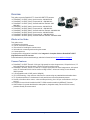
Camera Features
n RoboSHOT 12 HDBT: Exmor® 1/2.8 type, high-speed, low-noise image sensor; 12X optical zoom; 73°
horizontal field of view in wide mode – perfect for small to medium rooms
n RoboSHOT 30 HDBT: Exmor R™ back-lit 1/2.8 type, high-speed, low-noise image sensor; 30X optical
zoom; 65° horizontal field of view for medium to large venues – houses of worship, lecture theaters,
IMAG systems
n 2.38 megapixels total, full HD (native 1080p/60)
n IP H.264 streaming – view real-time video from the camera using any standards-based media viewer
n Tri-Synchronous Motion™ simultaneous 3-axis pan/tilt/zoom movement between presets
n Smooth, silent direct-drive motors – ultra-accurate positioning, from 120° per second down to 0.35° per
second
n Designed for use with the Vaddio OneLINK™ HDMI extension module for HDBaseT Cameras
n Web interface for remote administration and operation, integration-ready Telnet or RS-232 control,
presenter-friendly IR remote control

Unpacking the Camera
Make sure you received all the items you expected. Here are the packing lists for the RoboSHOT HDBT
cameras.
Caution
Always support the camera's base when picking it up. Lifting the camera by its head or mounting
arm will damage it.
RoboSHOT 12 HDBT, North America – 999-9960-000
n RoboSHOT 12 HDBTCamera (998-9960-000)
n Thin Profile Wall Mount with Mounting Hardware (535-2000-240)
n Vaddio IR Remote Commander (998-2100-000)
n 12 VDC, 3.0 Amp Switching Power Supply
n AC Cord Set for North America
n Quick-Start Guide (342-1219)
RoboSHOT 12 HDBT, Europe and UK – 999-9960-001
n RoboSHOT 12 HDBTCamera (998-9960-000)
n Thin Profile Wall Mount with Mounting Hardware (535-2000-240)
n Vaddio IR Remote Commander (998-2100-000)
n 12 VDC, 3.0 Amp Switching Power Supply
n Euro Power Cord
n UK Power Cord
n Quick-Start Guide (342-1219)
2
Installation Guide for RoboSHOT HDBT High-Performance PTZ Cameras

RoboSHOT 12 HDBT, Australia and New Zealand – 999-9960-009
n RoboSHOT 12 HDBTCamera (998-9960-000)
n Thin Profile Wall Mount with Mounting Hardware (535-2000-240)
n Vaddio IR Remote Commander (998-2100-000)
n 12 VDC, 3.0 Amp Switching Power Supply
n Power Cord for Australia and New Zealand
n Quick-Start Guide (342-1219)
RoboSHOT 30 HDBT, North America, black – 999-9963-000
RoboSHOT 30 HDBT, North America, white – 999-9963-000W
n RoboSHOT 30 HDBT Camera (998-9963-000 or 998-9963-000W)
n Thin Profile Wall Mount with Mounting Hardware, black or white depending on camera color (535-2000-
240 or 535-2000-240W)
n Vaddio IR Remote Commander (998-2100-000)
n 12 VDC, 3.0 Amp Switching Power Supply
n AC Cord Set for North America
n Quick-Start Guide (342-1219)
OR
3
Installation Guide for RoboSHOT HDBT High-Performance PTZ Cameras

RoboSHOT 30 HDBT, Europe and UK, black – 999-9963-001
RoboSHOT 30 HDBT, Europe and UK, white – 999-9963-001W
n RoboSHOT 30 HDBT Camera
n Thin Profile Wall Mount with Mounting Hardware, black or white depending on camera color (535-2000-
240 or 535-2000-240W)
n Vaddio IR Remote Commander (998-2100-000)
n 12 VDC, 3.0 Amp Switching Power Supply
n Euro Power Cord
n UK Power Cord
n Quick-Start Guide (342-1219)
OR
RoboSHOT 30 HDBT, Australia and New Zealand, black – 999-9963-009
RoboSHOT 30 HDBT, Australia and New Zealand, white – 999-9963-009W
n RoboSHOT 30 HDBT Camera
n Thin Profile Wall Mount with Mounting Hardware, black or white depending on camera color (535-2000-
240 or 535-2000-240W)
n Vaddio IR Remote Commander (998-2100-000)
n 12 VDC, 3.0 Amp Switching Power Supply
n Power Cord for Australia and New Zealand
n Quick-Start Guide (342-1219)
OR
Download manuals, dimensional drawings, and other information from www.vaddio.com/support.
4
Installation Guide for RoboSHOT HDBT High-Performance PTZ Cameras

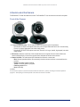
A Quick Look at the Camera
The RoboSHOT 12 and 30 models are similar. The RoboSHOT 12 is the camera on the left in the photo.
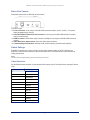
Front of the Camera
n Camera and Zoom Lens: The 12 and 30 models use different optical components.
o
RoboSHOT 12 HDBT:12X optical zoom lens (12X in Super-Wide mode and 10X in normal mode),
Exmor 1/2.8-type, high-speed, low noise image sensor
o
RoboSHOT 30 HDBT: 30X optical zoom lens, Exmor-R 1/2.8 type, backlit, high-speed, low-noise,
image sensor
n IR Sensors: Sensors in the front of the camera base receive signals from the remote. Make sure
there's nothing directly in front of the camera base, and point the remote at the camera.
n Status indicator: The multicolored LED indicates the camera's current state.
o
Blue: Normal operation (blinks off momentarily when the camera receives a command from the
remote)
o
Purple: In standby mode or booting
o
Yellow: Firmware update in progress
o
Flashing purple: Error
o
Red: On-air tally
Caution
Do not remove power or reset the camera while the indicator is yellow, showing a firmware update in
progress. Interrupting a firmware update can make the camera unusable.
5
Installation Guide for RoboSHOT HDBT High-Performance PTZ Cameras

Back of the Camera
Rear panel connections are identical for both models.
From left to right:
n Power connector: If not using a OneLINK HDMI extension module, use the 12 VDC, 3.0 A power
supply shipped with the camera.
n OneLINK HDBaseT/Network RJ-45 connector: If not using a OneLINK HDMI extension module,
connect to the network.
n HDMI connector: HDMI video output; connect to a display if not using a OneLINK HDMI extension
module.
n Video Resolution Select switch: Select the video output resolution.
n Camera Settings DIP switches: Settings for IR remote frequency, baud rate and image flip.
Switch Settings
RoboSHOT cameras use a rotary switch to set the video resolution and a set of DIP switches that
determine certain camera functions. A label on the bottom of the camera provides a quick reference for
setting the switches.
Note
Set the switches appropriately before mounting the camera.
Video Resolution
Set the desired output resolution for the camera with the rotary switch. Switch positions 9 through D are not
used.
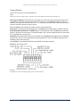
Switch position Resolution
0 720p/59.94
1 1080i/59.94
2 1080p/59.94
3 720p/60
4 1080i/60
5 1080p/60
6 720p/50
7 1080i/50
8 1080p/50
9 – D Not used
E 1080p/30
F 1080p/25
6
Installation Guide for RoboSHOT HDBT High-Performance PTZ Cameras

Camera Settings
Use the DIP switches to set camera behaviors.
Note
When the camera is right side up, switches are in their default positions when they are up.
IR Frequency Selection:The IR Remote Commander can control up to three cameras in the same room
independently, if they are configured with different IR frequencies. Use switches 1 and 2 to select the
frequency to identify the camera as camera 1, 2, or 3; then use the Camera Select buttons at the top of the
remote to select the camera you want to control.
IR: Leave switch 3 in the default UP position if the IR remote will be used.
Image Flip: If mounting the camera upside-down, set switch 4 to the DOWN position: IMAGE FLIP ON.
Super Wide Mode (RoboSHOT 12 HDBT only): To use Super-wide mode, set switch 5 to the DOWN
position. This gives 12X zoom with a 73º horizontal angle of view. Normal mode provides 10X zoom with a
67.2º horizontal field of view (HFOV).
Baud Rate:Set the baud rate for RS-232 communication using switch 6. Most applications use 9600 bps
(switch 6 UP), which is recommended when using long cable runs. Use the 38,400 bps setting (switch 6
DOWN) for short control lines only.
Leave Switch 7 in the default UP position unless sRGB color output is needed.
Switch 8 is not currently used.
Pro Tip
Double-check switch settings before you mount the camera.
7
Installation Guide for RoboSHOT HDBT High-Performance PTZ Cameras

Installation
This section covers
n Siting the camera
n Installing the mount
n Connecting the camera
n Installing the camera
Before You Install the Camera
n Choose a camera mounting location that will optimize camera performance. Consider camera viewing
angles, lighting conditions, line-of-sight obstructions, and in-wall obstructions where the camera is to be
mounted.
n If the IR Remote Commander will be used, ensure that nothing blocks the IRlens in the camera's base.
n Ensure that the camera body can move freely and point away from the ceiling and lights.
n Follow the installation instructions included with the camera mount.
Don’t Void Your Warranty!
Caution
This product is for indoor use. Do not install it outdoors or in a humid environment without the appropriate
protective enclosure. Do not allow it to come into contact with any liquid.
Use only the power supply included with this product. Using a different one will void the warranty, and
could create unsafe operating conditions or damage the product.
Do not install or operate this product if it has been dropped, damaged, or exposed to liquids. If any of these
things happen, return it to Vaddio for safety and functional testing.
DomeVIEW enclosures are available to allow outdoor installation of RoboSHOT cameras. Learn more at
www.vaddio.com/products.
Operation, Storage, and Care
For smears or smudges on the product, wipe with a clean, soft cloth. Use a lens cleaner on the lens. Do not
use any abrasive chemicals.
Keep this device away from food and liquids.
Do not operate or store the device under any of the following conditions:
n Temperatures above 40°C (104°F) or below 0°C (32°F)
n High humidity, condensing or wet environments
n Inclement weather
n Severe vibration
n Between converging tectonic plates
n Dry environments with an excess of static discharge
Do not attempt to take this product apart. There are no user-serviceable components inside.
8
Installation Guide for RoboSHOT HDBT High-Performance PTZ Cameras

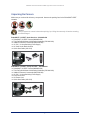
Cabling Notes
Use Cat-5e or better cable and standard RJ-45 connectors (568B termination). We recommend using high-
quality connectors and a high-quality crimping tool.
Caution
Check Cat-5 cables for continuity before using them. Using the wrong pin-out may damage the camera
system and void the warranty.
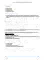
Note
Use standard RJ-45 connectors and a good crimping tool. Do not use pass-through
RJ-45 connectors. Poorly crimped connectors can damage the connectors on the
product, cause intermittent connections, and degrade signal quality. Test cable pin-
outs and continuity before connecting them.
Intact – Contact fingers will make reliable
contact with the cable connector
Damaged – Some contact fingers are bent
and will NOT make reliable contact with the
cable connector
Pro Tip
To prevent tragic mishaps, label both ends of every cable.
9
Installation Guide for RoboSHOT HDBT High-Performance PTZ Cameras

Installing the Wall Mount
All RoboSHOT cameras include a Thin Profile Wall Mount. Other mounting options are available as well.
Contact us if you don't have the camera mount you need.
You can install the camera wall mount to a 2-gang wall box or directly to the drywall.
n If you mount it to drywall, use the wall anchors provided with the wall mount.
n If you mount it to a wall box, use the cover plate screws supplied with the wall box.
About Ceiling-Mounted Cameras
If you use an inverted mount, set the camera's Image Flip DIP switch ON for inverted operation.
See Camera Settings for more information.
10
Installation Guide for RoboSHOT HDBT High-Performance PTZ Cameras

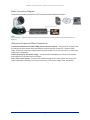
Basic Connection Diagram
The Quick-Start Guide for RoboSHOT HDBT Cameras provides additional information.
Note
The OneLINK™ HDMI extension module is not required; the camera can be connected directly to the
network.
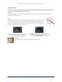
Options for Power and Other Connections
Connect the camera to a OneLINK HDMI camera extension module – a single Cat-5e (or better) cable
provides power to the camera, along with HDBaseT network and video connectivity. Network, HDMI
output, and RS-232 control are connected at the OneLINK module. Do not use the camera's 12 VDC power
supply in this configuration.
Use the provided 12 VDC power supply – use the camera's OneLINK port to connect to the network,
and connect the HDMI video output to a display.
Use a PoE+ power injector – Connect to the network through a PoE+ power injector, and connect the
HDMI video output to a display. Do not use the camera's 12 VDC power supply in this configuration.
11
Installation Guide for RoboSHOT HDBT High-Performance PTZ Cameras

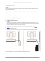
Installing the Camera
Caution
Before you start, be sure you can identify all cables correctly. Connecting a cable to the wrong port can
result in equipment damage.
Caution
Check Cat-5 cables for continuity before using them. Using the wrong pin-out may damage the camera
system and void the warranty.
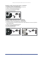
1. Route the cables to the camera location.
2. Route the cables through the mount, and install the mount on the wall or attach it to the wall box. Leave
the screws loose enough to adjust the position of the mount.
3. Level the mount and tighten the mounting screws.
4. Check the level again.
5. Connect the cables to the camera.
Caution
If using local power rather than connecting to a OneLINK extension module or using PoE+, use the
power supply shipped with the camera. Using a different power supply may create an unsafe operating
condition or damage the camera, and will void the warranty.
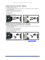
6. Ensure that the video resolution switch and the DIP switches are set appropriately. See Switch
Settings.
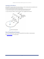
7. Place the camera on the mount.
8. Attach the camera to the mount using the ¼”-20 x .375 mounting screw supplied with the camera.
Image for illustration only; not to scale. Camera and mount details may differ.
12
Installation Guide for RoboSHOT HDBT High-Performance PTZ Cameras

Powering Up the Camera
Connect camera power.
The camera will wake up and initialize. This will take a few seconds.When the camera is initialized and
ready, its front indicator is blue. At this point, it is ready to accept control information.
Note
Wait until the camera finishes initializing before trying to control it using the IRremote or other command
input.
Next Steps
The camera is now ready to configure and use. This information is available in the Configuration and
Administration Guide for RoboSHOT HDBT High-Performance PTZ Cameras. It is also included in
the Integrator's Complete Guide to RoboSHOT HDBT High-Performance PTZ Cameras.
13
Installation Guide for RoboSHOT HDBT High-Performance PTZ Cameras

Compliance Statements and Declarations of Conformity
Compliance testing was performed to the following regulations:
FCC Part 15 (15.107, 15.109), Subpart B Class A
ICES-003, Issue 54: 2012 Class A
EMC Directive 2004/108/EC Class A
EN 55022: December 2010 Class A
EN 55024: November 2010 Class A
KN22 2008 (CISPR 22: 2006) Class A
KN24 2008 (CISPR 24: 1997 + A1: 2000 + A2: 2002) Class A
IEC 60950-1:2005 (2nd Edition); Am 1: 2009 + Am 2: 2013 Safety
EN 60950-1: 2006 + A11: 2009 + A1: 2010 + A12: 2011 + A2: 2013 Safety
FCC Part 15 Compliance
This equipment has been tested and found to comply with the limits for a Class A digital device, pursuant to
Part 15, Subpart B, of the FCC Rules. These limits are designed to provide reasonable protection against
harmful interference when the equipment is operated in a commercial environment. This equipment
generates, uses, and can radiate radio frequency energy and, if not installed and used in accordance with
the instruction manual, may cause harmful interference to radio communications. Operation of this
equipment in a residential area is likely to cause harmful interference in which case the user will be required
to correct the interference at his/her own expense.
Operation is subject to the following two conditions: (1) This device may not cause
interference, and (2) This device must accept any interference including interference that
may cause undesired operation of the device.
Changes or modifications not expressly approved by Vaddio can affect emission
compliance and could void the user’s authority to operate this equipment.
ICES-003 Compliance
This digital apparatus does not exceed the Class A limits for radio noise emissions from digital apparatus
set out in the Radio Interference Regulations of the Canadian Department of Communications.
Le présent appareil numérique n’emet pas de bruits radioélectriques
dépassant les limites applicables aux appareils numeriques de la classe A
préscrites dans le Règlement sur le brouillage radioélectrique édicte par le ministère des Communications
du Canada.
14
Installation Guide for RoboSHOT HDBT High-Performance PTZ Cameras

European Compliance
This product has been evaluated for electromagnetic compatibility under the EMC Directive for Emissions
and Immunity and meets the requirements for a Class A digital device. In a domestic environment this
product may cause radio interference in which case the user may be required to take adequate measures.
Standard(s) To Which Conformity Is Declared:
EMC Directive 2004/108/EC
EN 55022: December 2010 Conducted and Radiated Emissions
EN 55024: November 2010 Immunity
EN 61000-4-2: 1995 + Amendments A1: 1998 + A2: 2001 Electrostatic Discharge
EN 61000-4-3: 2006 + A1: 2008 Radiated Immunity
EN 61000-4-4: 2004 + Corrigendum 2006 Electrical Fast Transients
EN 61000-4-5: 2006 Surge Immunity
EN 61000-4-6: 2009 Conducted Immunity
EN 61000-4-8: 2010 Power Frequency Magnetic Field
EN 61000-4-11: 2004
Voltage Dips, Interrupts and
Fluctuations
KN22 2008 (CISPR 22: 2006) Conducted and Radiated Emissions
KN24 2008 (CISPR 24: 1997 + A1: 2000 + A2: 2002) IT Immunity Characteristics
EN 61000-4-2 Electrostatic Discharge
EN 61000-4-3 Radiated Immunity
EN 61000-4-4 Electrical Fast Transients
EN 61000-4-5 Surge Immunity
EN 61000-4-6 Conducted Immunity
EN 61000-4-8 Power Frequency Magnetic Field
EN 61000-4-11
Voltage Dips, Interrupts and
Fluctuations
IEC 60950-1: 2005 (2nd Edition); Am 1: 2009 + Am 2: 2013 Safety
EN 60950-1: 2006 + A11: 2009 + A1: 2010 + A12: 2011 + A2:
2013
Safety
15
Installation Guide for RoboSHOT HDBT High-Performance PTZ Cameras

Warranty Information
See Vaddio Warranty, Service and Return Policies posted on support.vaddio.com for complete details.
Hardware* warranty: Two (2) year limited warranty on all parts and labor for Vaddio manufactured
products.Vaddio warrants its manufactured products against defects in materials and workmanship for a
period of two years from the day of purchase, to the original purchaser, if Vaddio receives notice of such
defects during the warranty.Vaddio, at its option, will repair or replace products that prove to be
defective.Vaddio manufactures its hardware products from parts and components that are new or
equivalent to new in accordance with industry standard practices.
Exclusions:The above warranty shall not apply to defects resulting from improper or inadequate
maintenance by the customer, customers applied software or interfacing, unauthorized modifications or
misuse, mishandling, operation outside the normal environmental specifications for the product, use of the
incorrect power supply, modified power supply or improper site operation and maintenance.OEM and
special order products manufactured by other companies are excluded and are covered by the
manufacturer’s warranty.
Vaddio Customer Service:Vaddio will test, repair, or replace the product or products without charge if the
unit is under warranty. If the product is out of warranty, Vaddio will test then repair the product or
products.The cost of parts and labor charge will be estimated by a technician and confirmed by the
customer prior to repair.All components must be returned for testing as a complete unit.Vaddio will not
accept responsibility for shipment after it has left the premises.
Vaddio Technical Support:Vaddio technicians will determine and discuss with the customer the criteria
for repair costs and/or replacement. Vaddio Technical Support can be contacted by email at
support@vaddio.com or by phone at one of the phone numbers listed on support.vaddio.com.
Return Material Authorization (RMA) number:Before returning a product for repair or replacement
request an RMA from Vaddio’s technical support.Provide the technician with a return phone number, e-
mail address, shipping address, product serial numbers and original purchase order number.Describe the
reason for repairs or returns as well as the date of purchase. See the General RMA Terms and Procedures
section for more information. RMAs are valid for 30 days and will be issued to Vaddio dealers only.End
users must return products through Vaddio dealers. Include the assigned RMA number in all
correspondence with Vaddio.Write the assigned RMA number clearly on the shipping label of the box when
returning the product.All products returned for credit are subject to a restocking charge without
exception.Special order product are not returnable.
Voided varranty:The warranty does not apply if the original serial number has been removed or if the
product has been disassembled or damaged through misuse, accident, modifications, use of incorrect
power supply, use of a modified power supply or unauthorized repair.
Shipping and handling:Vaddio will not pay for inbound shipping transportation or insurance charges or
accept any responsibility for laws and ordinances from inbound transit.Vaddio will pay for outbound
shipping, transportation, and insurance charges for all items under warranty but will not assume
responsibility for loss and/or damage by the outbound freight carrier.If the return shipment appears
damaged, retain the original boxes and packing material for inspection by the carrier.Contact your carrier
immediately.
Products not under warranty: Payment arrangements are required before outbound shipment for all out of
warranty products.
16
Installation Guide for RoboSHOT HDBT High-Performance PTZ Cameras

Index
A
anatomy of the camera 5
B
baud rate setting 7
behavior on power-up 13
C
cable connectors 9
camera ID setting (DIP switch) 7
camera mount, installing 10
camera power 11
camera select See alsocamera ID setting
(DIP switch)
ceiling-mounted cameras 10
cleaning 8
color space setting 7
colors of the status light 5
connection example 11
connector identification 6
D
damage, preventing 8-9
DIP switch settings 7
I
image flip setting (DIP switch) 7
installation, typical 11
inverted installation 10
IR on/off (DIP switch) 7
L
locations of connectors 6
M
mounting cameras 8, 10, 12
O
OneLINK 11
OneLINK system 11
operating environment 8
P
packing lists 2
PoE+ power 11
power on/power off 13
power options 11
product returns and repairs 16
R
resolution 6
switch setting 6
RJ-45 connectors 9
S
shelf-mounted cameras 12
shelf, camera mount 10
status light, meanings of colors 5
storage environment 8
super-wide mode setting (DIP switch) 7
switch settings 7, 10
baud rate (DIP switch) 7
camera ID (DIP switch) 7
color space (DIP switch) 7
image flip (DIP switch) 7, 10
IR 7
super wide mode (DIP switch) 7
switch, video resolution 6
T
temperature, operating and storage 8
typical installation 12
V
video resolution setting 6
W
wall-mounted cameras 12
wall mount 10
warranty 8, 16
17

Vaddio is a brand of Milestone AV Technologies · www.vaddio.com · Phone 800.572.2011 /
+1.763.971.4400 · Fax +1.763.971.4464 · Email info@vaddio.com
Visit us at support.vaddio.com for firmware updates, specifications, drawings, manuals, technical support
information, and more. Vaddio, RoboSHOT, and OneLINKare trademarks or registered trademarks of
Milestone AV Technologies. HDBaseT™ and the HDBaseT Alliance logo are trademarks of the HDBaseT
Alliance. Exmor® is a trademark of Sony Corporation. All other brand names or marks are used for
identification purposes and are trademarks of their respective owners. In British Columbia, Milestone AV
Technologies ULC carries on business as MAVT Milestone AV Technologies ULC.
©2017 Milestone AV Technologies
-
 1
1
-
 2
2
-
 3
3
-
 4
4
-
 5
5
-
 6
6
-
 7
7
-
 8
8
-
 9
9
-
 10
10
-
 11
11
-
 12
12
-
 13
13
-
 14
14
-
 15
15
-
 16
16
-
 17
17
-
 18
18
-
 19
19
-
 20
20


VADDIO RoboSHOT 30 HDBT Installation guide
- Category
- Camera accessories
- Type
- Installation guide
- This manual is also suitable for
Ask a question and I''ll find the answer in the document
Finding information in a document is now easier with AI
Related papers
-
VADDIO RoboSHOT 30 HDBT Installation guide
-
VADDIO 999-9963-200 User guide
-
-
-
VADDIO OneLINK Bridge Installation guide
-
-
-
-
-
Other documents
-
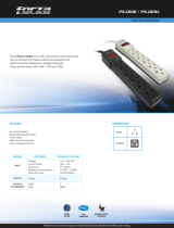 Forza Power Technologies PS-001B Datasheet
-
Kramer EXT3-POE-XR-R User guide
-
Logitech 915-000158 Datasheet
-
Camco P.9 Series User manual
-
3M Medical Release Liner 9968, 63# Paper, Configurable User guide
-
Milestone MacroPATH Series User manual
-
Apantac OG-HDBT-Rx User manual
-
Nokia ISAM ONT G-240W-C Owner's manual
-
Honeywell 9000A510STYLUS Datasheet
