Page is loading ...

P/ N 9 5 - 0 44 4
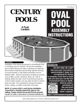
Above Ground Pool Assembly & Installation
Buttress Free and Traditional Buttress
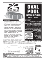
WA R N I N G :
THIS POOL IS NOT DESIGNED FOR DIVING OR
JUMPING.
DANGEROUS INJURY CAN RESULT-SHALLOW
WATER!!!
Follow All Safety and Maintenance Instructions
Your pool is designed for years of pleasurable, safe family fun. But, when
used incorrectly, a swimming pool can be dangerous. To insure your pool is
used safely you !"#$%observe the following safety precautions:
Do not dive!-Do not jump!- No rough play!- No running or pushing!
Do not walk on the top rail. It can be slippery and is not a walkway.
Be sure to install all safety labels provided with your pool according to the
instructions.
Keep a safety rope 1/4” by 50’ with a flotation buoy with an outside diameter oft
15”. Have accessible in a prominent area by your pool.
Post near all entrances to pool area; a list of telephone numbers of the:
• Nearest available police• Nearest ambulance service
• Nearest available fire department• Nearest available hospital
• Nearest available rescue unit• Nearest available physician
• 911 emergency number if available
Provide fencing or enclosure which is independent of the house as a closure
around the entire pool area. The fencing must be made of durable material, a
minimum of 4’ in height from ground level and with closures with self-latching
locks, to make pool inaccessible to toddlers and uninvited guests. Make sure
gate is always closed. Be sure to follow local building code requirements for load
capacity and fencing if using an aftermarket or homebuilt deck. You must make
sure all fence and barriers are in working order so that pool is always protected.
Check with your local town for any special laws in your locale.
Never drink alcoholic beverages or use any intoxicants which could hinder your
judgment and reflexes.
Never use pool alone. All children must be supervised continuously.
Do not use pool if bottom is not clearly visible: At night, sufficient lighting must
be available. It is the pool owners sole responsibility to provide adequate
lighting for pool bottom, safety signs and walkways, which exceeds minimum
standards of the IES of North America.
Do not climb, stand or sit on any pool structure or the filter system. Components
such as the filtration system, pumps and heater must be positioned so as to
prevent their being used as a means of access to the pool by young children.
Be sure that all toys, chairs and tables or similar objects that a young child could
climb on be at least four feet (4’) from pool.
Do not use pool during electrical or rain storms.
See available National Spa and Pool Institute (NSPI), publications for more tips on pool safety.
IMPORTANT NOTICE!
READ BEFORE INSTALLATION
WA R N I N G :
DO NOT AFFIX
ANY OTHER PRODUCTS
MADE BY OTHERS
TO YOUR POOL
SUCH AS,
BUT NOT LIMITED TO ,
DECKS AND SLIDES !
ENCLOSED IN FRAME CARTON IS SAFETY
ENVELOPE. THE SAFETY STICKERS MUST
BE INSTALLED AS PER FOLLOWING
INSTRUCTIONS. FAILURE TO PROPERLY
INSTALL WARNING LABELS WILL VOID
WARRANTY. FAILURE TO MOUNT THESE
SAFETY LABELS MAY SUBJECT YOU TO
SUBSTANTIAL LIABILITY IN CASE OF INJURY.
SIGN MUST BE PLACED
ON WALL NEXT T ENTRYO
TO POOL
THESE WARNINGS ARE NOT TO
BE REMOVED UNDER ANY CIR-
CUMSTANCES! IF THEY BECOME
DISCOLORED OR FALL OFF,
PLEASE REQUEST REPLACE-
MENTS WHICH WILL BE SENTAT
NO CHARGE.
SIGN TO BE PLACED ON
LINER ABOVE WATER LINE
OPPOSITE ENTRY TO POOL

&'()*+ ,- (&* ' .
Congratulations on becoming the owner of a new above ground swimming pool. This is the instruction packet
for installing your swimming pool. The following are some helpful hints that you should take into consideration
before installing your pool.
1) Read through the entire instruction booklet before you begin. This will enable you to find out exactly what is
involved with installing your swimming pool before you begin. While you are going through the instructions,
please be aware that all of the diagrams are representative of a 15' x 30'/18' x 33' pool. If you have a different
size pool you will find that your pool has a different number of uprights than the ones in the diagrams.
2) DO NOT ATTEMPT INSTALLATION IN WINDY OR GUSTY WEATHER This will not only make.
installation more difficult, it may result in damage to your pool before it is completely installed.
3) Although we have broken down the installation into many simple steps, you will probably find that Steps 1
and 2 will be the most labor intensive and time consuming steps. Once you have completed those two steps
you should find that the rest of the installation moves along much more quickly.
4) Please be sure to review all safety material and local codes before beginning your installation. There is a yellow
safety envelope packed with your pool. This envelope contains safety material and warning stickers to be
placed on your pool. If you are missing any of these items please contact your dealer or the factory to obtain it.
The warranty is void if all safety precautions are not followed.
5) In the event that you need to make a warranty claim, it is important to know the size and model of your
swimming pool in order to expedite the handling of your claim. Please fill in the information below and keep
for your records. All of this information can be found on the labels attached to the cartons your pool is packed in.
NAME OF POOL:
SIZE OF POOL:
DATE OF PURCHASE:
NAME OF POOLWALL:
NAME OF LINER:
6) Make sure you have the necessary tools and materials before beginning your installation.
Below is a list of the tools and materials needed.
- Shovel
- Tape measure
- Phillips head screwdriver
- Duct tape
- Sand
- Filter
- Skimmer/Return fitting
- Carpenters level and/or transit (Optional)
- Patio Blocks (2" x 8" x 16")
- Box cutter (Razor blade)
- Tamp
- 5/16” wrench
- 1/4" wrench

/**0%0*-1(&*'.
Do not locate pool over underground lines,
septic tanks, under electrical lines, near hazardous
structures, or out of local code restrictions. It is
essential that the area selected for your pool has
a level and firm base. Do not assemble your pool
on asphalt, tar or oil base surfaces. Avoid areas
with sharp objects, or ground treated with weed
killer or other chemicals. Also avoid areas where
nut grass, Bermuda grass or bamboo grass grows,
as they can grow through your liner. Grass must
be removed. Do not place components such as
filters, pumps, and heaters in a way that they can
be used as a means of access to pool by young
children. Be sure to follow all local building codes
and obtain all building permits required for your area.
2345%6
7(8/%6%9%/)8/1)&':%(;8%7&(8.
Refer to the "True Size" diagram on the second page to see the dimensions of your swimming pool. Once you
have these measurements and have chosen a site to install your pool, mark or outline the ground where the pool
will be going using spray paint or some other marking agent. Please keep in mind that you will need some extra
room to work. Be sure to account for the space that the side supports extend out on each side of an oval pool.
The strap end channel extends out 37" from the wall of the pool on each of the two straight sides of a Traditional
Buttress Oval. If you have a Buttress-Free Oval Pool, the strap end channel extends only 19" out from the
wall on each side. Refer to the "Actual Size" chart for further clarification.
For example, a 15x30 oval should have the following space in order to install the pool.
(<=>3$3?@=A%B"$$<C##%*D=A.
32'
*BE SURE TO AVOID:
-All electrical wires
-All gas lines
-Septic tanks
-Cesspools
-Dry wells
-Tree roots/ stumps
-buried debris(trees,
building material, etc.)
-sudden slopes within 6’
of pool area
E
B"$$<C##F2<CC%*D=A.%G=<>!?<C
32'
23'4"
30'
15'2"
20'4"
30'
15'2"
2345%H
15 x 30
2345%H1
15 x 30
E*@IC%J?"%K=DC%$KC%=LL<?L<3=$C%=<C=%!=<MC>%?"$N%<C!?DC%=@J%#?>%$K=$%3#%3@% $K C% =<C=5%1A#?%OC%#"<C%$? %=D?3>%=AA%CACI$<3I=A%P3<C#N
%4=#%A3@C#N%#CL$3I%$=@M#N%IC##L??A#N%><J%PCAA#N%$<CC%<??$#N%#$"!L#N%O"<3C>%>CO<3#N%=@>%#">>C@%#A?LC#%P3$K3@%QR%?S%$KC%L??A%=<C=5
EE%1AA%S??$%L<3@$#%=<C%#K?P3@4%3AA"#$< =$ 3?@ %?S%$KC%G1)+T*)8%#$JAC5%/AC=#C%<C!C!OC<%$?%=>>%=LL<?U5%HVW%?@%C=IK%#3>C5
'*(8.%BCS?<C%J?"%L<CL=<C%$KC%#3$C%S3@>%J?"<%#3XC%L??A%S??$L<3@$%=$%$KC%C@>%?S%$KC#C%3@#$<"I$3?@#5%/AC=#C%L=J
I=<CS"A%=$$C@$3?@%$?%=AA%>3!C@#3?@#%?@%$KC%S??$L <3@ $%#? %$K= $%J?"%K=DC%C@?"4K%<??!%$?%3@#$=AA%J?"<%L??A5

7(8/%H%9%08Y80&':.
Once you have designated the space for installation, and have cleared away the sod in that area, you can begin
to level the ground. The ideal tool for doing this is a transit. If you do not have access to a transit, use a long
board (be sure that the board is perfectly straight) and a carpenters level, as shown in the diagram.
The key to properly leveling the surface for an above ground swimming pool is to start at the lowest point and
dig everything else down to that level. You do not want to build up the lower areas to be level with the higher
areas. Doing this will cause the ground to settle once the pool is full of water. If the ground settles it could
destroy your pool, which could be dangerous and is not covered under the warranty.
You will probably not be able to get the ground completely level until you lay out the frame, but the closer you
get it now the easier the job will be later. We recommend that you do not proceed until the entire site is within an
inch of being perfectly level.
Remove soil and grass to this level.
Remove grass only from low areas.
* DO NOT ADD DIRT TO LOW AREAS
2345%Z
2345%[

7(8/Z%9%,'/1-\&':%(;8%/**0.
Hardware Change Notice
The hardware supplied with your pool has been modified for an easier installation. The #12 screw supplied with your pool has
been changed from a “sheet metal screw” to a “self-drilling screw”.As shown in the pictures.
The self-drilling screw will make attaching the parts to the channel much easier (Fig.5 # 5)
The self-drilling screw does not have a point like a traditional sheet metal screw
In the diagrams below the self-drilling screw is item #9 and is used in two locations:
-
-
To attach #1 to #5
To attach #6 to #5
Self- drilling screw
image
Below are some generic diagrams of oval pool components to help you identify the parts and where they will be
used. &T/*)( 1' ( .%+?%@?$%=$$C!L$%$?%=##C!OAC%$KC#C%L=<$#%@?P5%*@IC%J?"%I?@S3<!%$K=$%J?"%K=DC%=AA%?S
$KC%I?!L?@C@ $#%@CC>C>%S?< %J?"<L??AN%I?@$3@"C%?@%P3$K%$KC%3@#$<"I$3?@# 5
()1+&(&*'10%B,(()877%*Y10%1778TB0GB,(()877F2)88%*Y10%1778TB0G.
2345%]
2345%Q
X 52 3/8" LONG
-Self Drilling
5"
- Self Drilling
CHANNEL 45 9/16"
5"

7(8/%[%F%/)8F1778TB0&':%(;8%7()1&:;(%7&+87%*2%1%()1+&(&*'10%B,(()877%*Y10%/**0%*'0G.
*** THESE INSTRUCTIONS ARE FOR TRADITIONAL BUTTRESS OVAL POOLS ONLY! IF
YOU HAVE A
A) Start by laying the strap end channels out on the ground so
that the open ends face down. Notice the two slots on top of
each of these channels. You will not be using these slots in
the construction of the pool, but pay attention to where they
are located in the diagrams. They indicate which way the
channels are facing. See Fig.7
B) Now take the straight side 4"x4" Upright and push it down
over the strap end channel where those slots are located.
Position the open end of the straight side upright to face the
short end of the channel (the inside of the pool) as shown
in Fig.8. The two holes on each side of the upright should
line up with two of the holes on each side of the strap end
channel. Secure the parts with two 5/16" x 5" bolts and
two 5/16" nuts. Repeat for all assemblies.
2345%^
C) Once all of the straight side uprights are attached, you can
begin attaching the struts. This is done by pushing the
angled end of the strut (the end with two holes on each
side) over the end of the strap end channel and the other
side around the straight side upright. The hole on each side
of the strut lines up with the hole in the straight side
upright that is farthest from the open end of the straight
side upright. The two holes on the other end of the strut
line up with the only two holes in the back end of the strap
end channel. Secure the struts using three 5/16" x 5"
bolts and three 5/16" nuts. See Fig.9 for visual instructions.
D) Now you can install the straight side bottom rail connectors.
Use one per strap end channel. Place the connector on top
of the strap end channel so that the open part of the
connector sits inside the straight side upright. The
hole in the straight side connector will line up
with the hole between the two slotson the strap
screw.end channel. Secure the piece using a
#12 x ¾"
See Fig.10 for visual instructions.
2345%6V
Slots
2345%_
2345%`
PA RT I D E N T I F I E R
self drilling
5"
*Please do not be alarmed if you are not using all of the holes in the strap end channels. We use this same
channel for a few different products so there are some holes that you will not be using for this pool.
/AC=#C%S?AA?P%>3=4<=!#%$?%OC%#"<C%J?"%=<C%"#3@4%=AA%?S%$KC%I?<<CI$%K?AC#5

10(8)'1(8%7(8/%[%F
/)8F1778TB0&':%(;8%7()1&:;(%7&+8 7%*2%1%B,(()877F2)88%*Y10%/**0%*'0G.
*** IF YOU HAVE A TRADITIONAL BUTTRESS OVAL, PLEASE REFER TO THE
1a%7$=<$%OJ%A=J3@4%?"$%$KC%"@>C<%O?U%IK= @@CA#%#? %$K= $%$K C% ?L C@
%%%#3>C#%?S%C=IK%"@>C<%O?U%IK=@@CA%3#%S=I3@4%"L5%(KC@%#A3>C%$KC
%%%#$<=L%C@>%IK=@@CA%?DC<%$K C%$?L%?S%$KC%"@>C<%O?U%IK=@@CA#%#?
%%%$K=$%$KCJ%S? <!%=%$"OC 5%BC%#"<C%$K=$%$KC%K?AC#%3@%O?$K%IK=@@ CA#
%%%=<C%=A34@C>N%O"$%>?%@?$%O?A$%$KC!%$?4C$KC<%JC$5%7CC%2345%66
52#3/8"
45#9/16"
2345%66
Ba%'?P%#A3>C%$KC%#$<=34K$%#3>C% [WU[W%"L<34K$#%?DC<%$KC%#$<=L
%%C@>%IK=@@CA#%!=M3@4%#"<C%$K=$%$KC%K?AC#%A3@C%"L%=#
%%#K?P@%3@%23456H5
2345%6H
-a%*@IC%$KC%#$<=34K$%#3>C%[WU[W%"L<34K$#%=<C%=$$=IKC>N%=LLAJ%$KC
%%ACS$%=@>%<34K$%#3>C% 4" ##C$#%?@%C=IK5%(KC%L3CIC#%=<C%!=<MC>
%%W0W%=@>%W)W5%(KC%4"##C$#%=<C%=LLA3C>%"@>C<%$KC%IK =@@CA#%=@ >
%%=<?"@>%$KC%#$<=34K$%#3>C%"L<34K$5%*@IC%J?"%K=DC%$KC!%3@
%%LA=IC%#I<CP%$KC%ACS$%=@ >%<34K$% 4" ##C$#%$?%C=IK%?$KC<%"#3@4
%%$K<CC%b6V%#I<CP#5%7CC%23456Z%S?< %D3#"=A%3@# $< " I$3? @ # 5
2345%6Z
+a%1AA%K?AC#%#K?"A>%OC%A3@C>%"L%=$%$K 3#%L?3@$5%B?A$%$KC%I?!L?@C @$#
%%$?4C$KC<%=#%#K?P @ %3@ %$K C%>3=4<=!5%,#C%]c6QW%U%]W%A?@4%O?A$#
%%=@>%]c6QW%@"$#%S?<%$KC%IK =@@CA#N%=@>%]c6QW%U%]W%A?@4% #$CC A%O?A$#
%%S?<%I?@@CI$3@4%$KC %4"##C$#%$?%$KC%"L<34K$#5
%%)C!C!OC<%$?%3@IA">C %$KC%$K<CCFK?AC%LA=$C%=$%$KC%S<?@ $# %?S
%%$KC%4"##C$#5%&S%$KC#C%P=#KC<#%=<C%ACS$%?SS%J?"<%L??A%P3AA%O<C=Md
%%7CC%23456[%S?<%D3#"=A%3@#$<"I $3? @# 5
]%" long
16
ss bolts
2345%6[
5" long bolts
15
11
PA RT I D E N T I F I E R
8a%*@IC%=AA%?S%$KC%]W%A?@4%O?A$#%K=DC%OCC@%$34K$C@C >N%3@ # $= AA%$K C
%%%#$<=34K$%#3>C%O?$$?!%I?@@CI$?<#5%(K3#%3#%>?@C%OJ%LA=I3@4%$KC
%%%I?@@CI$?<%?@%$?L% ?S%$K C%#$<=L%C@>%IK=@@CA%e"#$ % 3@ # 3> C%$KC
%%%%#$<=34K$%#3>C%"L<34K$5%(KC%K?AC%3@%$KC%I?@@CI$?<%#K ?"A>%A3@C
%%%%"L%P3$K%$KC%K?AC%3@%$KC%#$<=L%C@>%IK=@@CA5%7CI"<C%$KC
%%%%I?@@CI$?<%$?%$KC%IK=@@CA%"#3@4%=%#3@4AC%b%6H%U%fW%#CAS%><3AA3@4
%%%#I<CP5
%%%%%%%%%%%%%%%%%%%%%%%%%%%%%%%%%%%%%%%%%%%%%%%%%%%%%%%%%%%%%%%%%%%%2345%6]for C=IK%=#%#K?P@%3@ %23456]5
6
H
Z
[
]
Q
_
^
`
6V
66
6H
6Z
6[
6]
6Q
/)877,)8%/01(8
B*((*T%)1&0N%7()1&:;(%7&+8
7()1&:;(%7&+8%(*/%/01(8
7()1&:;(%7&+8%[gU[g%,/)&:;(
-;1''80N%Hg%(100
7()1&:;(%7&+8%B*((*T %-*'' 8-(*)
7()1/
7-)8h7N%b6V%i%6cHg
7-)8h7N%b6H%i%Zc[g%F%#CAS%><3AA3@4
B*0(7N%]c6QF6^%i%6cHg
B*0(7N%]c6QF6^%i%]g
:,778(N%082(%7&+8%jB"$$<C##F 2<CCa
:,778(N%)&:;(%7&+8%jB"$$<C##F2<CCa
,'+8)%B*i%-;1''80
h17;8)N%Z%;*08
B?A$%]c6QF6^U%]%k
E/AC=#C%>?%@?$%OC%=A=<!C>%3S%J?"%=<C%@?$%"#3@4%=AA%?S%$KC%K?AC#%3@%$KC%#$<=L%C@>%IK =@@CA#5%hC%"#C%$K3#%#=!C
%IK=@@CA%S?<%=%SCP%>3SSC<C@$%L<?>"I$#%#?%$KC<C%=<C%#?!C%K?AC#%$K=$%J?"%P3AA%@?$%OC%"#3@4%S?<%$K3#%L??A5%G?"%P3AA
%=A#?%K=DC%Z%CU$<=%]c6QW%U%]W%#$CCA%O?A$#%LC<%"L<34K$%PKC@%3@#$=AA3@ 4%$KC%B"$<C##F2<CC%#J#$C!5
%/AC=#C%S?AA?P%>3=4<=!#%$?%OC%#"<C%J?"%=<C%"#3@4%=AA%?S%$KC%I?<<CI$%K?AC#%=@>%K=<>P=<C5

10(8)'1(8%7(8/%]%9%7()1/%1778TB0G%2*)%B,(()877F2)88 %*Y10%/**07% *'0G.
***USE THIS STEP FOR TRADITIONAL BUTTRESS OVAL INSTALLATION ONLY! IF YOU HAVE A
BUTTRESS-FREE OVAL, PLEASE SEE ALTERNATE STEP 5.
Notice that there are two different sizes of strap packed with your pool. Each strap is stamped with a part number
and a length.
A) If your pool is 10' wide, each strap will be made up of three pieces. Two of the pieces will measure 27.25"
long and one will measure 39.275" long.
B) If your pool is 12' wide, each strap will be made up of two 41.025" long pieces and one 39.275" long piece.
C) If your pool is 15' wide, each strap will be made up of four pieces. Three of the pieces will measure 40.683"
long and one will measure 39.275" long.
D) If your pool is 18' wide, each strap will be made up of four pieces. Three of the pieces will measure 52.6875"
long and one piece will measure 39.275" long.
E) If your pool is 21' wide, each strap will be made up of four pieces. Three of the pieces will measure 48.984"
long and will measure 39.275" long.
Strap Section Chart:
27.25"
39.275"
40.683"
41.025"
48.984"
52.6875"
10' x 16' 12' x 17' 12' x 18' 12' x 20' 12' x 24' 15' x 24' 15' x 26' 15' x 30' 18' x 33' 18' x 40' 18' x 44' 21' x 43'
4
222232344677
6912
4446
28
121821

10(8)'1(8%7(8/%]%9%7()1/%1778TB0G%2*)%B,(()877F2)88 %*Y10%/**07% *'0G.
***IF YOU HAVE A TRADITIONAL BUTTRESS OVAL, DO NOT USE THIS STEP FIVE. USE THE
PREVIOUS STEP FIVE FOR YOUR POOL.
When you separate the strap pieces, you will find that you have two different lengths. You will have three
strap components per complete strap for 10' wide and 12' wide oval pools, and four strap components per
complete strap for all pools 15' and 18' wide. If your pool is 21' wide, you will have five strap sections that form
a complete strap for your pool.
Strap Section Chart:
27.25"
40.683"
41.025"
48.984"
52.6875"
10' x 16' 12' x 17' 12' x 18' 12' x 20' 12' x 24' 15' x 24' 15' x 26' 15' x 30' 18' x 33' 18' x 40' 18' x 44' 21' x 43'
4
6912
4446
28
121821
Secure the remaining strap sections to each other using two 5/16" x ½" bolts and 5/16" nuts.
All holes must be used.
2345%6_

7(8/%Q%F1((1-;&':%7()1/7%(*%7()1/%8'+%-;1''807%*'%1% () 1+&(&*'10%B,(()877%*Y10
/**0%*'0G.
*** USE THIS STEP FOR TRADITIONAL BUTTRESS OVAL INSTALLATION ONLY!
IF YOU HAVE A BUTTRESS-FREE OVAL, PLEASE SEE ALTERNATE STEP 6.
After you have completed the assembly of all of the strap sections, each end of the assembled straps need to
be attached to a strap end channel. Please keep in mind that the strap runs underneath the liner of the pool, so it
should be attached to the open end of the channel, not the side where the strut connects.
The straps connect to the channels, along with the end channel caps, shown in Fig.19 and Fig.20 using two
5/16" x ½ " bolts and two 5/16" nuts at every connection. Be sure to attach the straps to the underside of the strap
end channels. The heads of the bolts go on top of the channel, and the nuts should be on the under side. Always
use the two holes closest to the end of the strap end channels when connecting the strap sections to the channel.
2345%6^
As you are bolting the strap to the strap end channels, add the end channel caps to the under side of the straps at each end
as shown in Fig.19 and Fig.20
When these end channel caps are lined up properly, the two holes in these end channel caps will line up with the two holes
in the straps, as well as, the corresponding holes in the strap end channels themselves.
These end channel caps are secured in place using the same two 5/16" x ½" bolts and 5/16" nuts that are used to secure the
straps to the strap end channels.
When these parts are installed correctly they will cover the openings at the ends of the channels. This will prevent the sand
base of your pool from washing into these channels once the pool is filled with water.
Strap End Channel Cap
Foam Block
Strap End Cannel Cap
2345%6`
2345%HV

10(8)'1(8%7(8/%Q%F1((1-;&':%7()1/7%(*%7()1/%8'+%-;1''807%2*)%1%B,(()877F2)88
*Y10%/**0%*'0G.
***IF YOU HAVE A TRADITIONAL BUTTRESS OVAL, USE THE PREVIOUS STEP 6 FOR YOUR OVAL
POOL.
When the straps are completely assembled (as shown in Fig.21) attach each end of the straps, and an end channel
cap (shown in Fig.22 and Fig.23) to a strap end channel using two 5/16" x ½" bolts and two 5/16" nuts at each point
of connection. Note that the strap should be attached to the underside of the channels (as shown in Fig.21) with the
heads of the bolts on top of the channel and the nuts on the underside of the channel. Always use the two holes
closest to the end of the strap end channel when you are connecting the straps to the strap end channels (as shown in Fig.23).
2345%H6
As you are bolting the strap to the strap end channels, add the end channel caps to the underside of the straps at each end
as shown in Fig.22 and Fig.23.
When these end channel caps are lined up properly, the two holes in these end channel caps will line up with the two holes
in the straps, as well as, the corresponding holes in the strap end channels themselves.
These end channel caps are secured in place using the same two 5/16" x ½" bolts and two 5/16" nuts that are used to
secure the straps to the strap end channels.
When these parts are installed correctly they will cover the openings at the ends of the channels. This will prevent the
sand base of your pool from washing into these channels once the pool is filled with water.
Strap End Channel Cap
Foam Block
Strap End Cannel Cap
2345%HH
2345%HZ

7(8/%_%F%7()1&:;(%7&+8%01G*, (.
After all of the straps have been fully assembled and attached to the strap end channels you can now start to
set them up in their final positions. If your pool has an odd number of straps (for example a 12' X 24' pool has
three straps) find the center point of the site you leveled earlier and put the first strap and straight side upright
assembly there. You then place one assembly 42", from center of strap end channel to center of strap end channel,
on each side of that first assembly. Continue like this until all assemblies are used.
If your pool has an even number of straps and straight side assemblies (for example a 15' x 30' pool has four,
which is pictured below) find your center point, mark it on the ground, and put an assembly on each side of that
mark 21" away to the center of the strap end channels. If your pool has more than two assemblies you will put
the next assemblies 42" on center from the previous assembly, as shown in Fig. 26 and Fig. 27, always keeping
the same number of assemblies on each side of your center point.
Once you have all assemblies in place you want to be sure that all of the straight side uprights on one side line
up with each other. This can be done fairly accurately by eye but we recommend that you use a string extending
from the first upright to the last. If there are any uprights not touching the string, or that cause the string to bulge
out, adjust that assembly so that the string is perfectly straight.
If you are trying to install your pool parallel to an already existing object such as a fence, simply measure
from the fence to each straight side upright making sure that the measurement is exactly the same for each.
Once you are confident that one side is straight the other side should already be straight. If it does not appear
to be straight, check to make sure that the straps are setting flat on the ground.
Traditional Buttress
Buttress-Free
2345%H[
2345%H]
2345%HQ
2345%H_

7(8/%^%9%/)877,)8%/01(8%&'7( 1 001 ( &* '.
Place one 44" pressure plate on each strap end channel so that the center of the plate is even with the center
of the channel. When installing these plates the corrugation bumps should be up and the flat surface should
be down. One edge has a larger flat surface than the other. The larger flat surface should be closer to the center
of the pool. (See diagram). (KC%L<C##"<C%LA=$C%!"#$%CU$C@>%L=#$%$KC%C@>%?S%$K C% IK =@@CA% =O ?"$%6W$?P=<>#%$KC
%IC@$C<%?S%J?"<%L??A5%If you have done this correctly the two holes in the center of the pressure plate line up with
the two holes in the center of the strap end channel. Secure the plates to the channels using two #12 X ¾"
in each. Once all plates are secured to the channels, the plates should overlap each other. Secure the plates to e
other using three #12 screws in each overlapping area.
Traditional Buttress
2345%H^
Buttress-Free *
2345%H`
* All foot print are based on Buttress-Free (Yardmore) models.
Made sure to add approx.20" on the traditional model to have enough space for wrap/strut.

7(8/%`%F%B*((*T%h100%)&T%1778TB0G.
%%%%When you unpacked the bottom wall rim you should have noticed the three different size rails (except if you
have a 12' x 17' pool, in which case you only have two different sizes.) Some of the rails are 37 ½" long and some
are 39" long. Reference the size chart in Step 10 for your exact pool. It is very important to separate the wall rims
by size now.
Inner Stabilizer
5/8" x 5/8". Used
on top of the pool.
Metal Rim
2345%ZV
Resin Rim
2345%Z6
Metal Bottom Wall Rim
Bottom Wall Rim 1” x 5/8”.
Used on the bottom
of the pool.
Resin Bottom Wall Rim
2345%ZH
E%&T/ *) ( 1' ( .%T=MC%#"<C%J?"%=<C%"#3@4%$KC%O?$$?!%<=3A#%=@>%@?$%$KC%3@@C <%#$=O3A3XC<%O=<#5%(KC%O?$$?!
<=3A#%?@%#?!C%L??A%!?>CA#%=<C%!=>C%?S%<C#3@%=@>%@?$%!C$=A%j#CC%2345%Z6%=@>%2345%ZHa5%(KC%#$=O3A3XC<%O=<#%=<C
=AP=J#%!C$=A%=@>%$KCJ%K=DC%!=AC%=@>%SC! =AC %C@ >5%(KC%O?$$?!%<=3A#%=<C%$K C%A= <4 C <%P3>$K%<=3A#%$K=$%K=DC%$KC
#$<=34K$%I"$#%?@%O?$K%C@>#5%(KC%O?$$?!%<=3A#%>?%@?$%3@ $C <A? I M%j#CC%2345%ZVa5
A) The 37 ½" long bottom wall rims go in between the straight side uprights. You simply press them down inside the straight
side bottom connector on each side. These wall rims will eventually need to be sitting flat on the ground, but you can
do that as you are leveling the pool.
B) In most size pools, the four 39" bottom wall rims are for the "corners." One side snaps into the straight side connector on the
final straight side upright, while the other side slides into a bottom plate or bottom cuff as shown in Fig.33 or Fig.34.
C) You should have an even number of the longest bottom wall rims, as well as, an even number of bottom plates or
bottom cuffs (depending on the model pool you have.) These will form the curved ends of your pool. Half of these
wall rims and plates/cuffs will go on one end and the other half on the other end. Slide each wall rim into the plate,
or cuff, up to the stop as shown. Be sure that the plate, or cuff, is outside of the half circle created on each side of
the pool. Once all wall rims are assembled, you should now be able to see the entire shape of the oval pool on the
ground.
The bottom wall rim is inserted
up to the dimple only.
Traditional Buttress
2345%Z]
The bottom wall rim is inserted
up to the dimple only.
Buttress-Free
2345%ZZ
%%%%%%%%%%%%%%%7$<=34K$%73>C
%%%%%%%%%%%%%%%B?$$?!
%%%%%%%%%%%%%%%)=3A%Z_%6cH
-?<@C<%B?$$?!%)=3A%Z`W
2345%Z[
2345%ZQ
-"<DC>%73>C%B?$$?!%)=3A
&T/*)( 1 ' (.% 7?! C%L??A#%K=DC%<C#3@%O?$$?!%LA=$C#%?<%<C#3@%O?$$?!%I"SS#%<=$KC<%$K=@%$KC%$<=>3$3?@=A%!C$=A%O?$$?!%LA=$C5
%%%%%%%%%%%/AC=#C%<CSC<%$?%J?"<L??A%L=<$#%O<C=M>?P@%#KCC$%$?%I?@S3<!%PK3IK%I?!L?@C@$%=LL A3C#%$?%J?"%L=<$3I"A=<%L??A5

7(8/%6V%F%&+ 8' ( &2G &' : %h100%)&T7.
When you un-pack the pool separate out the different wall rims that go in different parts of the pool. This is
very important. Incorrect placement of the rims will result in a pool that needs to be re-installed. The rims that go on
the bottom of the pool care called Bottom Rails. The Bottom Rails are 1” wide. The rims that go on the top of the pool
wall are called Inner Stabilizers. The Inner Stabilizers are 5/8” wide. See the chart in Step 10 to see where each part is
installed on the swimming pool.
'*(8.%/AC=#C%<CSC<%$?%J?"<%#3XC%L??A%S??$L<3@$%=$%$KC%C@ >%?S%$KC #C%3@ # $<" I $3? @ #5% (KC%S??$L<3@$%3>C@$3S3C#
PK3IK%L=<$#%4?%PKC<C%PKC@%J?"%A=J%?"$%J?"<%L??A%?@%$KC%4<?"@>5%/"$$3@4%$KC%I?<<CI$%O?$$?!%<=3A%3@%$K C
I?<<CI$%A?I=$3?@%3#%I<3$3I=A%3@%$KC% @CU$%SC P %#$CL#5
BOTTOM RAIL AND STABILZER LAY OUT
Oval
QUANTITY
BOTTOM WALLL RAIL
CURVED END OF OVAL
LENGTH
RADIUS
QUANTITY
TOP WALL STABILIZER
CURVED END OF OVAL
LENGTH
RADIUS
QUANTITY
BOTTOM WALL RAIL
TRANSITION (4 CORNERS)
LENGTH
RADIUS
QUANTITY
TOP WALL STABILIZER
TRANSITION (4 CORNERS)
LENGTH
RADIUS
BOTTOM WALL RAIL
STRAIGHT SIDE OF OVAL
(BETWEEN STRAIGHT SIDE
UPRIGHTS)
TOP WALL STABILIZER
STRAIGHT SIDE OF OVAL
(BETWEEN STRAIGHT SIDE
UPRIGHTS NO SWEDGE)
QUANTITY
LENGTH
RADIUS
QUANTITY
LENGTH
RADIUS
8x12
10
25-1/4"
4' 0"
10
29-1/2"
4' 0"
4
27-1/4"
9' 0"
4
29-1/2"
9' 0"
N/A
N/A
N/A
N/A
N/A
N/A
2
4"
9' 0"
8X15
10
25-1/4"
4' 0"
10
29-1/2"
4' 0"
4
27-1/4"
9' 0"
4
29-1/2"
9' 0"
2
37-1/2"
9' 0"
2
33"
9' 0"
4
4"
9' 0"
10x16
6
38"
5' 6"
6
42-5/8"
5' 6"
4
42-5/8"
9' 0"
4
41-3/8"
9' 0"
2
37-1/2"
9' 0"
2
33"
9' 0"
4
4"
9' 0"
10x19
6
38"
5' 6"
6
42-5/8"
5' 6"
4
42-5/8"
9' 0"
4
41-3/8"
9' 0"
4
37-1/2"
9' 0"
4
33"
9' 0"
6
4"
9' 0"
12x17
12
38"
5' 6"
12
42-5/8"
5' 6"
N/A
N/A
N/A
N/A
N/A
N/A
2
37-1/2"
9' 0"
2
33"
9' 0"
4
4"
9' 0"
12x20
10
38"
5' 6"
10
42-5/8"
5' 6"
4
39"
9' 0"
4
37"
9' 0"
2
37-1/2"
9' 0"
2
33"
9' 0"
4
4"
9' 0"
12x24
10
38"
5' 6"
10
42-5/8"
5' 6"
4
39"
9' 0"
4
37"
9' 0"
4
37-1/2"
9' 0"
4
33"
9' 0"
6
4"
9' 0"
15X24
10
49"
7' 6"
10
53-1/4"
7' 6"
4
45"
9' 0"
4
43"
9' 0"
2
37-1/2"
9' 0"
2
33"
9' 0"
4
4"
9' 0"
15 x 26
10
49"
7' 6"
10
53-1/4"
7' 6"
4
39"
9' 0"
4
37"
9' 0"
4
37-1/2"
9' 0"
4
33"
9' 0"
6
4"
9' 0"
15x30
10
49"
7' 6"
10
53-1/4"
7' 6"
4
39"
9' 0"
4
37"
9' 0"
6
37-1/2"
9' 0"
6
33"
9' 0"
8
4"
9' 0"
18x33
12
50"
9' 0"
12
54-1/8"
9' 0"
4
39"
9' 0"
4
37"
9' 0"
6
37-1/2"
9' 0"
6
33"
9' 0"
8
4"
9' 0"
18x40
12
50"
9' 0"
12
54-1/8"
9' 0"
4
39"
9' 0"
4
37"
9' 0"
10
37-1/2"
9' 0"
10
33"
9' 0"
12
4"
9' 0"
21x43
10
54-1/4"
10' 6"
4
54-7/16
10' 6"
4
53-1/2"
10' 6"
N/A
N/A
N/A
12
37-1/2"
9' 0"
12
33"
9' 0"
14
4"
9' 0"
TOP WALL STABILIZERQUANTITY
STRAIGHT SIDE OF OVAL (AT
LENGTH
EACH STRAIGHT SIDE
RADIUSUPRIGHT NO SWEDGE)

7(8/%66%9% 7l ,1)&': %(;8%7()1&:;(%7&+87.
Now that the bottom structure of the pool is fully assembled, make sure that the straight sides of the pool are
perfectly in line with each other. We refer to this as "squaring" the pool. This is done by measuring from the out-
side of the first straight side upright on one side, to the outside of the last straight side upright on the opposite side
(the two straight side uprights farthest from each other.) When making these measurements they should always be
taken from the lower 12" of the straight side uprights because the higher up on the straight side upright you go, the
less accurate the measurements will be. Once you have that measurement, you should measure the distance
between the two opposite straight side uprights the same way (as shown in Fig.37 and Fig.38.) The two
measurements should be exactly the same. If they are not, adjust one entire straight side as necessary. This is
a very important step, do not continue until the measurements are identical.
Traditional Buttress
Buttress-Free
2345%Z_
2345%Z^
detailed diagrams for every size oval pool that we make.
easurements apply to both the Traditional Buttress oval assemblies and the Buttress-Free oval assemblies. Please use
diagram to make sure you have everything in its proper position before pro-the
ceeding with these instructions. Taking a few minutes to check these measurements now can save you
major time and efforts down the road if something is not correct.

7(8/%6H%9% 08 Y80&':%(;8%7()1&:;(%7&+87.
%%%The leveling of the straight sides is a very crucial part of a good installation. If this is not done accurately it
will cause a lot of problems for you.
The strap end channels are two inches deep. The top of the strap end channel needs to be level with the ground.
The bottom plates or bottom cuffs on the curved sides also need to be level with the ground.
One at a time we recommend digging the strap end channels into the ground. Once all of the channels on a
side are level, put a 2" x 8" x 16" patio block under the back of each strap end channel as shown in Fig.39 and
Fig.40. This must be done for each strap end channel. Remember the block is two inches deep and so is the end
channel. You will need to dig down a total of 4” where the block is in order to get the top of the strap end channel
to ground level.
Once you have completed one entire side, do the same for every strap end channel on the opposite side. After
that is complete it is a good idea to check that your straight side uprights are all level from top to bottom by using a
carpenters level. The pressure plates and straight side bottom rails ensure that your bottoms are still 42" on center
Be sure that the tops of the straight side uprights are as well.
Traditional Buttress
Buttress-Free
2345%Z`
2345%[V
7(8/%6H1%9%08Y80&':%(;8%-,)Y8+%7&+87.
The next step is to level the curved sides of the pool. Before doing this you may want to measure the overall
length and width of the pool to ensure that it is the same size as shown on step 10 of this booklet. If it is off
by a couple of inches your wall will not fit properly. You can fix this situation by simply sliding the curved side
bottom rails in or out of the bottom plates or bottom cuffs as shown in Fig.42 and Fig.43. This should be done
an even amount for each plate or cuff.
Once you are certain that the pool is the correct size, level the curved sides of the pool. Do this by placing a
2" x 8" x 16" patio block under each of the bottom plates or bottom cuffs. The blocks will need to be sunk into the
ground so that the bottom plates or bottom cuffs are at the same level as the tops of the strap end channels.
It is also important to make sure that the rails between the plates or cuffs are resting flat on the ground.
2345%[6
Rails can be slid
in or out from the
stops on the
bottom plates or
cuffs to adjust for
wall length being
a little off.
2345%[H
NOTE: Check for levelness in all directions. When placing patio blocks under curved side
bottom plates or bottom cuffs, leave 1" of the block inside the pool and 6" showing
*All measurements are in inches unless otherwise identified.outside of the pool.
2345%[Z

7(8/%6Z%9% h100%&'7(1 00 1( &* '
*** DO NOT ATTEMPT THIS STEP IN WINDY CONDITIONS, THE WALL IS VERY HEAVY AND EXTREMELY
DIFFICULT TO MANAGE ON A WINDY DAY. IF THE WIND DOES CATCH THE WALL DURING
INSTALLATION, IT CAN CREATE DANGEROUS SITUATIONS AND/OR CAUSE DAMAGE TO THE
POOL.
Before beginning the wall installation, you may remove a curved side bottom rail to cart in sand or sifted
soil for the pool cove and base as long as your curved sides are staked in position (make sure you return the
bottom rail to its proper position once you are done with this).
In this step, you should flatten the carton the wall came packed in, and use that as a base to unravel the
pool wall as you install it. We recommend the skimmer and return hole to be placed at one of the four corners of
the curved sections of the pool (as shown in Fig.44). The skimmer location is determined by where you start the
wall. You can hide the wall joint assembly on most size pools by beginning the wall in the middle of one of the
curved side bottom plates or bottom cuffs. Unfortunately, you will not be able to hide the wall joints behind an
upright on some of the smaller size oval pools. Doing so will cause your skimmer and/or return pounch out to
fall behind an upright, which you can not have.
In any case, the wall joints T,7(%be one of the curved ends of the pool and not one of the straight sides.
Unravel the wall a little at a time, inserting it into the bottom rails as you go. Do not unravel the entire wall at
once, as doing so will make the installation much more difficult. As you unravel the wall, you may temporarily
install the stabilizer rails, or use landscaping stakes with clamps to keep the wall in place (as we show in Fig.45
and Fig.46). We recommend that in addition to the stabilizer rails or stakes that you temporarily use small pieces
of duct tape from the top of the wall to the top of each of the straight side uprights as added support during
installation.
If the sidewall appears too long or too short, make the curved sides largerX
or smaller by equally sliding the bottom rails in or out of the bottom plates or cuffs
(see Fig.42 and Fig.43 in step #13. If the ground is uneven, the wall may jump out
of the groove in the bottom rails. Correct this condition if it happens by
rechecking the level of the entire pool.
2345%[[
X
X
X
Traditional Buttress
Buttress-Free
X = Suggested
skimmer and return location.
Use stakes to support wall
Use stakes to support wall

7(8/%6Z%9% h100%&'7(1 00 1( &* '%j-?@$5a
It is extremely important at this stage that the pool wall and the pool tracks form the proper pool size on the ground.
Once the wall is installed go around the pool and re-check the shape of the pool on the ground. Pull / push any
bottom tracks back into the proper pool shape. Make sure that the bottom tracks are not “trapped” and can easily
move on the ground away from the water. The bottom of the pool needs to be able to move out as the pool is filled
with water and the pool wall takes the water pressure. Any problems at this step show up at the end of the pool
installation when you put water into the pool. Evidence of incorrect pool shape or bottom rails being unable to
move will show up on a filled pool as:
·
·
·
·
·
The pool wall buckles in only some areas, usually close to the ground
The pool upright spreads out, usually close to the ground
The wall bulges out of the bottom track and sometimes comes completely out of the bottom track.
The bottom track leans out, away from the water
The pool wall and uprights are not vertical, but leaning into or away from the water
To fix any of these problems requires that the whole pool be taken down and re-installed.

7(8/%6[.%h100%m*&'(%1778TB0G
*** hC%!=@"S=I$"<C%$P?%>3SSC<C@$%M3@>#%?S%P=AA%e?3@$%=##C!OA3C#5%*@C%K=#%=%#3!4AC%<? P %?S%O?A$#%P3$K%P=AA
%%%%O=<#N%=@>%$KC%?$KC<%3#%=%#$= 44C<C>%>?"OAC%<?P%L=$$C<@%P3$K%P=AA%O=<#5%/AC=#C%IKCIM%PK3IK%>C#34@%J?"<
%%%%L??A%K=#%=@>%S?AA?P%$KC%=LL<?L<3=$C%3@#$<"I$3? @# % OCA?P5
Type #1 Single Row
the sidewall, make sure that the strips do not touch each other. One
bar must be inside the pool (the bolts will touch this bar) and one bar
must be outside the pool (the nuts will touch this bar). Insert the bolts
with the bolt head to the inside and the nuts to the outside of the pool.
Do not tighten until all bolts have been inserted. If your screwdriver
slips and scratches the head of the bolt, file the scratch smooth so that
it cannot puncture the liner. It is recommended that you cover the
heads of the bolts, on the inside of the wall, with three layers of duct
tape. If the insertion of the wall in the bottom rail is tight at the point
where the wall is joined together, insert a screwdriver and twist to
make enough room, again being sure not to ratch the wall or the
bottom rail.
IMPORTANT-This operation must be done carefully! When joining
Wall Bar
2345%[_
REMEMBER:
ALL NUTS SHOULD BE AS TIGHT AS POSSIBLE USING HAND TOOLS. BARS MUST NOT TOUCH EACH OTHER. EVERY HOLE FROM TOP TO BOTTOM OF THE
WALL/WALL BAR SYSTEM MUST HAVE A SECURELY TIGHTENED NUT AND BOLT. IF THIS IS DONE INCORRECTLY YOUR POOL WILL BREAK!
Type #2 Staggered Bolt Pattern
IMPORTANT - This operation must be done carefully! When joining the sidewall, make sure that the strips
do not touch each other. One bar must be inside the pool (the nuts will touch this bar). Insert the bolts with the
bolt head to the inside and the nuts to the outside of the pool. Do not tighten until all bolts have been inserted. If
your screwdriver slips and scratches the head of the bolt, file the scratch smooth so that it cannot puncture the liner.
It is recommended that you cover the heads of the bolts, on the inside of the wall, with three layers of duct tape. If
the insertion of the wall in the bottom rail is tight at the point where the wall is joined together, insert a screwdriver
and twist to make enough room, again being sure not to ratch the wall or the bottom rail.
n%&S%J?"%=<C%!3##3@4%=@J%K=<>P=<CN%>?%@?$%AC=DC%C!L$J%K?AC#%3@%$KC%P=AA%e?3@$%=##C!OAJ5%+?3@4%#?%P3AA%I="#C
J?"<%L??A%$?%O<C=Md
7CC%J?"<%L??A%>C=AC<%S?<%=>>3$3?@=A%K=<>P=<C%3@%$KC%I=#C%?S%#K?<$=4C5
STAGGERED BOLT WALL BAR SYSTEM
* Every hole from top to bottom of wall/Wall bar system must have a securely tightened nut and bolt. *
2345%[`
REMEMBER:
ALL NUTS SHOULD BE AS TIGHT AS POSSIBLE USING HAND TOOLS. BARS MUST NOT TOUCH EACH OTHER. EVERY HOLE FROM TOP TO BOTTOM
OF THE WALL/WALL BAR SYSTEM MUST HAVE A SECURELY TIGHTENED NUT AND BOLT. IF THIS IS DONE INCORRECTLY YOUR POOL WILL BREAK!
/