#8311 • 8/01
PRINTED IN U.S .A .
OPERATION and CARE MANUAL
®
COOK/HOLD/SERVE SYSTEMS
W164 N9221 Water Street
●
P.O. Box 450
●
Menomonee Falls, Wisconsin 53052-0450 U.S.A.
PHONE: 262.251.3800 FAX: 262.251.7067 • 800.329.8744 U.S.A. ONLY WEBSITE:
800.558.8744 U.S.A./CANADA 262.251.1907 INTERNATIONAL www.alto-shaam.com
LOW TEMPERATURE OVENS
ELECTRONIC COOKING AND HOLDING
MODELS:
500-TH/III 750-TH/III
1000-TH/III 1200-TH/III

O&C MANUAL #8311 • TH/III FAMILY
INDEX
Section 1 — Installation
Unpacking and Setup . . . . . . . . . . . . . . . . . . . . . . . . . . . . . . . . . 1
Electrical Installation . . . . . . . . . . . . . . . . . . . . . . . . . . . . . . . . . . 1
1200-TH/III Installation Requirements . . . . . . . . . . . . . . . . . . . . . 2
Oven Characteristics . . . . . . . . . . . . . . . . . . . . . . . . . . . . . . . . . . 3
Printing . . . . . . . . . . . . . . . . . . . . . . . . . . . . . . . . . . . . . . . . . . . 3
Start-Up . . . . . . . . . . . . . . . . . . . . . . . . . . . . . . . . . . . . . . . . . . . 3
Options and Accessories . . . . . . . . . . . . . . . . . . . . . . . . . . . . . . . 3
Section 2 — Care and Cleaning
Clean the Oven Daily. . . . . . . . . . . . . . . . . . . . . . . . . . . . . . . . . . 4
Clean the Probes Daily . . . . . . . . . . . . . . . . . . . . . . . . . . . . . . . . 4
Check the Cooling Fan . . . . . . . . . . . . . . . . . . . . . . . . . . . . . . . . 4
Check Overall Condition . . . . . . . . . . . . . . . . . . . . . . . . . . . . . . . 4
Section 3 — Control
Control Features . . . . . . . . . . . . . . . . . . . . . . . . . . . . . . . . . . . . . 5
Audible Signals . . . . . . . . . . . . . . . . . . . . . . . . . . . . . . . . . . . . . . 6
Operating Features and Functions . . . . . . . . . . . . . . . . . . . . . . . . 6
Cook by Time . . . . . . . . . . . . . . . . . . . . . . . . . . . . . . . . . . . . . . . 7
Cook by Probe . . . . . . . . . . . . . . . . . . . . . . . . . . . . . . . . . . . . . . 8
Preset Menu Key Programming . . . . . . . . . . . . . . . . . . . . . . . . . . 9
Cook Using Preset Menu Keys . . . . . . . . . . . . . . . . . . . . . . . . . . 10
Section 4 — Printer Option
General Information . . . . . . . . . . . . . . . . . . . . . . . . . . . . . . . . . 11
Connecting the Printer . . . . . . . . . . . . . . . . . . . . . . . . . . . . . . . 11
Section 5 — User Options
Beeper Volume Selection . . . . . . . . . . . . . . . . . . . . . . . . . . . . . . 12
Fahrenheit/Celsius Selection . . . . . . . . . . . . . . . . . . . . . . . . . . . 12
Language Choices . . . . . . . . . . . . . . . . . . . . . . . . . . . . . . . . . . . 12
Printing Reports . . . . . . . . . . . . . . . . . . . . . . . . . . . . . . . . . . . . 12
On-line Printing . . . . . . . . . . . . . . . . . . . . . . . . . . . . . . . . . . . . 12
On-line Printing Intervals . . . . . . . . . . . . . . . . . . . . . . . . . . . . . . 12
Preset Keys Lock/Unlock . . . . . . . . . . . . . . . . . . . . . . . . . . . . . . 13
Control Panel Lock/Unlock . . . . . . . . . . . . . . . . . . . . . . . . . . . . 13
Section 6 — Service
Determining Unit Setup . . . . . . . . . . . . . . . . . . . . . . . . . . . . . . . 14
Voltage Setting . . . . . . . . . . . . . . . . . . . . . . . . . . . . . . . . . . . . . 14
Unit Option Codes . . . . . . . . . . . . . . . . . . . . . . . . . . . . . . . . . . 15
Trouble Shooting . . . . . . . . . . . . . . . . . . . . . . . . . . . . . . . . . . . 16
Drip Tray Replacement . . . . . . . . . . . . . . . . . . . . . . . . . . . . . . . 19
Cord Replacement. . . . . . . . . . . . . . . . . . . . . . . . . . . . . . . . . . . 19
Service View . . . . . . . . . . . . . . . . . . . . . . . . . . . . . . . . . . . . . . . 20
Service View Parts List . . . . . . . . . . . . . . . . . . . . . . . . . . . . . . . 21
Cable Heating Service Kits. . . . . . . . . . . . . . . . . . . . . . . . . . . . . 21
Service View - Electronic Components . . . . . . . . . . . . . . . . . . . . 22
Service View Parts List - Electronic Components . . . . . . . . . . . . . 24
Wiring Diagrams . . . . . . . . . . . . . . . . . . . . . . . . . . . . . . . . . . . . 25
Transportation Damage and Claims. . . . . . . . . . . . . . . . . . . . . . . . . 29
Warranty . . . . . . . . . . . . . . . . . . . . . . . . . . . . . . . . . . . . . . . . . . . . 29
INDEX

O&C MANUAL #8311 • TH/III FAMILY
PG. 1
SECTION 1 INSTALLATION SECTION 1
Unpacking and Setup
The Alto-Shaam Cook
and Hold oven has been
thoroughly tested, checked
for calibration, and inspect-
ed to insure only the highest
quality cabinet is provided.
When you receive your cabinet, check for any possi-
ble shipping damage and report it at once to the
delivering carrier. See Transportation Damage & Claims section.
The cabinet, complete with unattached items and
accessories, may be delivered in one or more packages.
Save all the information and instructions packed
inside the cabinet. Complete and return the warran-
ty card to the factory as soon as possible to insure
prompt service in the event of a warranty parts and
labor claim.
Casters or legs, whether standard or optional,
must be installed on the oven before use. For the
best service, the oven should be installed level. The
oven should not be installed in any area where it
may be affected by steam, grease, dripping water,
high temperatures or any other severely adverse
conditions.
Single compartment electronic cook and hold
ovens can be stacked with an identical oven. The
750-TH/III can also be stacked with a 767-SK/III
smoker. In order to maintain parameters set for
Demko Certification, the full perimeter bumper must
be ordered and installed on the lower oven.
NOTE: Any claims for warranty must
include the full model number
and serial number of the cabinet.
Electrical Installation
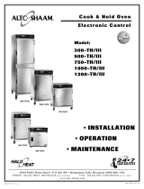
An identification tag is permanently mounted on
the cabinet. Make certain the model number and
marked electrical ratings match your order. Note
the serial number for your records.
If necessary, a proper receptacle or outlet config-
uration, as required for the individual equipment
model, must be installed by a licensed electrician in
accordance with applicable, local electrical codes.
The oven must be grounded in accordance with
requirement of the National Electrical Code or
applicable local codes.
The oven must be set to the line voltage provided by
your electric power supplier. The oven defaults to
240V. To change the voltage, refer to Section 6
- Service located in this manual.
The main power switch is located at the back of
the oven. After wiring and power connection has
been completed, turn the main power switch to the
“
ON” position. This switch can be left “ON” for daily
use, but should be turned “OFF” when cleaning,
performing maintenance or repairs to the unit.
Remember to position the oven so that the
power supply cord is easily accessible in case of an
emergency.
EXAMPLE
SERIAL NUMBER AND WARRANTY CODE
MAXIMUM RATED
WATTAGE
IDENTIFICATION MODEL NUMBER
MAXIMUM RATED VOLTAGE MAXIMUM RATED FREQUENCY
MODEL
SERIAL NO. WATTS
1 PH
VOLTS
xxx-xx
xxxx-xx xxxx
xx
HZxxx
AC
ALTO-SHAAM INC. MILW. WI. PAT. NO. 3521030
INSTALLATION REQUIREMENT!
FOR CORRECT OPERATION,
CONTROL MUST BE SET TO
MATCH THE POWER SUPPLY LINE.
Beeper
Port
Printer
Port
Main
Power
Switch
Cord
Inlet
Cord Replacement
Information Label
Hi-Limit
Reset
Software
ID Tag
Sample
Rating and
Certification
ID Tag
Single Cavity Oven
Back View
ON
OFF

O&C MANUAL #8311 • TH/III FAMILY
PG. 2
SECTION 1 INSTALLATION SECTION 1
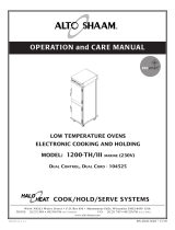
1200-TH/III Installation Requirements:
Permanent wiring for this model series
must be installed by a licensed electrician
in accordance with applicable, local
electrical codes.
Tether Attachment for Permanent Wiring:
A) A permanently connected appliance, with casters
attached, must be tethered to the building structure,
in two places, to limit movement of the appliance
without depending on or transmitting stress to the
electrical conduit.
B) A hole on each side of the rear center grill, lower
flange, is provided for attaching two tether cables.
The other end of each should be anchored to the wall
structure with hardware sufficient to withstand 200
pound pull. (1/16" aircraft cable and 1/4" x 2" lag
bolts are recommended.)
C) The appliance shall be installed using flexible conduit,
with system meeting requirements of National Electric
Code for appliance rating. International units should
meet national or country code.
Beeper
Ports
Upper
Lower
Printer
Ports
Upper
Lower
Power
Switch
Power
Inlet
Upper Cavity
Hi-Limit Reset
Upper Cavity
Software ID
Tag
Sample
Lower Cavity
Software ID
Tag
Rating and
Certification
ID Tag
Double Cavity Oven
Top Back View
Double Cavity Oven
Mid-Section Back View
Ambient
Chamber Fan
Holes for Lanyard Tether
Cord Attachment
Lower Cavity
Hi-Limit Reset
Cord Connection for Semi-Permanent Installation:
A) Use UL listed (or appropriate for country of
installation) grounding type plug with integral
cord grip that is rated for 250 Volts, 30
Amperes, Single Phase, and 10 gauge cord with
insulation system meeting codes for installation.
B) Conductors of supply cord must be connected to
terminal block marked L1 and L2 with greater
length for ground lead to center terminal
marked GND.

O&C MANUAL #8311 • TH/III FAMILY
PG. 3
SECTION 1 INSTALLATION SECTION 1
Oven Characteristics
The cabinet is equipped with a special, low-heat-density, heating cable. Through
the Halo Heat concept, the heating cable is mounted against the walls of the cooking
and holding compartment to provide an evenly applied heat source, controlled by an
oven sensor. The design and operational characteristics of the unit eliminates the need
for a moisture pan or a heat circulating fan. Through even heat application, the food
product is cooked evenly and capable of being held for longer time periods.
Printing
The electronic cook and hold oven is equipped with a serial data port for connec-
tion to a serial printer or PC terminal. This will provide temperature recording data
(HACCP protocol) as well as setup and diagnostic information. Refer to the section on
printing for additional details.
Start-Up
1. Before operating the oven, clean both the interior and exterior of the unit
with a damp cloth and any good alkaline or alkaline chlorinated based
commercial detergent at the recommended strength. Rinse surfaces by
wiping with a sponge and clean warm water to remove all deter-
gent residue. Wipe dry with a clean cloth or air dry.
2. Wipe door gaskets and control panel dry with a soft cloth.
3. Clean and install the oven side racks, oven shelves, and external
drip tray. Shelves are installed with curved edge toward the back
of the oven. Insert the drip pan on the
interior bottom surface of the oven.
4. Before operating the unit with product, become familiar with the
operation of the controls. Read the following "Control
Description" and "Operation" section of this
manual and operate the various control functions.
At no time should
the oven interior or exterior
be steam cleaned, hosed
down, or flooded with water
or liquid solution. Do not
use water jet to clean.
Severe damage or electrical
hazard could result voiding
the warranty.
Bumper, rubber, full perimeter w/casters
— 1000-TH/III . . . . . . . . . . . . . . . . . . . .44091
— 750-TH/III . . . . . . . . . . . . . . . . . . . . .44090
— 500-TH/III . . . . . . . . . . . . . . . . . . . . .44089
Carving Holders
— Prime Rib Holder . . . . . . . . . . . .HL-2635
— Ship Round Holder w/pan . . . . . . .4459
Casters, 3" (76mm) . . . . . . . . . . . . . . . .14227
Casters, 5" ( 127mm) . . . . . . . . . . . . . . . .4007
Drip Pan, Standard, w/drain and screen
— 1000, 1200-TH/III . . . . . . . . . . . . . . .14824
— 750-TH-III . . . . . . . . . . . . . . . . . . . . .14831
— 500-TH-III . . . . . . . . . . . . . . . . . . . . .14813
Drip Pan, Extra Deep
— 750, 1000, 1200-TH/III . . . . . . . . . . . .1115
Drip Pan, Extra Deep with Drain
— 1000, 1200-TH/III . . . . . . . . . . . . . . . .4932
Key Lock for Handle . . . . . . . . . . .LK-22567
Legs, 6" (152mm)
— 500, 750, 1000-TH-III . . . . . . . . . . . . .5205
Leg Kit Option, 1200-TH-III ONLY . . . .44093
Pocket Thermometer, °F . . . . . . . . .TH-3300
Pocket Thermometer, °C . . . . . . . . .TH-3412
Serial Printer & Cable Pkg
— 208-240V . . . . . . . . . . . . . . . . . . . . . .14218
— 230V . . . . . . . . . . . . . . . . . . . . . . . . . .14679
Serial Printer Paper . . . . . . . . . . . .PO-33397
Shelves, S/S Rib Rack
— 1000, 1200-TH/III . . . . . . . . . . . .SH-2773
— 750-TH/III . . . . . . . . . . . . . . . . . .SH-2743
Shelves, S/S Flat Wire
— 1000, 1200-TH-III . . . . . . . . . . . .SH-2325
— 750-TH-III . . . . . . . . . . . . . . . . . .SH-2324
— 500-TH-III . . . . . . . . . . . . . . . . . .SH-2326
Wire pan grid
— 1200, 1000, 750-TH-III . . . . . . . .PN-2115
➥18" X 26" (457mm x 660mm) Insert
OPTIONS and ACCESSORIES
This wall-friendly full perimeter bumper is
now offered as standard on the
1200-TH-III cook/hold oven.
It is offered as an option for the
Models 500, 750, and 1000-TH-III
cook/hold ovens.

O&C MANUAL #8311 • TH/III FAMILY
PG. 4
SECTION 2 CARE AND CLEANING SECTION 2
Under normal operating conditions, this oven will provide you with long and trouble-free
service. There is no preventative maintenance required, however, the following guidelines will
maximize the potential life and trouble-free operation of this oven.
Clean the Oven Daily
The cleanliness and appearance of this equipment will contribute considerably to
operating efficiency and savory, appetizing food. Good equipment that is kept clean
works better and lasts longer.
1. Turn power switch located at the back of the oven to the "OFF" position. Let unit cool.
2. Remove all detachable items such as wire shelves, side racks, and drip pan. Clean
these items separately.
3. Wipe the interior metal surfaces of the oven with a paper towel to remove loose
food debris.
4. Clean interior with a damp cloth or sponge and any good alkaline or alkaline
chlorinated based commercial detergent at the recommended strength.
5. Spray heavily soiled areas with a water soluble degreaser and let stand for
10 minutes, then remove soil with a plastic scouring pad.
NOTE: Avoid the use of abrasive cleaning compounds, chloride based cleaners,
or cleaners containing quaternary salts. Never use hydrochloric acid
(muriatic acid) on stainless steel.
6. Wipe control panel, door vents, door handles, and door gaskets thoroughly
since these areas harbor food debris.
7. Rinse surfaces by wiping with sponge and clean warm water.
8. Remove excess water with sponge and wipe dry with a clean cloth or air dry.
Leave doors open until interior is completely dry. Replace side racks and shelves.
9. Wipe door gaskets and control panel dry with a clean, soft cloth.
10. Interior can be wiped with a sanitizing solution after cleaning and rinsing.
This solution must be approved for use on stainless steel food contact surfaces.
11. To help maintain the protective film coating on polished stainless steel, clean the
exterior of the cabinet with a cleaner recommended for stainless steel surfaces.
Spray the cleaning agent on the cloth and wipe with the grain of the stainless steel.
12. Clean any glass with a window cleaner.
Always follow appropriate state or local health (hygiene) regulations regarding all
applicable cleaning and sanitation requirements for equipment.
Clean the Probes Daily
Remove all food soil from probes. Wipe entire probe and cable assembly with warm
detergent solution and a clean cloth. Remove detergent by wiping each probe and
cable with clean rinse water and a cloth. Wipe probes and probe brackets with
disposable alcohol pad or sanitizing solution recommended for food contact
surfaces. Allow probe and cable to air dry in probe holding bracket.
Check the Cooling Fan in the Oven Control Area
While the oven is warm, check that the cooling fan in the oven control area
is functioning. The fan is located at the back of the unit, toward the top.
Model 1200-TH/III has an additional ambient chamber fan located in the back,
centered between the top and bottom cavity. Both fans must be functioning
in order for the oven to work properly.
Check Overall Condition of the Oven Once a Month
Check for physical damage and loose screws. Correct any problems before
they begin to interfere with the operation of the oven.
MAKE CERTAIN
THE UNIT IS
DISCONNECTED
FROM THE
POWER
SOURCE BEFORE
CLEANING

O&C MANUAL #8311 • TH/III FAMILY
PG. 5
SECTION 3 CONTROL SECTION 3
1. On/Off Key
The ON/OFF control system key operates the
functions of the control panel. If there is any
power loss during operation, the
ON/OFF indicator
light will flash. To clear, push key and release.
2. Cook Key — Temperature range 200° to 325°F (93° to 162°C)
Used to select cooking mode and to review the
cook temperature setting.
3. Time Key — Maximum time 24 hours
Used to select cook time and to review set time.
4. Probe Key — Temperature range 50° to 195°F (10° to 91°C)
Used to select internal product probe temperature
mode and to review probe temperature setting.
5. Hold Key — Temperature range 60° to 205°F (15° to 96°C)
Used to select food holding mode and to review set
holding temperature.
6. Lock Indicator
When illuminated, this symbol indicates settings
used in the cooking sequence are locked and can-
not be changed.
7. Halo Heat Indicator
When the oven is preheating, the Halo Heat indi-
cator will illuminate during preheating and
remain steady until the oven reaches the set
cooking temperature. When the temperature has
stabilized, the indicator will illuminate periodi-
cally as the oven calls for heat.
8. Oven Preheat Light
Illuminates until the oven is preheated.
9. LED Display
Indicates interior oven air temperature, internal
product probe temperature, time or, when used
in conjunction with other keys, will review origi-
nal cooking, holding and probe temperature set-
tings. The display will also indicate various pro-
gramming and diagnostic information.
10. Ready Indicator Light
Illuminates when the oven has finished preheating.
11. UP and DOWN Arrows
Used to increase or decrease set time, including
cooking, holding and probe temperature settings.
12. Start Key
Used to initiate a selected mode sequence when
pressed and released. You may stop any mode of
operation by pressing and holding the Start Key
until you hear a beep.
13. Green Indicator Lights
Located within each function key, the green
light functions as an operator prompt indicating
additional operator action is required and also
identifies current mode of operation.
14. Amber Indicator Lights
Located below the Cook, Time, Probe and Hold
Keys, these indicators will illuminate to identify
the current mode of operation and allows the
operator to identify the information currently
shown in the LED display.
15. Preset Program Keys
Provides memory storage and operation of up to
eight operator set cooking programs for specific
products (A thru H). I enables locking abilities.
16. Cancel Key
Used to erase a program from memory storage.
PRESETS
ABCDEFGHI CANCEL
CONTROL FEATURES
Do not use the oven if the controls are not properly functioning. Refer to the Trouble
Shooting Guide located in this manual or call an authorized service technician.
IMPORTANT

O&C MANUAL #8311 • TH/III FAMILY
PG. 6
SECTION 3 CONTROL FEATURES SECTION 3
OVEN BEEPING is used to indicate a yes or no response to operator input.
Beeps also indicate mode changes and error conditions.
One brief beep indicates a yes (enabled) response to the information entered into the control.
Two brief beeps indicate a no (disabled) response to the information entered into the control.
A beep that lasts for one second indicates an oven mode transition. Example: Preheat to Ready-Start.
Three brief beeps indicate the oven is in the ready mode for product loading and start-up.
Four brief beeps indicate an existing fault condition. Refer to the Trouble Shooting section of this manual.
Beeper volume can be changed. With the oven in the
off mode, press and hold the Up Arrow Key and the Preset Menu "C"
Key at the same time for a minimum of four seconds. The oven will begin to beep in varying tones. Release both keys when
the desired volume is reached.
AUDIBLE SIGNALS
Turn the Oven Control Panel Off:
Press and hold the ON/OFF Key for three seconds. Oven will
beep. The
ON/OFF indicator light will go out.
Stop an Operation:
Press and hold the Start Key for several seconds until the control
beeps, indicating the operation has been cancelled. The oven will
remain in a power-on state.
Arrow Keys:
Cook, Hold and Probe Temperature set points can be adjusted by
1° when pressing the Arrow Keys. To change a set point more
rapidly,
press and hold the Arrow Key along with the key for the
temperature function, and the temperature changes in steps of
10°F or 5°C.
The
Time setting is adjusted in increments of one minute by press-
ing the Arrow Keys. To make adjustment in steps of ten minutes,
press and hold the Time Key and Arrow Key at the same time.
Probe Usage:
When the probe is left in the probe bracket, the LED temperature
display will indicate the ambient air temperature inside the oven.
To use the probe for cooking remove it from the bracket and wipe
the full length of the metal probe with a disposable alcohol pad to
clean and sanitize before using.
Only the tip of the probe senses the internal product temperature,
therefore, it is important the tip be placed correctly in the product
for internal temperature accuracy. Push the probe tip halfway into
the product, positioning the tip at the center of the food mass.
When inserting the probe into solid foods such as meat roast or
poultry breasts, push the probe in from a straight downward posi-
tion or in from the side to the center position. If placing into a
semi-liquid or liquid product, the probe cable must be secured to
keep the probe positioned properly. Do not let the probe tip touch
the edges, bottom or side of a container. Tape the probe cable to
the lip or edge of the container.
Display High/Low Probe Temperatures:
To observe the recorded maximum or minimum probe tem-
perature during a cooking program press the following keys:
Highest Temperature: Press Probe Key and Up Arrow Key
at same time.
Lowest Temperature: Press Probe Key and Down Arrow
Key at same time.
Halo Heat Indicator:
When the oven is preheating the Halo Heat indicator light
will remain illuminated until it reaches the set cook tempera-
ture. Once the temperature has stabilized, this indicator will
illuminate periodically as the oven calls for heat.
Green and Amber Indicators:
Each program key includes a green light which indicates a
requirement for additional programming by the operator or
the current operational state of the oven.
The Cook, Time, Probe, and Hold keys include an amber
indicator light to identify the information being displayed.
Green
Amber
Power Fail Detect:
If the power were to fail for any reason while heating, the
control will retain, in memory, the programmed operating
conditions. When power is restored, the control will resume
operating from the point where it was interrupted and the
ON/OFF indicator light will flash, indicating that such an
event did occur. The operator can turn off the flashing light
by pressing the
ON/OFF key. It is strongly recommended
that if such an event has occurred, ensure that the food is
safe for consumption according to local health regulations.
OPERATING FEATURES & FUNCTIONS
TIME
●

O&C MANUAL #8311 • TH/III FAMILY
PG. 7
SECTION 3 CONTROL OPERATION SECTION 3
Cook by Time:
Press and release control ON/OFF key.
• The green indicator light on the ON/OFF key will illuminate.
• The oven will beep for one second.
• The oven will begin operating in the hold mode.
• The amber hold indicator will illuminate.
• The previously set hold temperature will be displayed.
Press the Hold Key.
➥To change the hold temperature, press the Up or Down Arrow Keys.
Note: If the oven is being used for hot food holding only, adjust the
set holding temperature. Do not press the Cook, Time, or Probe keys.
Press Cook Key to preheat.
• The green indicator light on the COOK Key will illuminate.
• Last set cooking temperature will be displayed.
➥To change the cook temperature, press the Up or Down Arrow Keys.
• The green indicator light on the Time Key and on the Probe Key alternately flash.
Press Time Key.
• The green indicator light on the TIME Key will illuminate.
• Last set time is displayed.
➥To change the cook time, press the Up or Down Arrow Keys.
• The green indicator light on the Time Key will illuminate.
• Halo Heat and Pre-Heat indicator will illuminate.
➥The oven is automatically programmed to preheat to the cook temperature.
• The oven will beep when preheated and the preheat indicator light will go out.
• Both the Ready and Start indicator lights will flash.
➥The set cook temperature will be maintained by the oven and appear in the display
while in the ready/start mode.
Load the food inside oven and close the oven door.
Note: The oven will beep 3 times every 25 seconds until the oven is loaded and the
Start Key pressed.
Press and release Start key.
• The oven will beep.
• The green indicators for power, cook, time, and start will illuminate.
• The display will alternate between showing the set cook temperature and the
remaining time.
COOK
• The oven will beep at the end of the timed cooking cycle.
• The green indicator for cook will remain illuminated.
• The display will alternate between showing the set hold temperature and the
amount of time the product has remained in the holding mode.
HOLD
• The Ready indicator light will illuminate after 2 hours in the hold mode.
Note: The ready indicator does not necessarily indicate a product-ready state. For best
results, the product must remain in the oven at the set holding temperature for
the minimum number of hours indicated in the individual cooking instructions.
• The oven will remain operating in the hold mode until the control
ON/OFF Key is pressed.
ON/OFF
START
HELPFUL HINT
To avoid prolonged
preheat times between
loads, leave the oven
in the hold mode.
Cold food for rethermalization
or reheating must never be
added to the oven
while hot food is being held.

O&C MANUAL #8311 • TH/III FAMILY
PG. 8
SECTION 3 CONTROL OPERATION SECTION 3
ON/OFF
START
Cook by Probe:
Press and release control ON/OFF key.
• The green indicator light on the ON/OFF key will illuminate.
• The oven will beep for one second.
• The oven will begin operating in the hold mode.
• The amber hold indicator will illuminate.
• The previously set hold temperature will be displayed.
Press the Hold Key.
➥To change the hold temperature, press the Up or Down Arrow Keys.
Note: If the oven is being used for hot food holding only, adjust the set holding
temperature. Do not press the Cook, Time, or Probe keys.
Press Cook Key to preheat.
• The green indicator light on the COOK Key will illuminate.
• Last set cooking temperature will be displayed.
➥To change the cook temperature, press the Up or Down Arrow Keys.
• The green indicator light on the Time Key and on the Probe Key
alternately flash.
Press Probe Key.
• The green indicator light on the PROBE Key will illuminate.
• Last set internal product temperature is displayed.
➥To change the internal product temperature, press the Up or Down Arrow Keys.
• The green indicator light on the Probe Key will illuminate.
• Halo Heat and Pre-Heat indicator will illuminate.
➥The oven is automatically programmed to preheat to the cook temperature.
• The oven will beep when preheated and the preheat indicator extinguished.
• Both the Ready and Start indicator lights will flash.
➥The set cook temperature will be maintained by the oven and appear in the display
while in the ready/start mode.
Load the food inside oven. Remove probe from its bracket, wipe the probe tip with a disposable
alcohol pad and insert probe properly into the product. Close the oven door.
Note: Oven will beep 3 times every 25 seconds until oven is loaded and Start Key pressed.
Press and release Start key.
• The oven will beep.
• The green indicators for power, cook, probe, and start will illuminate.
• The display will alternate between showing the set cook temperature and the
elapsed time.
COOK
• The oven will beep when the set probe temperature has been reached.
• The green indicator for cook will remain illuminated.
• The display will alternate between showing the set hold temperature and the
amount of time the product has remained in the holding mode.
HOLD
• Ready indicator light will illuminate after 2 hours in the hold mode.
Note: The ready indicator does not necessarily indicate a product-ready state. For best
results, the product must remain in the oven at the set holding temperature for
the minimum number of hours indicated in the individual cooking instructions.
• The oven will remain operating in the hold mode until the control ON/OFF Key is pressed.
Cold food for
rethermaliza-
tion or reheat-
ing must never
be added to the
oven
while hot food
is being held.

O&C MANUAL #8311 • TH/III FAMILY
PG. 9
SECTION 3 CONTROL OPERATION SECTION 3
Preset Menu Keys:
Alto-Shaam Cook and Hold ovens allow the operator to set up to eight cooking programs. Each cooking pro-
gram can be preset in any program mode to cook by time or internal product temperature. Cooking programs
are recalled and stored using the Preset Keys labeled "A through H." These keys, along with the key labeled "I"
share additional functions described in the "User Options" section of this manual.
Programming a Cooking Program
Select the product to be programmed and begin programming with the oven control power off.
Press and release control ON/OFF key. The oven will beep for one second and power to the unit
will be indicated by an illuminated green indicator light located in the upper left corner of the
ON/OFF key. The oven will begin operating in the hold mode. The amber hold indicator will
be illuminated and the last set hold temperature will be displayed.
Press Hold Key. To change the hold temperature, press the Up or Down
Arrow Keys.
Press Cook Key. Oven preheat indicator will illuminate and the last set cooking tempera-
ture is displayed. To change the cook temperature, press the Up or Down Arrow Keys.
To cook by time — press the Time Key. Last set cooking time is displayed.
To change the set time, press the Up or Down Arrow Keys. The green Time indicator
will illuminate.
To cook by probe — press the Probe Key. Last set internal product temperature is displayed.
To change the set temperature, press the Up or Down Arrow Keys. The green Probe indicator
will illuminate.
The oven preheat indicator will illuminate. Oven is now in the preheat mode and is
automatically programmed to preheat to the cook temperature.
Select a letter code for the product programmed by the previous steps. Press and hold the
selected Preset key until you hear a brief, four second beep. The letter key program indicator
light will illuminate and the product programmed is now stored in memory for the specific
letter key pressed. Additional programs can be stored in the remaining Preset Keys if not
previously programmed.
Note: The last Preset Key used will be the oven cooking run sequence for the next product to
be programmed. Settings can be manually changed for the next product and an alternate pre-
programmed letter key selected.
Erasing a Cooking Program
To erase a program you no longer use or revise a previously programmed Preset Key the oven must be in
either the power-up hold mode or in the preheat mode. The oven cannot be running a Preset Menu program.
When the oven is in the power-up hold mode or in the preheat mode, press and hold both the Cancel Key and
the appropriate letter Preset Key to be erased. The oven will beep in approximately four seconds and the pro-
gram's indicator light will go out to indicate the program has been erased.
ON/OFF
— or —
PRESETS
A
After programming a specific product into memory in a programmable preset
key, it is very important to make a written permanent record of the product and
the program letter assigned. Menu card (PE-23384) is provided for this purpose.
IMPORTANT

O&C MANUAL #8311 • TH/III FAMILY
PG. 10
SECTION 3 CONTROL OPERATION SECTION 3
Cook Using Preset Menu Keys:
Press and release control ON/OFF key.
• The green indicator light on the ON/OFF key will illuminate.
• The oven will beep for one second.
• The oven will begin operating in the hold mode.
• The amber hold indicator will illuminate.
• The previously set hold temperature will be displayed.
• Preset Keys with stored cooking programs will have green indicator illuminated.
Press Desired Preset Key (A through H)
• Halo Heat and Pre-Heat indicator will illuminate.
➥The oven is automatically programmed to preheat to the cook temperature programmed.
• The oven will beep when preheated and the preheat indicator will go out.
• Both the Ready and Start indicator lights will flash.
➥ The set cook temperature will be maintained by the oven and appear in the display
while in the ready/start mode.
Load the food inside oven. If cooking by probe, remove probe from its bracket, wipe the probe
tip with a disposable alcohol pad and insert probe properly into product. Close the oven door.
Note: The oven will beep 3 times every 25 seconds until the oven is loaded and the Start
key pressed.
Press and release Start Key.
• The oven will beep.
• The green indicators for power, cook, probe or time, and start will illuminate.
• If programmed to cook by time, the display will alternate between showing the set cook
temperature and the time remaining.
• If programmed to cook by probe, the display will alternate between showing the set cook
temperature and the elapsed time.
COOK
• The oven will beep when the set probe temperature has been reached or set time has elapsed.
• The green indicator for cook will remain illuminated.
• The display will alternate between showing the set hold temperature and the
amount of time the product has remained in the holding mode.
HOLD
• The Ready indicator light will illuminate after 2 hours in the hold mode.
Note: The ready indicator does not necessary indicate a product-ready state. For best
results, the product must remain in the oven at the set holding temperature for
the minimum number of hours indicated in the individual cooking instructions.
• The oven will remain operating in the hold mode until the control ON/OFF Key is pressed.
ON/OFF
PRESETS
A
START

O&C MANUAL #8311 • TH/III FAMILY
PG. 11
SECTION 4 PRINTER OPTION SECTION 4
Connecting the Printer to the Oven
1. On the printer, using your printer operation manu-
al, locate the dip switch panel on the lower left
side. Remove the panel cover and set all switches
to the up (on) position. The printer should be
shipped with all switches in the up position. Set
the second switch from the right to the down (off)
position. Set the fifth switch from the left to the
down (off) position. If printing in a language other
than English, consult Table A for appropriate
switch settings.
2. Locate the serial data port on the rear panel of the
oven, just to the left of the cooling fan inlet. Attach
the serial data cable to this port. Using the printers
operation manual, locate its serial data port and
connect the serial data cable.
3. The printer's power switch is located on the bottom
right side. Turn on the printer. Ensure that the
printer's green power and on-line indicators are
illuminated. Refer to Chapter Three of the printer
operation manual if these are not illuminated.
4. Turn on the cook and hold oven and you will see a
print out of some of the oven's basic configuration.
The electronic cook and hold oven is equipped with a serial data port for connection to
an optional serial printer in order to obtain a printed report of temperature recording data
(HACCP protocol) as well as setup and diagnostic information. The control has enough
memory to store 120-150 temperature samples as a total for all reports combined. Temperature
samples are read through the product probe. Only the tip of the product probe senses the inter-
nal product temperature, therefore, it is important the tip be placed correctly in the product for
accuracy. These reports can be printed in English, French, German or Spanish.
A 9-pin serial data port is located at the back of the oven near the cooling fan. This port can
be used to connect the serial data printer to the oven in order to take advantage of the data
reporting capabilities.
In order to ensure the proper cable and the correct printer switch settings, we recommend
purchasing your printer from Alto-Shaam:
Serial Printer & Cable Package — 125/208-240V . . . . . . . . Part # 14218
230 V . . . . . . . . . . . . . . Part # 14679
Serial Printer Paper . . . . . . . . . . . . . . . . . . . . . . . . . . . . Part # PO-33397
The printers are shipped with a users manual. It is recommended that you read the first
four chapters in order to understand how to operate and service the printer. This is necessary
in order to load the paper, change the printer ribbon, and understand it's operation. To begin
printer set up, you must first load the paper, print ribbon and connect the power supply. Place
the printer in a convenient spot near the oven.
Do NOT place the printer on top of the oven on the left side. The paper
may block the air inlet fan and cause overheating of the electronic controls.
IMPORTANT
Switch Position Comment
1-1 Up
1-2 Down
1-3 Up
1-4 Up
1-5 Down Flow Control:
X-ON / X-OFF
1-6 Up
1-7 Up
1-8 Up
2-1 Up Up: English
Down: French
German
Spanish
2-2 Up Up: English
French
Spanish
Down: German
2-3 Up
2-4 Up
Table A

O&C MANUAL #8311 • TH/III FAMILY
PG. 12
SECTION 5 USER OPTIONS SECTION 5
D. Fahrenheit or Celsius Selection
With the control in the off mode, press and
hold the Up Arrow Key along with the
Preset "D" Key for two seconds. Oven will
beep. The display will indicate the
temperature scale selected.
E. Language Choices
To change the language that the oven uses for print-
ing to a printer or PC terminal, with the control in
the off mode, press and hold the Up Arrow Key
along with the Preset "E" Key for two seconds. Each
time you press this key combination you will hear a
brief beep and the oven will print the next available
language. Continue pressing this key combination
until you have reached the language you desire.
The languages available are English, French, German
and Spanish.
F. Printing Reports
To print summaries of previous cooking programs
to a printer or PC terminal, press and hold the Up
Arrow Key, along with the Preset "F" Key for two
seconds. You will hear a brief beep and the oven
will print summaries of the last seven cooking
sequences. You cannot print report summaries if the
oven is currently in on-line printing during a cook-
ing sequence.
G. On-line Printing
On-line printing allows you to print a running
record of time, probe temperature and mode during
oven operation to a printer or PC terminal. With the
control in the off mode, toggle between on-line and
off-line status by pressing and holding the Up
Arrow Key along with the Preset "G" Key for two
seconds. One brief beep indicates that you are now
in the on-line printing state. Two beeps indicates
the off-line printing state. A status message will be
printed indicating the change to on-line printing.
"On-line 1" indicates that samples will be taken at
one minute intervals. "On-line 5" indicates a five
minute interval between samples.
H. On-line Printing Intervals
You are able to control the time interval at which
the on-line data is recorded. You can set the inter-
vals at one minute or at five minutes. Regardless of
the interval you select, the oven will always print at
ten minute intervals while in Preheat, Ready Start
mode and after 121 minutes in the Hold mode. With
the oven in the off mode, toggle between the one
minute or five minute interval choice by pressing
and holding the Up Arrow Key along with the
Preset "H" Key for two seconds. One brief beep
indicates that samples will be printed in one minute
intervals. Two beeps indicates printing in five
minute intervals.
C. Beeper Volume Selection
With the control in the off mode,
press and hold the Up Arrow Key along
with the Preset "C" Key for a minimum of four
seconds. Oven will begin to beep in varying tones.
Release both keys when the desired volume is reached.
PRESETS
ABCDEFGHI CANCEL
Beeper
Volume
°C/°F
Selection
Reports
Sample
Rate Interval
Language
Choices
Online
Preset
Lock

O&C MANUAL #8311 • TH/III FAMILY
PG. 13
SECTION 5 USER OPTIONS SECTION 5
I. Preset Keys Lock and Unlock
Preset Keys A through H can be locked in order to
prevent storing, altering or erasing a program.
To lock the preset keys, press and hold the "I" Key
for four seconds. Oven will beep. Release the “I”
key. The green indicator on the "I" key will illuminate.
Oven Preset Keys A through H are now locked.
Note: Only the oven Preset keys A through H are
affected by this lock-out in order to also allow
the oven to be used with the unprogrammed
Cook, Probe, or Hold modes.
To unlock the preset keys, press and hold the Cancel
Key along with the "I" Key for four seconds. You
will hear a brief beep. Release all keys. The green
indicator on the "I" key will extinguish. The oven
preset keys are now unlocked.
Control Panel Lock and Unlock
The control panel can be locked at any time in order
to prevent inadvertent or accidental setting changes.
To lock the control panel, press and hold the Up
Arrow Key and then press the ON/OFF Key. You will
hear a brief beep and the panel lock indicator will
illuminate. Release all keys. The oven's
control panel is now locked.
Note: The control panel is now fully locked with the
exception of the ON/OFF Key and Arrow keys.
You will be unable to turn the oven control off
at this point.
To unlock the control panel, press and hold the
Down Arrow Key and then press the ON/OFF Key.
You will hear two brief beeps and the panel lock
indicator will extinguish. Release all keys. The
panel is now unlocked and ready for normal use.
Lock
Indicator
PRESETS
ABCDEFGHI CANCEL
Preset
Lock
Cold food for rethermalization or reheating
must never be added to the oven
while hot food is being held.

O&C MANUAL #8311 • TH/III FAMILY
PG. 14
SECTION 6 SERVICE SETUP SECTION 6
Determine Correct Voltage and Unit Setup
1. Verify voltage at outlet or junction box. Make
sure that the voltage is checked between L1 and L2
and from each leg to ground. Each reading should
be within 5% of each other.
2. Verify unit setup by beginning in the
off mode.
Hold the Cook Key and the Down Arrow Key at
the same time until you hear a brief beep. If you
hear two brief beeps, the oven is not in the off mode.
The oven will display it's setup information.
Option Code Indicates oven model
programming (see Table B)
Line Voltage Indicates set voltage
Software Phase Alph, Beta or Prod
Software Version Operating software version
example: 2.10
Printer / Lock State Indicates current status
Left digit: On-line printing 1 = on
0 = off
Third digit: On-line Interval 1 = 5"
0 = 1"
Second digit: Panel Lock 1 = on
0 = off
Right digit: Preset Lock 1 = on
0 = off
Example: 1101 = on-line printing,
5 minute printing interval, panel
lock off, preset lock on
Option Model Max. Temp
Code Number °F°=°C
12 500-TH/III - 120V 325=163
13 500-TH/III - 120V 250=121
16 CH-50/III - 120V 325=163
18 500-TH/III 325=163
19 500-TH/III 250=121
22 CH-50/III 325=163
34 750-TH/III 325=163
35 750-TH/III 250=121
38 CH-75/III 325=163
58 767-SK/III 325=163
59 767-SK/III 250=121
66 1000-TH/III 325=163
67 1000-TH/III 250=121
70 CH-100/III 325=163
82 1200-TH/III UPPER 325=163
83 1200-TH/III UPPER 250=121
86 CH-120/III UPPER 325=163
98 1200-TH/III LOWER 325=163
99 1200-TH/III LOWER 250=121
102 CH-120/III LOWER 325=163
Table B
Table C
INSTALLATION REQUIREMENT!
FOR CORRECT OPERATION,
CONTROL MUST BE SET TO
MATCH THE POWER SUPPLY LINE.
Changing the Voltage Setting:
Password 3838
With the oven in the off mode, push and hold
the Up and Down Arrow Key at the same time.
After 4 seconds, the display will show a zero
along with 3 dashes. Using the Up Arrow Key,
toggle up until the display shows a 3, then
push the Start Key. Using the Down Arrow
Key, toggle down until the display shows a 8
and push the Start Key. Using the Up Arrow
Key, toggle up until the display shows a 3 and
push the Start Key. Using the Down Arrow
Key, toggle down until the display shows an 8
and push the Start Key. The current set volt-
age will display.
If the setting needs to be changed, use the Up
or Down Arrow Key to select the proper volt-
age as measured at the outlet and then push
the Start Key. The voltage is now set for the
supplied voltage.
The control defaults to 240V on all models except
the 500-TH/III, 125V model. The default for this
unit is 120V. The oven control must be set to the
line voltage provided by your electric power sup-
plier in order to perform correctly. As an added
benefit, the unit will operate economically with an
average wattage draw much lower than those stat-
ed on the rating tag as shown below in Table C.
Voltage Model Average Power
Setting Number Draw (Watts)
200 500-TH/III 1880
750-TH/III 2710
1000-TH/III 2710
1200-TH/III 5420
208 500-TH/III 2030
750-TH/III 2930
1000-TH/III 2930
1200-TH/III 5860
230 500-TH/III 2075
750-TH/III 2860
1000-TH/III 2860
1200-TH/III 5720
240 500-TH/III 2030
750-TH/III 2930
1000-TH/III 2930
1200-TH/III 5860

O&C MANUAL #8311 • TH/III FAMILY
PG. 15
SECTION 6 SERVICE SECTION 6
Unit Setup
Once you've verified the unit option code using the
directions listed on the previous page, and you've
found that the option code does not correspond
with the actual model number stated in Table B,
you will need to change the unit option code.
Initializing the Control
Password 1818
If the control appears to be operating correctly but
there is no 3.5 - 5 VDC at the solid state relay across
4- and 3+, attempt to reinitialize the control before
replacing it. Perform this procedure the same as
you would to set the voltage or option code.
Instead enter 1818 and then hit start. The display
will go blank. Proceed to program the correct volt-
age and option code and test for power. If there is
still no power to the solid-state relay, check to verify
the wiring is correct. If everything checks out, the
control may be defective.
SERVICING INTERNAL ELECTRICAL COMPONENTS
This section is provided for the assistance of
qualified technicians only and is not intended
for use by untrained or unauthorized service
personnel.
If your Alto-Shaam® unit is not operating proper-
ly, check the following before calling your
Authorized Alto-Shaam® Service Agent:
☛ Check the power flow to the unit.
Plug in outlet? Fuse OK?
Circuit breaker switch at back of unit turned on?
Do not attempt to repair or service the
Cook and Hold unit beyond this point.
Contact Alto-Shaam® for the nearest
authorized service agent. Repairs made
by any other service agents without prior
authorization by Alto-Shaam® will void the
warranty on the unit.
Changing the Unit Option Code:
Password 2828
With the oven in the off mode, push and hold
the Up and Down Arrow Key at the same time.
After 4 seconds, the display will show a zero
along with 3 dashes. Using the Up Arrow Key,
toggle up until the display shows a 2, then
push the Start Key. Using the Down Arrow
Key, toggle down until the display shows a 8
and push the Start Key. Using the Up Arrow
Key, toggle up until the display shows a 2 and
push the Start Key. Using the Down Arrow
Key, toggle down until the display shows an 8
and push the Start Key. The current config-
ured option code will display.
Use the Up or Down Arrow Keys to select the
proper option code from Table B and then
push the Start Key.
Option Model Max. Temp
Code Number °F°=°C
12 500-TH/III - 120V 325=163
13 500-TH/III - 120V 250=121
16 CH-50/III - 120V 325=163
18 500-TH/III 325=163
19 500-TH/III 250=121
22 CH-50/III 325=163
34 750-TH/III 325=163
35 750-TH/III 250=121
38 CH-75/III 325=163
58 767-SK/III 325=163
59 767-SK/III 250=121
66 1000-TH/III 325=163
67 1000-TH/III 250=121
70 CH-100/III 325=163
82 1200-TH/III UPPER 325=163
83 1200-TH/III UPPER 250=121
86 CH-120/III UPPER 325=163
98 1200-TH/III LOWER 325=163
99 1200-TH/III LOWER 250=121
102 CH-120/III LOWER 325=163
Table B

ILLUSTRATION B.
FRONT VIEW
BACK VIEW
ILLUSTRATION C.
R.T.V. SEAL
SCREW LOCATIONS
CIRCUIT BREAKER
SWITCH
ILLUSTRATION A.
SIDE VIEW
SCREW LOCATIONS
I.D. TAG
PROVIDED SOFTWARE UPGRADE
I.D. TAG (TO BE PLACED HERE)
BONNET POSITION
IN TIP CLIPS
O&C MANUAL #8311 • TH/III FAMILY
PG. 16
SECTION 6 SERVICE SECTION 6
A. No power. Display will not light.
1. Verify that power is available at the outlet or junction box.
2. Verify that the circuit breaker switch on the back of the
unit is turned on.
3. Verify that the power cord is not open. Check continuity
with a VOM meter.
4. If the above steps check out okay, you'll need to
remove the top bonnet assembly. Disconnect electrical
power to the unit by turning off the circuit in the main
supply panel. Remove the screws described in
Illustrations A. through C. After screws have been
removed, gently lift bonnet, paying close attention not to
pull on wiring connections. Turn bonnet onto its left side
(when viewed from the front) as shown in Illustration B.
Slide the edge of the bonnet under the 2 security clips.
Reconnect electrical power to the unit.
a) Test for power at the load side of the circuit breaker.
See Figure 1. If ok, proceed to step b. If there is no
power, replace the defective circuit breaker.
b) Test for power at the load side
of the two filters. See Figure 2.
If ok, proceed to step c. If there
is no power, replace the defective
filter.
TROUBLE SHOOTING INTERNAL ELECTRICAL COMPONENTS
Load Side
Load Side
Figure 1
Figure 2
This section is provided for
the assistance of qualified
technicians only and is not
intended for use by
untrained or unauthorized
service personnel.
Do not replace any elec-
trical components with-
out first disconnecting
electrical power to the
unit by
turning off the circuit breaker in the
main supply panel. A warning sign
should be posted on the panel indicating
the oven is being serviced and that the

O&C MANUAL #8311 • TH/III FAMILY
PG. 17
SECTION 6 SERVICE SECTION 6
4. c) Check for power at the secondary side of the
transformer. The voltage reading should be
approximately 20 VAC at points 67 and 72
indicated on Figure 3. If the correct voltage
is not present, the transformer is defective.
d) Disconnect electrical power to the unit by turn-
ing off the circuit in the main supply panel.
Check the two inline fuse assemblies. Using a
VOM meter, remove one end of the fuse assembly
and check for continuity. See Figure 3. If the fuse
shows that it is open, then replace the bad fuse
assembly. If all the above tests (1-4) check out
okay, a defective control is the probable cause.
B. Display is lit and unit calls for heat, but unit
is not heating; or Error Code E30
1. Check to verify that the high limit switch located at
the rear of the bonnet, next to the cord inlet has not
been tripped. If it has been tripped, reset by either
pressing in the red button or by flipping up the green
tab. After resetting, the cause of the high limit trip
must be corrected. If the high limit switch will not
reset, the high limit switch is defective and must be
replaced. This is a safety device and must not
be jumped out or removed from the circuit.
2. Disconnect electrical power to the unit by turning
off the circuit in the main supply panel. Locate the
cable connections in either the front left corner or the
right rear corner of the unit and test each cable to
ground, using a VOM meter. Any resistance reading
to ground will indicate a shorted or open cable to
ground and the cable will need to be replaced. If this
checks out okay, proceed to step 3.
3. Reconnect electrical power to the unit. Check the
solid state relay mounted on the metal heat sink.
With the unit circuit breaker switch on
and the
control in the off mode
, using a VOM meter set to the
AC volt scale, check across the closure terminals #1
and #2. See Figure 4. There should be line voltage
(200-240 VAC) present. With the VOM meter set on
the DC volt scale, check across the trigger terminals #3
and #4, taking care to observe polarity. There should
be less than 1 volt DC current present. If not, the
solid state relay is defective.
4. On the same solid state relay, with the unit in the
preheat mode and using a VOM meter set to the DC
volt scale, check across the trigger terminal #3 and #4,
taking care to observe polarity. See Figure 5. There
should be a reading of between 3.5 and 5 volt DC
present. With the VOM meter on the AC volt scale
and checking across the closure terminal #1 and #2,
there should be less that 1 volt AC current present.
If not, the solid state relay is defective.
TROUBLE SHOOTING INTERNAL ELECTRICAL COMPONENTS CONTINUED
Figure 3
Figure 4
Secondary
Side
Line Voltage: 200-240 VAC
Figure 5
3.5 to 5 VDC

O&C MANUAL #8311 • TH/III FAMILY
PG. 18
SECTION 6 SERVICE SECTION 6
DISPLAY ERROR CODES
1. "E10"
Oven Fault under
temperature.
2. "E11"
Oven Fault over
temperature.
3. "E21"
Food probe fault over
temperature.
4. "E30"
Slow heating rate.
5. "E31"
Slow cooling rate.
POSSIBLE CAUSE
A. Frozen food product placed in
oven.
B. Air temperature sensor defective.
C. Voltage option incorrect.
A. Heating cable shorted to ground.
B. Air temperature sensor defective.
C. Failed solid state relay.
A. Food probe defective.
A. Oven door open.
B. Door gasket defective or
door out of adjustment.
C. Oven preheat was skipped.
D. Line voltage incorrect, voltage
option on control not pro-
grammed properly.
E. Defective air sensor or product
probe.
F. Defective solid state relay.
G. Bad wire connections or
open heating cable.
A. Failed solid state relay.
B. Defective air temperature sensor.
C. Shorted or grounded
heating cable.
REMEDY
Thaw food prior to placing in oven.
Test air sensor by placing sensor in ice
water bath and using an ohmmeter set on
the ohm scale. The reading should be
approximately 100 ohms resistance. If the
sensor tests out and there are bullet connec-
tors on the leads, cut off bullet connectors,
strip back the insulation 1/2", slide a piece
of heat shrink tubing over the wire, twist the
wires together and solder. Slide the heat
shrink tubing over the soldered connection
and heat in order to shrink material.
Change the voltage setting, referring to the
instructions in Section 6, Service Setup.
Replace heating cable.
Test air sensor using remedy instructions
above for 1B.
Replace solid state relay.
Test food probe by placing in ice water bath
and using an ohmmeter set on the ohm
scale. The reading should be approximate-
ly 100 ohms resistance. If the product
probe tests out and there are bullet connec-
tors on the leads, cut off bullet connectors,
strip back the insulation 1/2", slide a piece
of heat shrink tubing over the wire, twist the
wires together and solder. Slide the heat
shrink tubing over the soldered connection
and heat in order to shrink material.
Close door.
Replace door gasket, adjust door placement,
or replace door.
Return to power-up preheat mode.
Change the voltage setting, referring to the
instructions in Section 6, Service Setup.
Test air sensor using remedy instructions
above for 1B. Test product probe using
remedy instructions above for 3A.
Replace solid state relay.
Check wire connections.
Replace heating cable.
Replace solid state relay.
Test air sensor using remedy instructions
above for 1B.
Replace heating cable.
TROUBLE SHOOTING
Page is loading ...
Page is loading ...
Page is loading ...
Page is loading ...
Page is loading ...
Page is loading ...
Page is loading ...
Page is loading ...
Page is loading ...
Page is loading ...
Page is loading ...
/