Page is loading ...
POWER PRODUCTS LLC
LIGHT TOWER
00291
MLT4000S
OPERATING MANUAL
Parts manuals available online! www.m-p-llc.com

2
INTRODUCTION
This manual provides information and procedures to safely operate and maintain the Magnum Power Products LLC
unit. For your own safety and protection from physical injury, carefully read, understand, and observe the safety
instructions described in this manual. Keep a copy of this manual with the unit at all times. Additional copies are
available from Magnum Power Products LLC or can be found at www.m-p-llc.com. The information contained in
this manual was based on machines in production at the time of publication. Magnum Power Products LLC reserves
the right to change any portion of this information without notice.
Read all of the manuals included with the unit. Each manual details specific information regarding items such as
setup, use and service requirements. An engine operator’s manual provides detailed operation and operating
procedures for the engine. Additional copies of the engine operator’s manual are available from the engine
manufacturer.
DO NOT MODIFY or use this equipment for any application other than which it was designed for.
Magnum Power Products LLC recommends that a trained and licensed professional perform all electrical wiring and
testing functions. Any wiring should be in compliance with National Electric Code (NEC), state and local codes and
Occupational Safety and Health Association (OSHA) guidelines.
MAGNUM POWER PRODUCTS LLC
215 Power Drive • Berlin, WI 54923
U.S.A.
Phone: 920-361-4442
FAX: 920-361-4416
Toll Free: 1-800-926-9768
www.m-p-llc.com
For technical or parts QUESTIONS, please contact the Magnum Power Products LLC Customer
Support or Technical Support team at 1-800-926-9768. Please have your serial number available.
To ORDER SERVICE PARTS, please contact the dealer from which you purchased the unit, or call
Magnum Power Products LLC to locate a dealer in your area.
Engine Make:__________________________________________
Engine Serial Number:___________________________________
Engine Model Number: __________________________________
Generator Make: _______________________________________
Generator Model Number: ________________________________
Generator Serial Number: ________________________________
Unit Model Number:_____________________________________
Unit Serial Number: _____________________________________
WARNING
CALIFORNIA PROPOSITION 65 WARNING: Diesel engine exhaust and some of its
constituents are known to the state of California to cause cancer, birth defects and
other reproductive harm.

3
TABLE OF CONTENTS
INTRODUCTION............................................................................................................................... 2
TABLE OF CONTENTS .................................................................................................................... 3
SAFETY ............................................................................................................................................ 6
SAFETY SYMBOLS ................................................................................................................... 6
OPERATING SAFETY ............................................................................................................... 6
ENGINE SAFETY....................................................................................................................... 7
SERVICE SAFETY ..................................................................................................................... 8
TOWING SAFETY...................................................................................................................... 8
REPORTING TRAILER SAFETY DEFECTS ............................................................................. 9
SAFETY SYMBOL SUMMARY .................................................................................................. 10
SPECIFICATIONS ............................................................................................................................ 11
UNIT DIMENSIONS ................................................................................................................... 12
UNIT SERIAL NUMBER LOCATIONS ....................................................................................... 13
COMPONENT LOCATIONS ...................................................................................................... 14
SETUP .............................................................................................................................................. 16
LIGHT TOWER SET UP............................................................................................................. 16
DEPLOYING THE SOLAR PANELS .......................................................................................... 17
SOLAR PANEL ALIGNMENT..................................................................................................... 18
RAISING THE MAST.................................................................................................................. 19
OPERATION ..................................................................................................................................... 20
CONTROL PANEL ..................................................................................................................... 20
GENERATOR STARTING AND OPERATION ........................................................................... 20
SMART MODE..................................................................................................................... 20
ON MODE ............................................................................................................................ 21
AUTOMATIC SHUTDOWN.................................................................................................. 21
TIMER CONTROL SETUP AND OPERATION .......................................................................... 21
TIMER CONTROL MODE SELECT..................................................................................... 21
SETTING THE CLOCK ........................................................................................................ 22
SETTING THE TIMER ......................................................................................................... 22
MASTER RESET ................................................................................................................. 23
LIGHT OPERATION................................................................................................................... 23
BATTERY POWER WITH GENERATOR BACKUP - ON DEMAND ................................... 23
BATTERY POWER WITH GENERATOR BACKUP - SCHEDULED................................... 23
GENERATOR POWER ONLY ............................................................................................. 24
SHUTTING DOWN..................................................................................................................... 24
REPLACING THE LP TANKS .................................................................................................... 24
LOWERING THE MAST............................................................................................................. 25
MANUALLY LOWERING THE MAST .................................................................................. 25
STOWING THE SOLAR PANELS.............................................................................................. 26
TOWING THE TRAILER ............................................................................................................ 26
EXTENDED STORAGE ............................................................................................................. 27
LIFTING THE TRAILER .............................................................................................................27
MAINTENANCE ................................................................................................................................ 28
SERVICING THE UNIT ..............................................................................................................28
DAILY MAINTENANCE CHECKS .............................................................................................. 28
BREAK-IN PERIOD .................................................................................................................... 28
BASIC MAINTENANCE SCHEDULE ......................................................................................... 28
WINCH USE, OPERATION & MAINTENANCE ......................................................................... 29
PREVENTIVE MAINTENANCE SCHEDULE....................................................................... 29
MECHANICAL BRAKE ........................................................................................................ 29
JACK MAINTENANCE ............................................................................................................... 30
SIDE-WIND MODELS.......................................................................................................... 30
TOP-WIND MODELS........................................................................................................... 30
TRAILER WHEEL BEARINGS ................................................................................................... 30
ELECTRICAL SYSTEM LOCKOUT ........................................................................................... 30
ELECTRICAL COMPARTMENT COMPONENTS ..................................................................... 32
LIGHTING SYSTEM LOCKOUT ................................................................................................ 32
CHECKING THE ENGINE OIL LEVEL....................................................................................... 33

4
CHANGING THE ENGINE OIL .................................................................................................. 33
CHECKING THE ENGINE SPARK PLUG.................................................................................. 34
CLEAN THE AIR INTAKE .......................................................................................................... 34
ADJUSTING THE VALVE CLEARANCE ................................................................................... 34
DC WIRING DIAGRAM .............................................................................................................. 36
WINCH WIRING DIAGRAM ....................................................................................................... 37
SERVICE LOG ........................................................................................................................... 38

5
This Page Intentionally Left Blank
6
SAFETY
Study these SAFETY RULES carefully before set-up, operation or service of the unit. Become familiar with this
operating manual and the unit itself. The unit can operate safely, efficiently and reliably only if it is properly setup,
operated and maintained. Many accidents are caused by failure to follow simple and fundamental rules or precautions.
SAFETY SYMBOLS
This is the safety alert symbol. It is used to alert you to potential personal injury hazards. Obey all safety
messages that follow this symbol to avoid possible injury or death.
This manual contains DANGERS, WARNINGS, CAUTIONS, NOTICES and NOTES which must be
followed to prevent the possibility of improper service, damage to the equipment, personal injury or death.
The following formatting options will apply when calling the readers attention to the DANGERS, WARN-
INGS, CAUTIONS, NOTICES and NOTES.
DANGER
Indicates a hazardous situation which, if not avoided, will result in death or serious
injury.
WARNING
Indicates a hazardous situation which, if not avoided, could result in death or serious
injury.
CAUTION
Indicates a hazardous situation which, if not avoided, could result in minor or moderate injury.
Indicates a hazardous situation which, if not avoided, could result in property or equipment
damage.
Note: Notes contain additional information important to a procedure and will be found within the regular text body
of this manual.
OPERATING SAFETY
Before using the light tower be sure you read and understand all of the instructions provided with the
unit.This equipment was designed for specific applications; DO NOT modify or use this equipment for any
application other than which it was designed for. Equipment operated improperly or by untrained personnel
can be dangerous.
Read the operating instructions and familiarize yourself with the location and proper use of all instruments
and controls. Inexperienced operators should receive instruction from someone familiar with the equipment
before being allowed to operate or set up the light tower. The following points should be practiced at all times:
• The area immediately surrounding the light tower should be dry, clean, and free of debris.
• Position and operate the light tower on a firm, level, non-combustible surface.
• NEVER start a unit in need of repair.
• ALWAYS lower the mast when not in use, or if high winds or electrical storms are expected in the area.
• Make certain the unit is well grounded and securely fastened to a good earthen ground. Follow any
local, state or National Electric Code (NEC) guidelines.
• The mast extends up to 25 ft (7.6 m). ALWAYS make sure area above the unit is open and clear of
overhead wires and obstructions.
• Keep the area near the mast clear of people while raising and lowering the mast.

7
• Light heads become very hot during use. Allow the LED and light fixture to cool 10-15 minutes before
handling.
• Keep all body parts, clothing and other loose items clear of the winch, cables and pulleys during
operation.
• ALWAYS extend the outriggers and level the unit before raising the mast. DO NOT retract the
outriggers while the tower is up.
• If for any reason any part of mast hangs up or winch cable develops slack while raising or lowering
the mast, STOP immediately and contact an authorized service representative.
• NEVER use the light tower if insulation on electrical cord is cut or worn through.
• NEVER operate lights without protective lens covers in place or with a lens cover that is cracked or
damaged.
• Only use mild soap and water to clean the lens covers. Other chemicals may have an adverse effect
on the glass.
• NEVER operate a unit while tired, distracted, or under the influence of drugs or alcohol.
ENGINE SAFETY
Internal combustion engines present special hazards during operation and fueling. Failure to follow the
safety guidelines described below could result in severe injury or death. Also read and follow all safety
warnings described in the engine operator's manual. A copy of this manual was supplied with the unit
when it was shipped from the factory.
• DO NOT run engine indoors or in an area with poor ventilation unless exhaust hoses are used.
Generator exhaust contains carbon monoxide, a deadly, odorless and colorless gas which, if inhaled,
can cause nausea, fainting or death. Make sure engine exhaust cannot seep into closed rooms or
ventilation equipment.
• DO NOT operate the unit on a combustible surface.
• DO NOT disconnect or open the fuel valve on either LP tank near an open flame or while smoking.
• DO NOT touch or lean against a hot exhaust pipe, engine cylinder or gen-set enclosure.
• DO NOT clean air filter with gasoline or other types of low flash point solvents.
• DO NOT operate the unit without a functional exhaust system. Prolonged exposure to sound levels
in excess of 85 dB(A) can cause permanent hearing loss. Wear hearing protection when working
around a running engine.
• Keep area around exhaust pipe and air ducts free of debris to reduce the chance of an accidental fire.
• Batteries contain sulfuric acid which can cause severe injury or death. Sulfuric acid can cause eye
damage, burn flesh or eat holes in clothing. Protective eye wear and clothing are necessary when
working on or around the battery. Always remove the solar panels from direct sunlight, disconnect the
solar panels connectors and disconnect the negative (-) battery cable from the corresponding terminal
on BOTH rear batteries before performing any service on the engine or other components.
• Shut the engine down if any of the following conditions exist during operation:
1. Noticeable change in engine speed.
2. Loss of electrical output.
3. Sparking occurs.
4. Engine misfires or there is excessive engine/generator vibration.
5. Protective covers are loose or missing.
6. If the ambient air temperature is below 15°F (-10°C) or above 120°F (50°C).

8
SERVICE SAFETY
This unit uses high voltage circuits capable of causing serious injury or death. Only a qualified electrician
should troubleshoot or repair electrical problems occurring in this equipment.
• NEVER perform service with the solar panels deployed and in direct sunlight.
• NEVER disconnect the solar panels from each other or the unit while deployed and in direct sunlight.
• Before servicing the light tower, make sure the GEN switch and Timer Control are turned Off.
Disconnect the negative (-) battery cables from the corresponding terminal on BOTH rear batteries.
Remove the solar panels from direct sunlight and disconnect them. NEVER perform even routine
service (oil/filter changes, cleaning, etc.) unless all electrical components are shut down. Refer to
“Electrical System Lockout” on page 30 for more information.
• NEVER allow water to accumulate around the base of the light tower. If water is present, DO NOT
service.
• NEVER service electrical components if clothing or skin is wet. If the unit is stored outside, check the
engine and generator for any moisture and dry the unit before use.
• NEVER wash the unit with a power washer or high pressure hose.
• NEVER service the unit without the actuator service pin in place. Lockout the actuator in the 90°
service lockout position whenever service of interior components is necessary.
• ALWAYS remove the solar panels from direct sunlight and disconnect them before disconnecting the
battery cables.
• Keep hands, feet, and loose clothing away from moving parts on generator and engine.
• Wear heavy leather gloves when handling winch cables. Never let cables slip through bare hands.
• Make sure slings, chains, hooks, ramps, jacks, and other types of lifting devices are attached securely
and have enough weight-bearing capacity to lift or hold the equipment safely. Always remain aware
of the position of other people around you when lifting the equipment.
TOWING SAFETY
Towing a trailer requires care. Both the trailer and vehicle must be in good condition and securely fastened
to each other to reduce the possibility of an accident. Also, some states require that large trailers be
registered and licensed. Contact your local Department of Transportation office to check on license
requirements for your particular unit.
• ALWAYS close BOTH LP tank valves before transporting the unit.
• Check that the hitch and coupling on the towing vehicle are rated equal to, or greater than, the trailer's
Gross Vehicle Weight Rating (GVWR).
• Check tires on trailer for tread wear, inflation, and condition.
• DO NOT tow trailer using defective parts. Inspect the hitch and coupling for wear or damage.
• Make sure the trailer hitch and the coupling are compatible. Make sure the coupling is securely fastened
to the vehicle.
• Connect safety chains in a crossing pattern under the tongue and ATTACH THE BREAKAWAY
CABLE TO THE REAR BUMPER OF THE TOWING VEHICLE. Do not attach the cable to the trailer
hitch.
• Make sure directional and brake lights on the trailer are connected and working properly.
• Check that all lug nuts holding wheels on are tight and that none are missing.
• Maximum recommended speed for highway towing is 45 mph (72 km/h). Recommended off-road
towing speed is not to exceed 10 mph (16 km/h) or less, depending on terrain.
When towing, maintain extra space between vehicles and avoid soft shoulders, curbs and sudden lane
changes. If you have not pulled a trailer before, practice turning, stopping, and backing up in an area away
from heavy traffic. A film of grease on the coupler will extend coupler life and eliminate squeaking. Wipe
the coupler clean and apply fresh grease each time the trailer is towed.

9
REPORTING TRAILER SAFETY DEFECTS
If you believe your trailer has a defect which could cause a crash or could cause injury or death, you should immediately
inform the National Highway Traffic Safety Administration (NHTSA) in addition to notifying Magnum Power Products
LLC.
If NHTSA receives similar complaints, it may open an investigation; and if it finds that a safety defect exists in a group
of vehicles, it may order a recall and remedy campaign. However, NHTSA cannot become involved in an individual
problem between you, your dealer, or Magnum Power Products LLC.
To contact NHTSA, you may either call the Auto Safety Hotline toll-free at 1-888-327-4236 (TTY:1-800-424-9153),
go to http://www.safercar.gov; or write to:
Administrator
NHTSA
1200 New Jersey Avenue S.E.
Washington, DC 20590
You can also obtain other information about motor vehicle safety from http://www.safercar.gov.
10
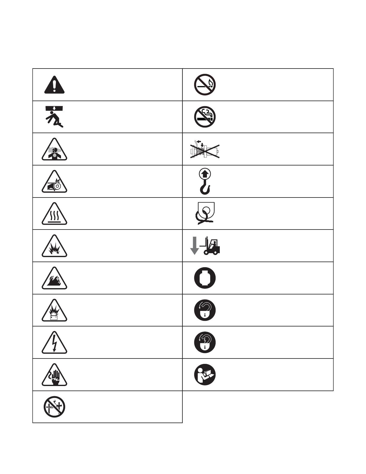
SAFETY SYMBOL SUMMARY
This equipment has been supplied with numerous safety and operating decals. These decals provide important
operating instructions and warn of dangers and hazards. Replace any missing or hard-to-read decals and use care
when washing or cleaning the unit. Decal placement and part numbers can be found in the parts manual. Below is
a summary of the intended meanings for the symbols used on the decals.
Hot surface(s). Do not touch.
No open flames.
No smoking.
Do not operate winch if cable
develops slack or is not spooling
correctly.
Read and understand the
supplied operator’s manual
before operating unit.
Explosive gases can cause
blindness or injury. Shield eyes
when servicing batteries.
Hazardous voltage. Follow lockout
tagout before servicing.
Do not operate unit near powerlines;
Contact with powerlines can cause
electrocution.
Fire hazard.
Use clean liquid propane gas
only.
Lockout/tagout - mechanical.
Secure safety pin before operating
or servicing unit.
Lockout/tagout - electical.
Secure power sources before
servicing unit.
Anchor/tie down point.
Lift here only.
Dangerous voltage may be
present.
Explosion hazard. Forklift here only.
Safety alert symbol; used to alert
you to potential personal
injury hazards.
Crush Hazard; stay clear of this
area.
00275
Belt/entanglement hazard; keep
body parts clear of this area.
Asphyxiation hazard; operate in
well ventilated area.

11
SPECIFICATIONS
MAGNUM MODEL MLT4000S
Engine
Make/Brand.................................................................................................................... Generac
Engine Model
.................................................................................................................GN-220
EPA Tier ......................................................................................................................... Phase 3
Type ............................................................................................................................... LP, 4-stroke
Operating Speed rpm.................................................................................................... 2850
Displacement in
3
(L)......................................................................................................13.18 (0.216)
Cylinders - qty ............................................................................................................... 1
Generator
Make/Brand.................................................................................................................... American Power
Model ............................................................................................................................. MAG-75INT-28H
Electrical System
Solar Panels Watts (Qty)............................................................................................... 260 (3)
Solar Panel Type............................................................................................................ Monocrystaline
Battery Type - Group Number...................................................................................... AGM-L16
Battery Voltage (Qty)..................................................................................................... 6V (8)
Battery Rating AH.......................................................................................................... 415
Lighting System
Lighting Type.................................................................................................................. LED
Lumens .......................................................................................................................... 12,000
Weights
Dry Weight - w/o Tanks lbs (kg) .................................................................................... 2607 (1183)
Dry Weight lbs (kg)........................................................................................................ 2670 (1211)
Operating Weight lbs (kg) ............................................................................................. 2720 (1234)
Fluids
Oil grade ........................................................................................................................ 5W-30
Oil capacity - w/ filter change oz (mL) ........................................................................... 24 (710)
Oil capacity - w/o filter change oz (mL) ......................................................................... 14 (414)
Fuel tank capacity lbs (kg) ............................................................................................ 7.9 (29.9)
Trailer
Number of Axles ............................................................................................................ 1
Capacity - Axle Rating lbs (kg)...................................................................................... 3000 (1360.78)
Tire Size in..................................................................................................................... 13
Hitch - Standard ............................................................................................................. 2" Ball
Maximum Tire Pressure psi........................................................................................... 65
Note: Reliable Smart mode operational temperature ranges from 15°F (-10°C) to 120°F (50°C).
Specifications are subject to change without notice.
12
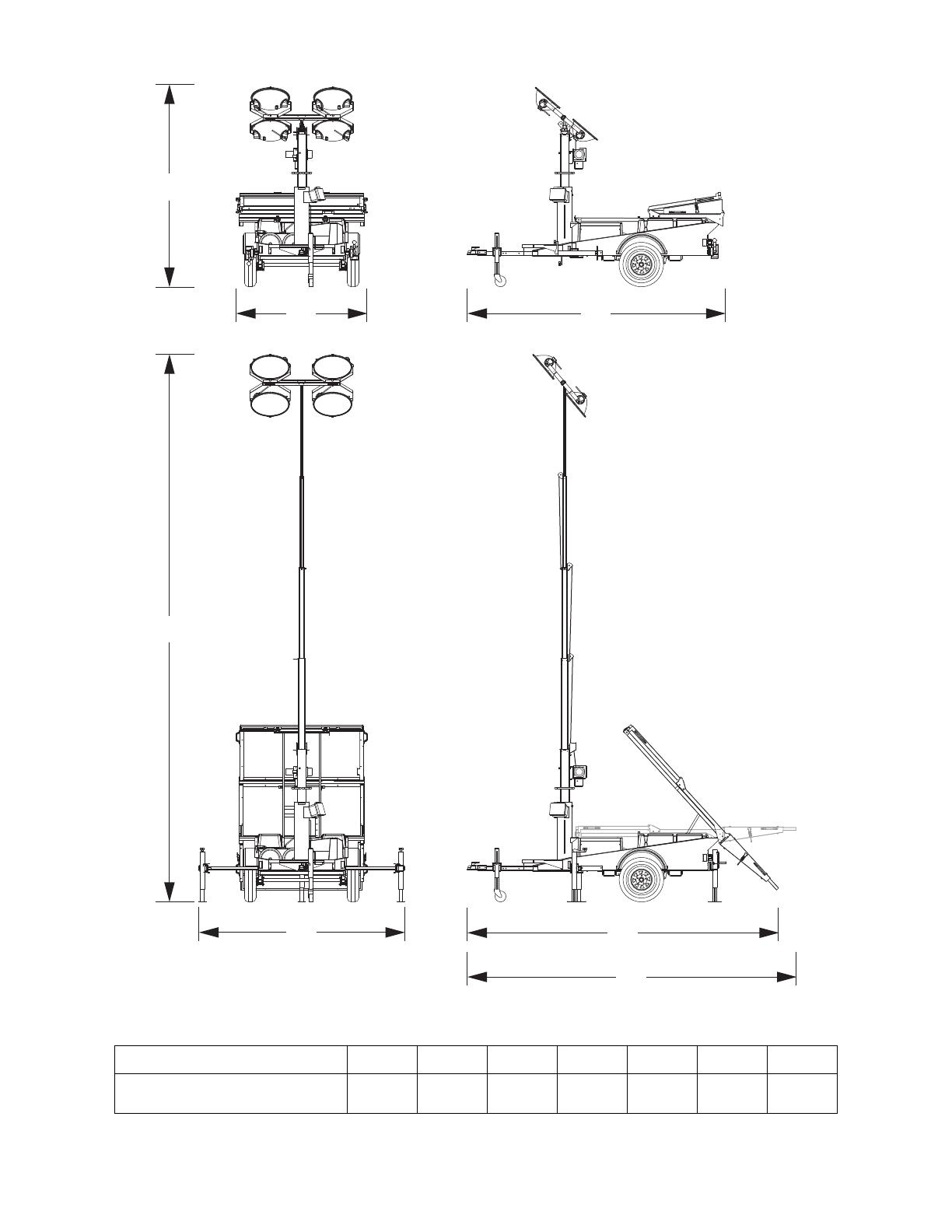
UNIT DIMENSIONS
Specifications are subject to change without notice.
Unit A B C D E F G
MLT4000S
109 in
(2.77 m)
72 in
(1.83 m)
141 in
(3.58 m)
25 ft
(7.6 m)
113 in
(2.87 m)
171 in
(4.34 m)
180 in
(4.57 m)
B
E
F
Panels at 45°
G
Panels at 0°
C
A
D
00292
13
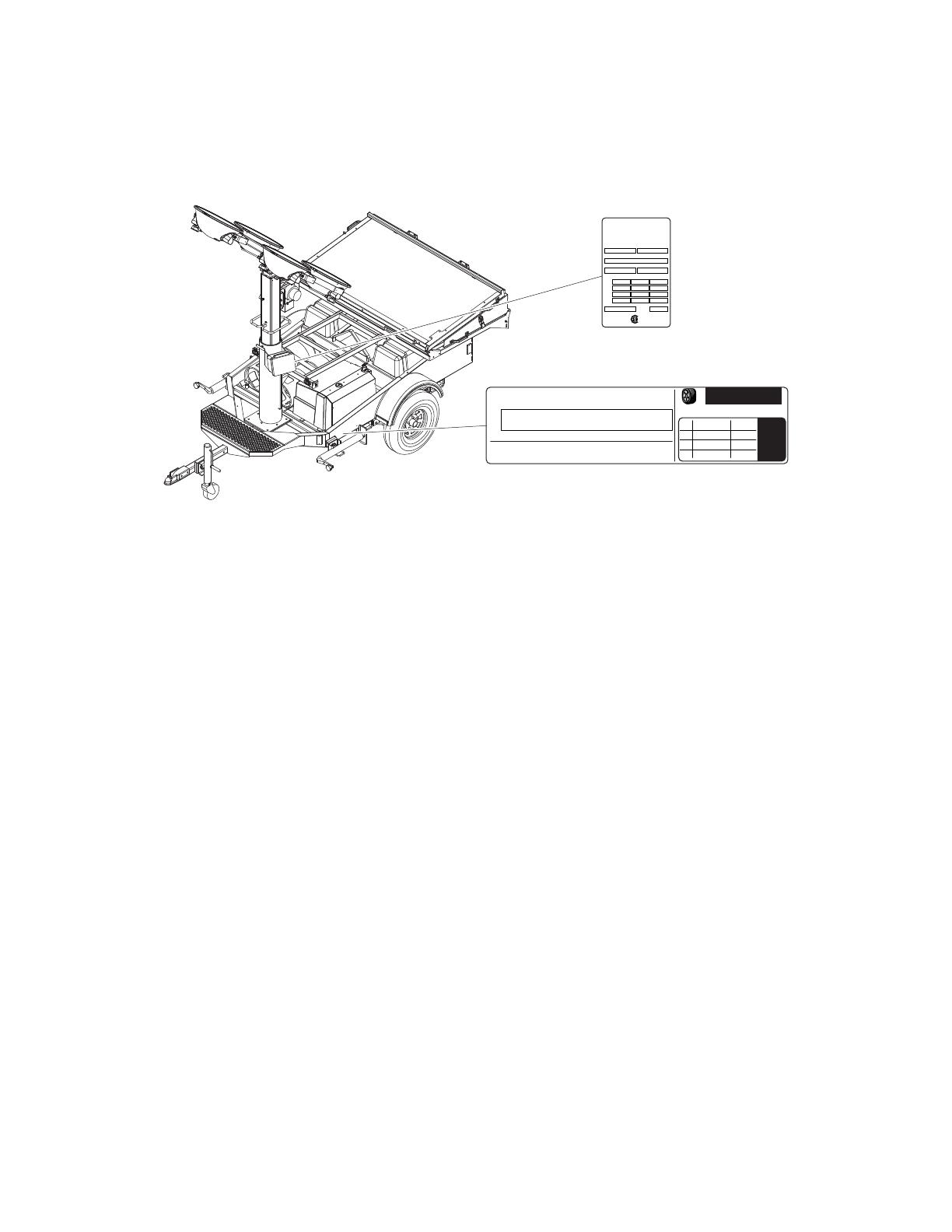
UNIT SERIAL NUMBER LOCATIONS
Refer to the illustration to locate the unit ID tag, and Vehicle Identification Number (VIN) tag on your unit. Important
information, such as the unit serial number, model number, VIN and tire loading information are found on these tags.
Record the information from these tags so it is available if the tags are lost or damaged. When ordering parts or
requesting assistance, you may be asked to provide this information.
Unit ID Tag
Located on side of control box
Serial Number
V
A
Model
KVA
FOR ELECTRICAL
EQUIPMENT ONLY.
POUR MATERIAL
ELECTRIQUE SEULEMENT.
Mfg. Code
Skidded WT (lbs/kg) rpm/freq
1 ph. 1.0PF 3 ph. .8PF 3 ph. 1.0PF
insul. class
RATING
KW
®
MAGNUM POWER PRODUCTS LLC
Manufactured by
A wholly owned subsidiary of
Generac Power Systems, Inc.
215 Power Drive • Berlin, WI 54923
1-800-926-9768
TIRE AND LOADING INFORMATION
RENSEIGNEMENTS SUR LES
PNEUS ET LE CHARGEMENT
SEE OWNER’S
MANUAL FOR
ADDITIONAL
INFORMATION
VOIR LE
MANUEL DE
L’USAGER
POUR
PLUS DE
RENSEIGNEMENTS
VIN Tag
MANUFACTURED BY/FABRIQUE PAR: Magnum Power Products LLC DATE: 00/0000
GVWR/PNBV: 000KG (0000LBS) COLD INF. PRESS./
PRESS. DE
V.I.N./N.I.V.:
00000000000000000
TYPE:
TRAILER
MODEL:
XXX000
GAWR / PNBE TIRE / PNEU RIM / JANTE GONF A FROID - KPA(PSI/LPC) SGL / DUAL
EACH
AXLE
THIS VEHICLE CONFORMS TO ALL APPLICABLE STANDARDS PRESCRIBED UNDER THE U.S. FEDERAL MOTOR VEHICLE SAFETY STANDARDS(FMVSS) AND CANADIAN
MOTOR VEHICLE SAFETY REGULATIONS IN EFFECT ON THE DATE OF MANUFACTURE.
CE VEHICULE EST CONFORME A TOUTES LES NORMES QUI LUI SONT APPLICABLES EN VERTU DU REGLEMENT SUR LA SECURITE DES VEHICULES AUTOMOBILES DU CANADA EN VIGUEUR A LA DATE SA
FABRICATION.
The weight of cargo should never exceed 0000KG (0000LBS)
Le poids du chargement ne doit jamais depasser 0000KG (0000LBS)
00265
14
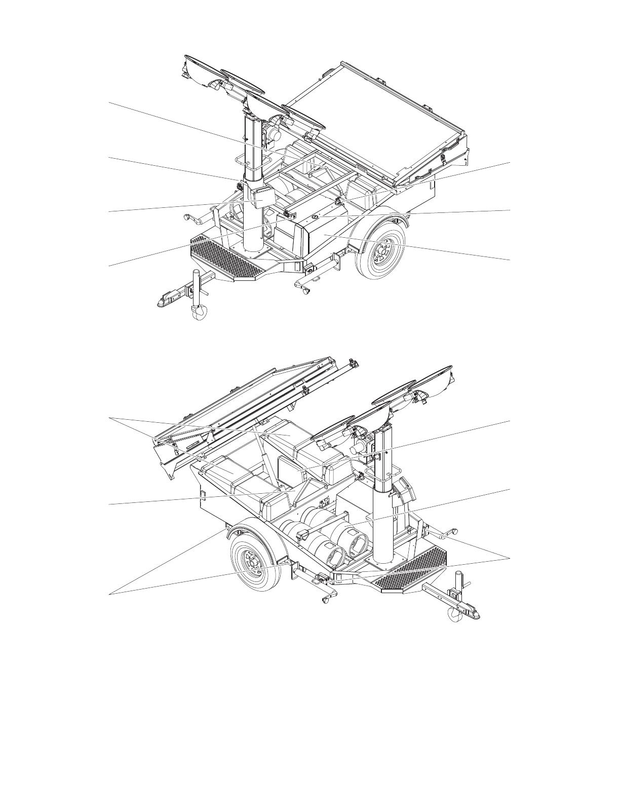
COMPONENT LOCATIONS
1
2
3
7
6
5
10
8
9
4
11
12
13
00266

15
1. Tilt Angle Indicator
2. Control Panel
3. Mast Rotation Knob
4. Central Lift Point
5. Engine Oil Dipstick
6. Engine Hour Meter
7. Engine Compartment
8. Manual Holder
9. Propane Tank Storage
10. Outriggers
11. Forklift Pockets
12. Electrical Compartment
13. Battery Compartments
16
SETUP
Setup for the MLT4000S requires preparation in order to increase the effectiveness of the solar panels. Use the
following guide to properly implement and optimize the performance of the unit.
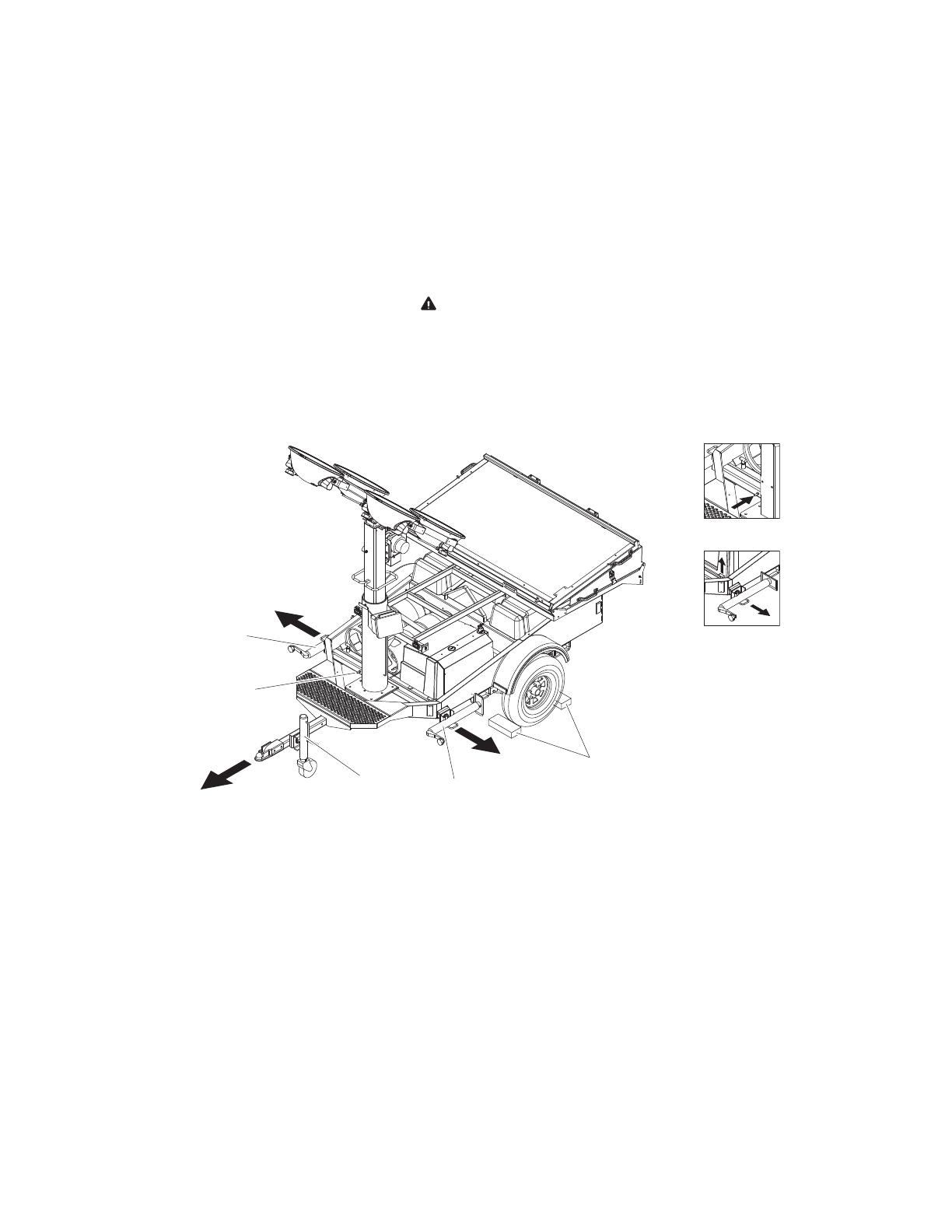
LIGHT TOWER SET UP
To set up the light tower, use the following procedure.
1. For maximum light coverage locate the tower at ground level or in a spot higher than the area being illuminated
by the lamps.
WARNING
The tower extends up to 25 ft (7.6 m). Make sure area above the trailer is open and
clear of overhead wires and obstructions.
2. Position the unit on a firm, non-combustible surface that is relatively flat, free of overhead obstructions and has
a clear southerly view. This will make it easier to level the unit and give the solar panels the greatest potential
for energy production.
3. Orient the unit with the trailer hitch facing north and block the wheels (A) on the trailer to keep it from moving.
4. Pull the locking pin on the tongue jack (B) and rotate it 90° until the pin snaps back into place. Turn the jack
handle clockwise to raise the trailer tongue off the towing vehicle.
5. If necessary, connect a good earthen ground to the grounding stud on the frame of the trailer near the trailer
tongue (C).
Note: Consult local codes for proper grounding requirements.
6. Pull the locking pin on the outriggers (D) and extend them until the pin snaps back in place. Pull the locking pin
on the outrigger jacks and rotate them 90° until the pin snaps back in place. Rotate the jack handle clockwise
to extend the jack to the ground.
7. Pull the locking pin on the rear jack and rotate it 90° until the pin snaps back into place. Turn the jack handle
clockwise to start leveling the trailer. Adjust all four jacks by turning their handles clockwise until they are firmly
in contact with the ground and the trailer is as level as possible.
North
C
D
D
B
A
DETAIL C
DETAIL D
00277

17
DEPLOYING THE SOLAR PANELS
To deploy the solar panels, use the following procedure.
1. Setup the unit as described in “Light Tower Set Up” on page 16.
2. Release the two hook clamps (A) securing the solar panels together on both sides of the unit.
3. Rotate the top/front solar panel (B) forward to the tilt frame. Secure the panel using the twist lock clamps on both
sides of the tilt frame (C).
Always support the solar panels down to their resting position completely. Allowing the solar
panels to drop or fall may damage the solar panels and/or tilt frame.
4. Rotate the bottom/rear solar panel (D) backward to the horizontal position until the rubber bumpers contact the
center panel.
5. Use the solar alignment guide described in “Solar Panel Alignment” on page 18, or the setup decal located on
the engine compartment to calculate the optimal panel angle
6. Raise the solar panels using the Panel Angle switch on the control panel (E). Press and hold the switch left or
right until the desired angle is reached. Use the Angle Indicator (F) located on the tilt frame to determine the
angle of the panels.
DETAIL E
DETAIL C
DETAIL F
DETAIL A
A
C
C
B
E
D
F
00278

18
SOLAR PANEL ALIGNMENT
This unit utilizes solar panels to charge the battery system during the day. Proper alignment of the solar panels is
crucial to the charging performance of the system. The two variables that determine the optimal alignment of the
solar panels are latitude and time of year.
The following figures provide the basic information necessary to properly align the solar panels. The alignment should
be configured upon every set up, or at least every 45 days if unit is stationary.
To determine the optimal angle for the panels, use the provided map or a Global Positioning System (GPS) to find
the latitude of the deployment location. Reference the latitude of the unit location in the table below to determine the
correct angle for the time of year.
Note: Averaging values for intermediate latitudes and time of year is acceptable.
Latitude
Optimal Solar Panel Angle
Summer Spring/Autumn Winter
25° 5 25 45
30°103045
35°153545
40°204045
45°254545
50°304545
Note: Average values for intermediate latitudes and times.
45°
50°
40°
35°
30°
25°
20°
45°
50°
40°
35°
30°
25°
20°
Location Latitude
Berlin, WI 44°
Seattle, WA 48°
Fargo, ND 47°
Boezman, MT 46°
Minneapolis, MN 45°
Augusta, ME 44°
Chicago, IL 42°
Salt Lake City, UT 41°
New York, NY 41°
Denver, CO 40°
Columbus, OH 40°
Washington D.C. 39°
St Louis, MO 39°
San Francisco, CA 38°
Tulsa, OK 36°
Memphis, TN 35°
Atlanta, GA 34°
Phoenix, AZ 33°
Mobile, AL 31°
Houston, TX 30°
Miami, FL 26°
Mexico City, Mexico 19°
Edmonton, Canada 54°
00269

19
RAISING THE MAST
To raise the mast, use the following procedure:
1. Setup and level the unit as described in “Light Tower Set Up” on page 16.
WARNING
The tower extends up to 25 ft (7.6 m). Make sure area above the trailer is open and
clear of overhead wires and obstructions.
2. Configure the light heads on the mast to the
desired orientation. Loosen the wing nuts on the
trunnion (A) and aim. Tighten hardware completely
and make sure the lamps are connected to the
junction box.
WARNING
The unit must be level with the
outriggers extended before
raising the mast. The
outriggers must remain
extended while the mast is up.
Failure to level the unit or
extend the outriggers will
severely reduce the stability
and could allow the unit to tip
and fall.
3. Check all mast cables and pulleys (B) for exces-
sive wear or damage. Make sure the cables are
properly centered in each pulley. Check the elec-
trical cord for damage.
4. Press and hold the winch control toggle switch (C)
upward to telescope the mast to the desired height.
Extend the mast cautiously, making sure that the
electrical cord is extending at the top sections of
the mast. If for any reason, the winch cable begins
to develop slack or any of the mast sections get
stuck, STOP IMMEDIATELY and contact an
authorized service center.
CAUTION
Do not extend the mast beyond
the colored mark on the lowest
telescoping mast tube (D). A limit
switch on the mast tube will
disconnect power to the electric
winch to prevent deadheading
the winch.
5. Rotate the mast by loosening the knob (E) and manually turning the mast. When it is at the correct angle, tighten
the knob (F) to secure the mast in position.
DETAIL C
D
B
A
DETAIL E
DETAIL F
STOP
DETAIL D
00279
E, F
C
20
OPERATION
The MLT4000S uses automated control systems to supply power to the lights. The generator can be operated
manually for maintenance procedures, or to power the lights when the battery charge level is insufficient.
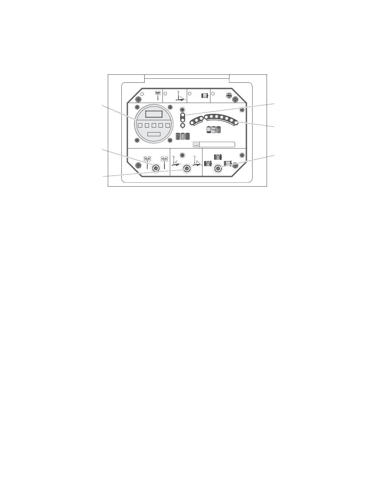
CONTROL PANEL
TIMER CONTROL: The Timer Control module is used to power the lights on demand, or using a
programmable scheduled.
BATTERY CONDITION: Three LED lights indicate the condition of the charge currently in the batteries.
• Green - Batteries have received a full charge within the last week
• Amber - Batteries have not received a full charge in more than one week.
• Red - Batteries have not received a full charge in more than two weeks.
BATTERY CHARGE LEVEL: Ten LED lights indicate the current state of charge in the batteries.
LIGHTING MODE: Toggle switch selects either a two or four light configuration [2 Lights, 4 Lights]
PANEL ANGLE: Momentary toggle switch controls the angle of the solar panels. [Down, Up]
GEN POWER: Three-position switch controls the power mode of the generator [On, Off, Smart].
GENERATOR STARTING AND OPERATION
The generator on this unit is capable of charging the battery system and powering the lights. When in Smart mode
the generator will only run if the batteries approach a critical level, charging them until the batteries have sufficient
charge. On mode will start the generator on demand, which is useful for maintenance procedures.
SMART MODE
Smart mode allows the generator to run and charge the batteries when the charge level is low. Use the following
steps to operate the unit in Smart mode:
Note: Smart mode operation may be adversely affected in ambient temperatures below 15°F (-10°C) or above 120°F
(50°C).
1. Set the Gen Power switch to the Off position.
2. Check engine oil level.
3. Check for sufficient fuel supply in the LP tanks.
TIMER CONTROL
LIGHTING MODE PANEL ANGLE GEN POWER
BATTERY STATUS
BATTERY
CONDITION
1
2 4
Set
LIGHTING
MODE
Set
PANEL
ANGLE
3
Set
GEN
POWER
Set
TIMER
CONTROL
CRITICAL
SMART
ON
OFF
DOWN
UP
42
BATTERY
CHARGE LEVEL
C
R
I
T
I
C
A
L
N
O
R
M
A
L
TO MAINTAIN BATTERY CHARGE & CONDITION,
SET GEN POWER SWITCH TO ‘SMART’ OR ‘ON’.
00270
Battery Charge Level
Battery Condition
Gen Power Switch
[On - Off - Smart]
Panel Angle Switch
[Down - Up]
Lighting Mode Switch
[2 Lights - 4 Lights]
Timer Control
/