Version 1.5 Functions
17
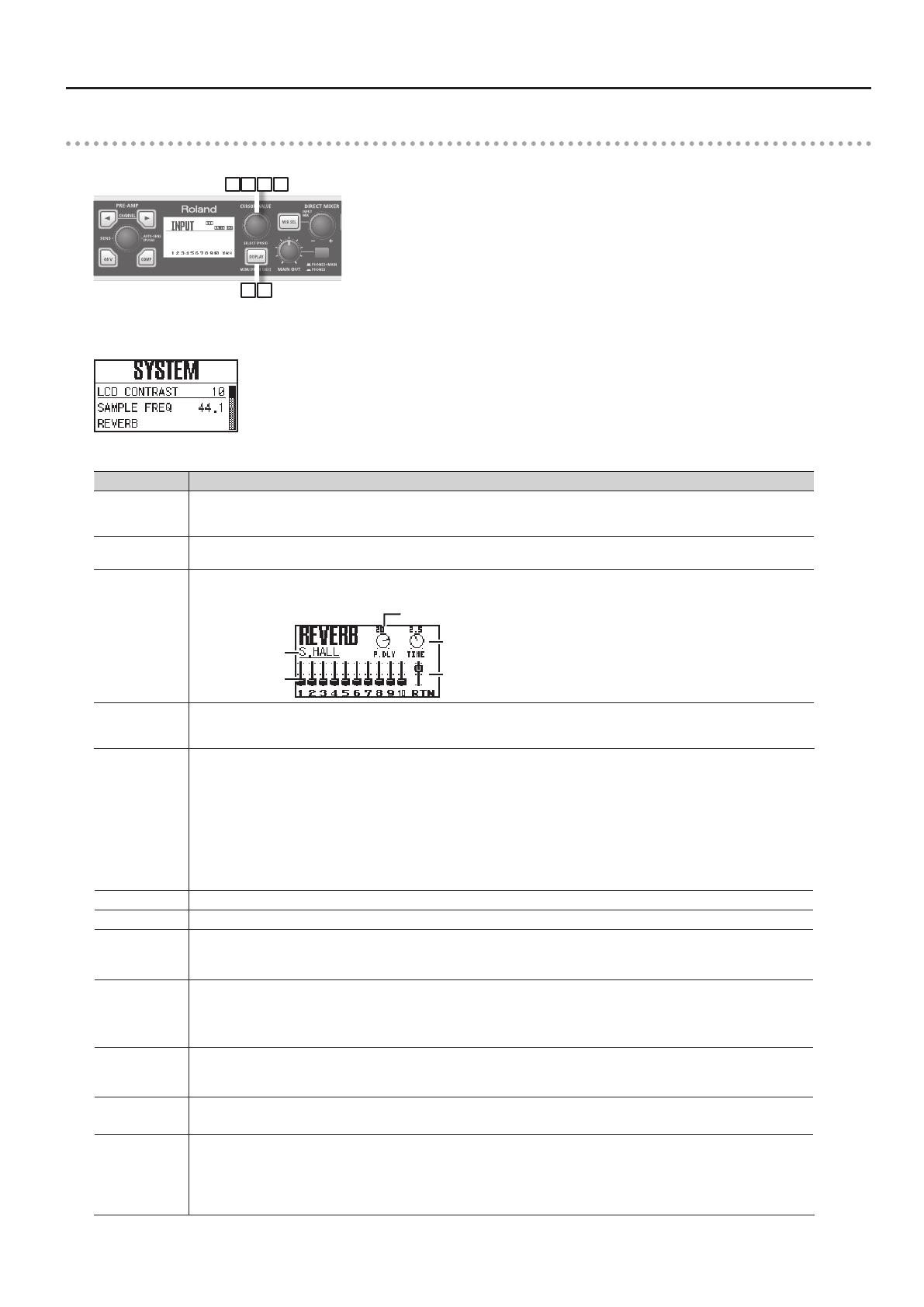
Utility section
In the utility section you can edit the OCTA-CAPTURE’s system settings.
2 43 5
1 6
1. Press and hold the [DISPLAY] button for one second.
The SYSTEM screen will appear.
2. Turn the [CURSOR/VALUE] knob to move the cursor to the parameter that you want to edit.
Screen indication Explanation
LCD CONTRAST
Adjusts the contrast of the display.
Higher values will make the display darker.
Range: 0–19
SAMPLE FREQ
Species the sampling frequency of the OCTA-CAPTURE itself.
For details, refer to “Sampling Frequency Setting” (Owner’s Manual p. 68).
REVERB
Opens the setting screen for the built-in reverb.
For details on the settings, refer to “Master A–D” (p. 22).
Reverb Return Slider
Time Knob
Reverb Type
Reverb Send
Slider
Pre-Delay Knob
PATCHBAY
For each output jack, select the source that you want to patch. As appropriate for your needs, you can freely assign the output destina-
tions of the four direct mixers and the output destinations of the playback channels from the computer.
For details on the settings, refer to “Patch Bay” (p. 11).
AUTO SENS
The recording level will be set automatically according to the maximum volume that was input during the Auto Sens setting time.
To start rehearsal, press the [AUTO-SENS] button.
Manual:
The recording level will be set automatically according to the maximum volume that was input from when you started Auto
Sens until when you pressed the [AUTO-SENS] button once again.
30sec, 1min, 3min, 5min:
If you press the [AUTO-SENS] button once again while the Auto Sens setting is in progress, the recording level will be automatically set
according to the maximum volume that was received up to that point during Auto Sens.
For details, refer to “Auto Sens setting” (owner’s Manual p. 37).
BACKUP ALL PRM. Stores the current settings (preamp, direct mixer, reverb, patch bay) in the OCTA-CAPTURE’s memory.
RECALL ALL PRM. Recalls the internally stored settings.
VS EXPAND
OFF: Choose this setting if you’re using a single OCTA-CAPTURE unit.
ON: Choose this setting if you’ve connected two OCTA-CAPTURE units. For details, refer to “Connecting Two OCTA-CAPTURE Units”
(p. 20).
DIGITAL
Turns the INPUT 9–10 (COAXIAL IN) input on/o.
AUTO: The input signal from INPUT 9–10 (COAXIAL IN) will be received. The OCTA-CAPTURE will switch to the same sampling
frequency as the incoming digital signal.
OFF: The digital signal will not be received.
CLEAR MUTE/
SOLO
Clears the mute and solo settings of the channels.
To clear the settings, choose “Yes,” and then press the [CURSOR/VALUE] knob.
If you decide not to clear the settings, choose “No,” and then press the [CURSOR/VALUE] knob.
POWER OFF
Species the time after which power to the OCTA-CAPTURE will automatically be turned o, following the last time it was operated.
Range: OFF, 4HOURS
INITIALIZE
Initializes the system settings.
For details on the values, refer to “Initializing the Settings” (p. 13).
When you select the item to be initialized, a conrmation message will appear.
To execute initialization, press the [CURSOR/VALUE] knob.
If you decide not to initialize, press the [DISPLAY] button.


