Page is loading ...

February
1988
FORM:
OM-886
Millerfi
Effective
With
Style
No.
JJ-21
MODEL
RDC-AP-1
OWNERS
MANUAL
Il~l~]:IV..~I~
Read
and
understand
the
entire
contents
of
both
this
Miller
Electric
Mfg.Co.
manual
and
the
power
source
manual
used
with
this
unit,
with
special
AMd~G,o~L~
Cor,~o~n~
emphasis
on
the
safety
material
throughout
both
manuals,
before
in-
pa.
Box
1079
stalling,
operating,
or
maintaining
this
equipment.
This
unit
and
these
instructions
are
for
use
only
by
persons
trained
and
experienced
in
the
Appleton,
WI
54912
USA
Tel.
414-734-9821
safe
operation
of
welding
equipment.
Do
not
allow
untrained
persons
to
install,
operate,
or
maintain
this
unit.
Contact
your
distributor
if
you
do
not
fully
understand
these
instructions.
PRINTED
IN
U.S.A.

LIMITED
WARRANTY
EFFECTIVE:
FEBRUARY
16,
1988
.
This
warranty
supersedes
all
previous
MILLER
warranties
and
is
exclusive
with
no
other
guarantees
or
warranties
expressed
or
implied.
LIMITED
WARRANTY
-
Subject
to
the
terms
and
condi-
In
the
case
of
Millers
breach
of
warranty
or
any
other
duty
tions
hereof,
Miller
Electric
Mfg.
Co.,
Appleton,
Wisconsin
with
respect
to
the
quality
of
any
goods,
the
exclusive
remedies
warrants
to
its
Distributor/Dealer
that
all
new
and
unused
therefore
shall
be,
at
Millers
option
(1)
repair
or
(2)
replacement
Equipment
furnished
by
Miller
is
free
from
defect
in
workman-
or,
where
authorized
in
writing
by
Miller
in
appropriate
cases,
(31
ship
and
material
as
of
the
time
and
place
of
delivery
by
Miller.
the
reasonable
cost
of
repair
or
replacement
at
an
authorized
No
warranty
is
made
by
Miller
with
respect
to
engines,
trade
Miller
service
station
or
14)
payment
of
or
credit
for
the
purchase
accessories
or
other
items
manufactured
by
others.
Such
price
(less
reasonable
depreciation
based
upon
actual
use)
upon
engines,
trade
accessories
and
other items
are
sold
subject
to
return
of
the
goods
at
Customers
risk
and
expense.
MILLERs
the
warranties
of
their
respective
manufacturers,
if
any
.
All
opton
of
repair
or
replacement
will
be
F.O.B.,
Factory,
at
S
engines
are
warranted
by
their
manufacturer
for
one
year
from
Appleton,
Wisconsin,
or
FOB.,
at
a
MILLER
authorized
service
date
of
original
purchase,
except
Tecumseh
engines
which
facility,
therefore,
no
compensation
for
transportation
costs
of
r
have
a
two
year
warranty.
any
kind
will
be
allowed.
Upon
receipt
of
notice
of
apparent
defect
or
failure,
Miller
shall
instruct
the
claimant
on
the
warranty
Except
as
specified
below,
Millers
warranty
does
not
apply
claim
procedures
to
be
followed.
to
components
having
normal
useful
life
of
less
than
one
Ii)
year,
such
as
spot
welder
tips,
relay
and
contactor
points,
MILLERMATIC
parts
that
come
in
contact
with
the
welding
ANY
EXPRESS
WARRANTY
NOT
PROVIDED
HEREIN
AND
wire
including
nozzles
and
nozzle
insulators
where
failure
does
ANY
IMPLIED
WARRANTY,
GUARANTY
OR
REPRESENTA
~
not
result
from
defect
in
workmanship
or
material.
lION
AS
TO
PERFORMANCE,
AND
ANY
REMEDY
FOR
BREACH
OF
CONTRACT
WHICH,
BUT
FOR
THIS
PROVISION,
~
Miller
shall
be
required
to
honor
warranty
claims
on
war-
MIGHT
ARISE
BY
IMPLICATION,
OPERATION
OF
LAW,
~
ranted
Equipment
in
the
event
of
failure
resulting
from
a
defect
CUSTOM
OF
TRADE
OR
COURSE
OF
DEALING,
INCLUDING
9
within
the
following
periods
from
the
date
of
delivery
of
Equip-
ANY
IMPUED
WARRANTY
OF
MERCHANTABIUTY
OR
OF
~4
mont
to
the
original
user:
FITNESS
FOR
PARTiCULAR
PURPOSE,
WiTH
RESPECT
TO
ANY
AND
ALL
EQUIPMENT
FURNISHED
BY
MILLER
IS
EX
j.~
1.
Arc
weldera.
p~r
sources,
robots,
and
components
.
1
year
CLUDED
AND
DISCLAIMED
BY
MILLER.
2.
Load
banks
1
year
~
3.
Original
main
power
rectifiers
3
years
(labor
-
1
year
only)
EXCEPT
AS
EXPRESSLY
PROVIDED
BY
MILLER
IN
V)
4.
All
welding
guns,
feeder/guns
and
torches
90
days
WRITING,
MILLER
PRODUCTS
ARE
INTENDED
FOR
4~/
5.
All
other
Millermatic
Feeders
1
year
ULTIMATE
PURCHASE
BY
COMMERCIAL!
1NDUSTRIAL
6.
Replacement
or
repair
parts,
exclusive
of
labor
..
60
days
USERS
AND
FOR
OPERATION
BY
PERSONS
TRAINED
AND
e~
7.
Batteries
6
months
EXPERIENCED
IN
THE
USE
AND
MAINTENANCE
OF
I
WELDING
EQUIPMENT
AND
NOT
FOR
CONSUMERS
OR
~~fj
provided
that
Miller
is
notified
in
writing
within
thirty
(30)
days
CONSUMER
USE.
MILLERS
WARRANTIES
DO
NOT
EXTEND
~
of
the
date
of
such
failure.
TO,
AND
NO
RESELLER
IS
AUTHORIZED
TO
EXTEND
As
a
matter
of
general
policy
only,
Miller
may
honor
claims
MILLERS
WARRANTIES
TO,
ANY
CONSUMER.
(1
submitted
by
the
onginal
user
within
the
foregoing
periods.
.-
.
-
-
.
-..
.

ERRATA
SHEET
Replace
Warranty
with
the
following:
U]
April
7,
1993
FORM:
OM-886
2..
Consumable
components:
such
as
contact
tips,
cutting
nozzles,
contactors
and
relays.
3..
Equipment
that
has
been
modified
by
any
party
other
than
MILLER,
or
equip
ment
that
has
been
improperly
installed,
improperly
operated
or
misused
based
upon
industry
standards,
or
equipment
which
has
not
had
reasonable
and
necessary
maintenance,
or
equipment
which
has
been
used
for
operation
outside
of
the
specifications
for
the
equipment.
MILLER
PRODUCTS
ARE
INTENDED
FOR
PURCHASE
AND
USE
BY
COMMER
CIALJINDUSTRIAL
USERS
AND
PERSONS
TRAINED
AND
EXPERIENCED
IN
THE
USE
AND
MAINTENANCE
OF
WELDING
EQUIPMENT.
In
the
event
of
a
warranty
claim
covered
by
this
warranty,
the
exclusive
remedies
shall
be,
at
MILLERS
option:
(I)
repair:
or
(2)
replacement;
or,
where
authorized
in
writing
by
MILLER
inappropriate
cases.
(3)
the
reasonable
cost
of
repair
or
replace
ment
at
an
authorized
MILLER
service
station;
or
(4)
payment
of
or
credit
for
the
pur
chase
price
(less
reasonable
depreciation
based
upon
actual
use)
upon
return
of
the
goods
at
customers
risk
and
expense.
MILLERS
opt
ion
of
repair
or
replacement
will
be
FOB.,
Factory
at
Appleton.
Wisconsin,
or
F.O.B.
at
a
MILLER
authorized
ser
vice
facility
as
determined
by
MILLER.
Therefore
no
compensation
or
reimburse
ment
for
transportation
Costs
of
any
kind
will
be
allowed.
TO
THE
EXTENT
PERMITTED
BY
LAW.
THE
REMEDIES
PROVIDED
HEREIN
ARE
THE
SOLE
AND
EXCLUSIVE
REMEDIES.
IN
NO
EVENT
SHALL
MILLER
BE
LIABLE
FOR
DIRECT.
INDIRECT,
SPECIAL,
INCIDENTAL
OR
CONSEQUENTIAL
DAMAGES
(INCLUDING
LOSS
OF
PROFIT),
WHETHER
BASED
ON
CON
TRACT.
TORT
OR
ANY
OTHER
LEGAL
THEORY.
ANY
EXPRESS
WARRANTY
NOT
PROVIDED
HEREIN
AND
ANY
IMPLIED
WAR
RANTY.
GUARANTY
OR
REPRESENTATION
AS
TO
PERFORMANCE,
AND
ANY
REMEDY
FOR
BREACH
OF
CONTRACT
TORT
OR
ANY
OTHER
LEGAL
THEORY
WHICH.
BUT
FOR
THIS
PROVISION,
MIGHT
ARISE
BY
IMPLICATION,
OPERATION
OF
LAW.
CUSTOM
OF
TRADE
OR
COURSE
OF
DEALING,
IN
CLUDING
ANY
IMPLIED
WARRANTY
OF
MERCHANTABILITY
OR
FITNESS
FOR
PARTICULAR
PURPOSE.
WITH
RESPECT
TO
ANY
AND
ALL
EQUIPMENT
FURNISHED
BY
MILLER
IS
EXCLUDED
AND
DISCLAIMED
BY
MILLER.
Some
states
in
the
USA.
do
not
allow
limitations
of
how
long
an
implied
warranty
lasts,
or
the
exclusion
of
incidental,
indirect,
special
or
consequential
damages,
so
the
above
limitation
or
esclusion
may
not
apply
to
you.
Thia
warranty
provides
spe
cific
legal
rights,
and
other
rights
may
be
available,
but
may
vary
from
state
to
state.
In
Canada,
legislation
in
some
provinces
provides
for
certain
additIonal
warranties
or
remedies
other
than
as
staled
herein,
and
to
the
extent
that
they
may
not
be
waived,
the
limitations
and
exclusions
set
out
above
may
not
apply.
This
Limited
Warranly
provides
specific
legal
rights,
and
other
rights
may
be
available,
but
may
vary
from
province
to
province.
After
this
manual
was
printed,
refinements
in
equipment
design
occurred.
This
sheet
lists
exceptions
to
data
appearing
later
in
this
manual.
MILLERS
TRUE
BLU
EIM
LIMITED
WARRANTY
EffectIve
January
1,
1992
(Equipment
with
a
serial
number
preface
of
KC
or
newer)
This
limited
warranty
supersedes
all
previous
MILLER
warranties
and
is
exclusive
with
no
other
guarantees
or
warranties
expressed
or
implied.
LIMITED
WARRANTY
Subject
to
the
terms
and
conditions
below.
MILLER
Electric
Accessory
Kits
Mfg.
Co..
Appleton,
Wisconsin,
warrants
to
its
original
retail
purchaser
that
new
*
Replacement
Parts
MILLER
equipment
sold
after
the
effective
date
of
this
limited
warranty
is
free
of
de
tects
in
material
and
workmanship
at
the
time
it
is
shipped
by
MILLER.
THIS
WAR-
,
PANTY
IS
EXPRESSLY
IN
LIEU
OF
ALL
OTHER
WARRANTIES.
EXPRESS
OR
MILLER
S
True
Blue
Limited
Warranty
shall
not
apply
to:
IMPLIED.
INCLUDING
THE
WARRANTIES
OF
MERCHANTABILITY
AND
FIT
NESS
1..
Items
furnished
by
MILLER.
but
manufactured
Dy
others,
Such
as
engines
or
trade
accessories.
These
items
are
covered
by
the
manufacturers
warranty,
if
any.
Within
the
warranty
periods
listed
below.
MILLER
will
repair
or
replace
any
war
ranled
parts
or
components
that
fail
due
to
such
defects
in
material
or
workmanship.
MILLER
must
be
notified
in
writing
within
thirty
(30)
days
of
such
defector
failure,
at
which
time
MILLER
will
provide
instructions
on
the
warranty
claim
procedures
to
be
followed.
MILLER
shall
honor
warranty
claims
on
warranted
equipment
listed
below
in
the
event
of
Such
S
failure
within
the
warranty
time
periods.
All
warranty
time
periods
start
on
the
date
that
the
equipment
was
delivered
to
the
original
retail
purchaser.
and
are
as
follows:
1
5
Years
Parts
3
Years
Labor
Original
main
power
rectifiers
2..
3
Years
Parts
and
Labor
Transformer/Rectifier
Power
Sources
Plasma
Arc
Cutting
Power
Sources
*
Semi-Automatic
and
Automatic
Wire
Feeders
Robots
3..
2
Years
Parts
and
Labor
Engine
Driven
Welding
Generators
(NOTE:
Engines
are
warranted
separately
by
the
engine
manufacturer.)
4..
I
Year
Parts
and
Labor
*
Motor
Driven
Guns
*
Process
Controllers
Water
Coolant
Systems
HF
Units
*
Grids
Spot
Welders
*
Load
Banks
SDX
Transformers
Running
Gear/Trailers
*
Field
Options
(NOTE:
Field
options
are
covered
under
True
BISeTM
for
the
remaining
warranty
period
of
the
product
they
are
installed
in.
or
for
a
minimum
of
one
year
whichever
is
greater
5..
6
Months
Batteries
6..
90
Days
Parts
and
Labor
*
MIG
Guns/TIG
Torches
Plasma
Cutting
Torches
*
Remote
Controls
~1
I

AMENDMENT
TO
SECTION
5
MAINTENANCE
AND
TROUBLESHOOTING
Amend
Figure
5-2.
Circuit
Diagram
For
Relay
Control
Board
PCi
ISV.
Circuit
Diagram
No.
SB-115
929-B
Figure
5-2.
Circuit
Diagram
For
Relay
Control
Board
PCi
K
U~I~L~L
CR52
BTTTTT~L
SM
P
N
G
L
N
OM-886
Page
2

0~
~11
(0
CD
01
2
(0
a
(0
2
SI
PL2
PLG2
P3
0
o
If)
II)
0
o
~i
£~:
Q_
248
RC3
0
0)
(0
C.)
PLGI
GROUND
PC
I
Wiring
Diagram
No.
SC-i
20
693-A
KEYWAY
Figure
5-3.
Wiring
Diagram


ERRATA
SHEET
Afterihis
manual
was
printed,
refinements
in
equipment
design
occurred.
This
sheet
lists
exceptions
to
data
appearing
later
in
this
manual.
Replace
Warranty
with
the
following:
U]
MILLERS
TRUE
BLUETM
LIMITED
WARRANTY
EffectIve
January
1,
1992
(Equipment
with
a
serial
number
preface
of
KC
or
newer)
This
limited
warranty
supersedes
all
previous
MILLER
warranties
and
is
exclusive
with
no
other
guarantees
or
warranties
expressed
or
implied.
LIMITED
WARRANTY
Subject
to
the
terms
and
conditions
below.
MILLER
Electric
Accessory
Kits
MIg.
Co
.
Appleton.
Wisconsin.
warrants
to
its
original
retail
purchaser
that
new
Replacement
Parts
MILLER
equipment
sold
after
the
effective
date
of
this
limited
warranty
is
free of
de
tects
in
material
arid
workmanship
at
the
time
it
is
shipped
by
MILLER.
THIS
WAR-
.
PANTY
IS
EXPRESSLY
IN
LIEU
OF
ALL
OTHER
WARRANTIES.
EXPRESS
OR
MILLERS
True
Blue
Limited
Warranty
shall
not
apply
to:
IMPLIED,
INCLUDING
THE
WARRANTIES
OF
MERCHANTABILITY
AND
FIT
NESS.
1..
Items
furnished
by
MILLER.
but
manufactured
by
others.
Such
as
engines
or
trade
accessories.
These
items
are
covered
by
the
manufacturers
warranty,
if
Within
the
warranty
periods
listed
below.
MILLER
will
repair
or
replace
any
war-
any.
ranted
parts
or
components
that
tail
due
to
such
defects
in
material
or
workmanship
MILLER
must
be
notified
in
writing
within
thirty
(30)
days
of
such
defector
failure,
at
2.
Consumable
components:
such
as
contact
tips,
cutting
nozzles,
contactors
which
time
MILLER
will
provide
instructions
on
the
warranty
claim
procedures
lobe
and
relays.
followed
3..
Equipment
that
has
bees
modified
by
any
party
other
than
MILLER.
or
equip-
MILLER
shall
honor
warranty
claims
on
warranted
equipment
listed
below
in
the
ment
that
has
been
improperly
installed,
improperly
operated
sr
misused
event
of
such
a
failure
within
the
warranty
lime
periods.
All
warranty
time
periods
based
upon
industry
standards,
or
equipment
which
has
not
had
reasonable
start
on
the
dale
that
the
equipment
was
delivered
to
the
original
retail
purchaser,
and
necessary
maintenance,
or
equipment
which
has
been
used
for
Operation
arid
are
as
follows:
outside
of
the
specifications
for
the
equipment.
1
5
Years
Parts
-
3
Years
Labor
MILLER
PRODUCTS
ARE
INTENDED
FOR
PURCHASE
AND
USE
BY
COMMER
CIAUINDUSTRIAL
USERS
AND
PERSONS
TRAINED
AND
EXPERIENCED
IN
*
Original
main
power
rectifiers
THE
USE
AND
MAINTENANCE
OF
WELDING
EQUIPMENT.
2 3
Years
Parts
and
Labor
In
the
event
of
a
warranty
claim
Covered
by
this
warranty,
the
exclusive
remedies
*
Transformer/Rectifier
Power
Sources
shall
be.
at
MILLERS
option:
(I)
repair;
or
(2)
replacement:
or,
where
authorized
in
Plasma
Arc
Cutting
Power
Sources
writing
by
MILLER
in
appropriate
cases.
(3)
the
reasonable
cost
of
repair
or
replace.
SemiAutomatic
and
Automatic
Wire
Feeders
ment
at
an
authorized
MILLER
service
station:
or
(4)
payment
of
or
credit
for
the
pur
Robots
chase
price
(less
reasonable
depreciation
based
upon
actual
use)
upon
return
of
the
goods
at
customers
risk
and
expense.
MILLERS
option
of
repair
or
replacement
3..
2
Years
Parts
and
Labor
will
be
FOB..
Factory
at
Appleton.
Wisconsin.
Or
F.O.B.
at
a
MILLER
authorized
ser
vice
facility
as
determined
by
MILLER.
Therefore
no
compensation
or
reimburse-
Engine
Driven
Welding
Generators
ment
for
transportation
costs
of
any
kind
will
be
allowed.
(NOTE:
Engines
are
warranted
separately
by
the
engine
manufacturer.)
4
t
Year
Parts
and
Labor
TO
THE
EXTENT
PERMITTED
BY
LAW.
THE
REMEDIES
PROVIDED
HEREIN
ARE THE
SOLE
AND
EXCLUSIVE
REMEDIES.
IN
NO
EVENT
SHALL
MILLER
BE
*
Motor
Driven
Guns
LIABLE
FOR
DIRECT,
INDIRECT.
SPECIAL.
INCIDENTAL
OR
CONSEQUENTIAL
*
Process
Controllers
DAMAGES
(INCLUDING
LOSS OF
PROFIT),
WHETHER
BASED
ON
CON
Water
Coolant
Systems
TRACT.
TORT
OR
ANY
OTHER
LEGAL
THEORY.
HF
Units
ANY
EXPRESS
WARRANTY
NOT
PROVIDED
HEREIN
AND
ANY
IMPLIED
WAR-
Grids
PANTY,
GUARANTY
OR
REPRESENTATION
AS
TO
PERFORMANCE.
AND
ANY
Spot
Welders
REMEDY
FOR
BREACH
OF
CONTRACT
TORT
OR
ANY
OTHER
LEGAL
Load
Banks
THEORY
WHICH.
BUT
FOR
THIS
PROVISION,
MIGHT
ARISE
BY
IMPLICATION,
SDX
Transformers
OPERATION
OF
LAW.
CUSTOM
OF
TRADE
OR
COURSE
OF
DEALING.
IN
CLUDING
ANY
IMPLIED
WARRANTY
OF
MERCHANTABILITY
OR
FITNESS
ear
rai
ers
FOR
PARTICULAR
PURPOSE,
WITH
RESPECT
TO
ANY
AND
ALL
EQUIPMENT
Field
Options
FURNISHED
BY
MILLER
IS
EXCLUDED
AND
DISCLAIMED
BY
MILLER.
(NOTE:
Field
options
are
covered
under
True
BI5CTM
for
the
remaining
warranty
period
of
the
product
they
are
installed
in.
or
for
a
minimum
of
Some
states
in
the
U.S.A.
do
not
allow
limitations
of
how
long
an
implied
warranty
one
year
whichever
is
greater.(
lasts,
or
the
exclusion
of
incidental,
indirect,
special
or
consequential
damages,
so
the
above
limitation
or
exclusion
may
not
apply
to
you.
This
warranty
provides
spa-
5..
6
Months
Batteries
citic
legal
rights,
and
other
rights
may
be
available,
but
may
vary
from
st
ale
to
stale.
6.
90
Days
Parts
and
Labor
In
Canada,
legislation
in
some
provinces
provides
for
certain
additional
warranties
*
MIG
GunsITIG
Torches
or
remedies
other
than
as
stated
herein.
and
to
the
extent
that
they
may
nsf
be
waived,
the
limitations
and
exclusions
set
out
above
may
not
apply.
This
Limited
Plasma
Cutting
Torches
Warranty
provides
specific
legal
rights,
and
other
rights
may
be
available.
but
may
*
Remote
Controls
vary
from
province
to
province.
.

AMENDMENT
TO
SECTION
5
MAINTENANCE
AND
TROUBLESHOOTING
Amend
Figure
5-2.
Circuit
Diagram
For
Relay
Control
Board
PCi
I
~V.
Figure
5-2.
Circuit
Diagram
For
Relay
Control
Board
PCi
CR~2
It~fl~
~jH–~
B
A
U
C
T
0
F
.J
S
~
P
N
6
L
H
Circuit
Diagram
No.
SB-115
929-B
OM-886
Page
2

274
1Pt3-GI
SI
PL2
PLG2
P3
0
0
If)
If)
U
U
~J
n~
a
a a
m
(0
C
CD
(71
P
(0
a
0)
(0
LI)
2
246
PC3
0
0
-D
0)
In
ID
C.)
PLGI
GROUND
PC
I
Wiring
Diagram
No.
SC-i
20
693-A
KEYWAY
Figure
5-3.
Wiring
Diagram


Section
No.
Page
No.
SECTION
1
-
INTRODUCTION
1
-
1.
General
Information
And
Safety
1
1
-
2.
Receiving-Handling
1
1
-
3.
Description
1
SECTION
2
-
INSTALLATION
2-1.
Location
2
2
-
2.
115
Volts
AC
Connections
To
Wire
Feeder
3
2
-
3.
Output
Control
Connections
3
2
-
4.
115
VAC/Contactor
Connections
To
Welding
Power
Source
3
2
-
5.
Remote
Control
Receptacle
3
SECTION
3
-
OPERATOR
CONTROLS
3
-
1.
Amperage
And
Voltage
Controls
4
3
-
2.
Digital
Display,
Display
Select
Switch,
And
Indicator
Lights
4
3
-
3.
Remote
Control
Switch
4
3
-
4.
CV/CC
Switch
4
3
-5.
Output/Contactor
Switch
4
3
-
6.
Arc
Control/Inductance
Control
4
SECTION
4
-
SEQUENCE
OF
OPERATION
4
-
1.
Gas
Metal
Arc
(GMAW)
And
Flux
Cored
Arc
Welding
(FCAW)
5
4
-
2.
Shielded
Metal
Arc
Welding
(SMAW)
6
4
-
3.
Submerged
Arc
Welding
(SAW)
6
4
-
4.
Gas
Tungsten
Arc
Welding
(GTAW)
6
4
-
5.
Air
Carbon
Arc
Cutting
And
Gouging
(AAC)
6
4
-
6.
Shutting
Down
7
SECTION
5
-
MAINTENANCE
&
TROUBLESHOOTING
5
-
1.
Inspection
And
Upkeep
7
5
-
2.
Circuit
Board
Handling
Precautions
7
5
-
3.
Troubleshooting
Chart
7

SECTION
1
-
INTRODUCTION
1
-
1.
GENERAL
INFORMATION
AND
SAFETY
A.
General
ment.
B.
Safety
WARNING
WARNING
CAUTION
Figure
1
-1.
Specifications
TB-120
603
Information
presented
in
this
manual
and
on
various
labels,
tags,
and
plates
on
the
unit
pertains
to
equip
ment
design,
installation,
operation,
maintenance,
and
troubleshooting
which
should
be
read,
understood,
and
followed
for
the
safe
and
effective
use
of
this
equip-
The
installation,
operation,
maintenance,
and
troubleshooting
of
arc
welding
equipment
requires
practices
and
procedures
which
ensure
personal
safety
and
the
safety
of
others.
Therefore,
this
equipment
is
to
be
installed,
operated,
and
maintained
only
by
qualified
persons
in
accordance
with
this
manual
and
all
ap
plicable
codes
such
as,
but
not
limited
to,
those
listed
at
the
end
of
Section
1
-
Safety
Rules
For
Operation
Of
Arc
Welding
Power
Source
in
the
welding
power
source
Owners
Manual.
Safety
instructions
specifically
pertaining
to
this
unit
ap
pear
throughout
this
manual
highlighted
by
the
signal
words
and
EW
which
identify
different
levels
of
hazard.
statements
include
installation,
operation,
and
maintenance
procedures
or
practices
which
if
not
carefully
followed
could
result
in
serious
personal
injury
or
loss
of
life.
____________
statements
include
installation,
operation,
and
maintenance
procedures
or
practices
which
if
not
carefully
followed
could
result
in
minor
personal
injury
or
damage
to
this
equipment.
A
third
signal
word,
II~I~.];If~.1~Il
highlights
instruc
tions
which
need
special
emphasis
to
obtain
the
most
efficient
operation
of
this
equipment.
1
-
2.
RECEIVING
-
HANDLING
-
Before
installing
this
equipment,
clean
all
packing
material
from
around
the
unit
and
carefully
inspect
for
any
damage
that
may
have
occurred
during
shipment.
Any
claims
for
loss
or
damage
that
may
have
occurred
in
transit
must
be
filed
by
the
purchaser
with
the
carrier.
A
copy
of
the
bill
of
lading
will
be
furnished
by
the
manufacturer
on
re
quest
if
occasion
to
file
claim
arises.
When
requesting
information
concerning
this
equip
ment,
it
is
essential
that
Model
Description
and
Style
Number
of
the
equipment
be
supplied.
1
-
3.
DESCRIPTION
-
The
RDC-AP-1
is
a
remote
control
with
digital
readout,
designed
to
control
an
ARC
PAK
welding
power
source.
The
unit
provides
the
capability
of
presetting
voltage
to
the
nearest
tenth
of
a
volt
and
current
to
the
nearest
ampere.
The
RDC-AP-1
displays
the
actual
value
of
the
selected
parameter
upon
arc
initiation.
The
RDC-AP-1
is
equipped
with
a
contactor
switch,
ARC
CONTROL
potentiometer,
and
CC/CV
switch
for
controlling
functions
of
the
welding
power
source.
The
RDC-AP-1
unit
can
be
used
to
preset
voltage
for
a
single
digital
wire
feeder
or
one
side
of
a
dual
digital
wire
feeder.
OM-886
Page
1

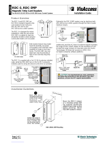
SECTION
2
-
INSTALLATION
115
VAC/Contactor
Receptacle
2
-
1.
LOCATION
-
The
RDC-AP-1
unit
is
designed
to
mount
on
top
of
the
digital
wire
feeder.
To
install
the
RDC-AP-1
unit,
proceed
as
follows:
WARNING
__________
ELECTRIC
SHOCK
can
kill.
Do
not
touch
live
electrical
parts.
Shut
down
wire
feeder
and
welding
power
source
and
disconnect
input
power
employing
lockout/tagging
procedures
before
beginning
this
installation.
Lockout/tagging
procedures
consist
of
padlocking
line
disconnect
switch
in
open
position,
removing
fuses
from
fuse
box,
or
shutting
off
and
red-tagging
circuit
breaker
or
other
disconnecting
device.
1.
Loosen
wire
feeder
wrapper
screws
(4)
that
match
the
RDC-AP-1
unit
wrapper
screw
slots.
Figure
2
-
1.
Rear
Panel
View
TA-120
551
2.
Place
RDC-AP-1
unit
on
top
of
wire feeder
with
front
panels
facing
same
direction.
3.
Slide
RDC-AP-1
unit
down
Onto
screws.
Positive
Negative
4.
Tighten
the
wire
feeder
wrapper
screws.
Feeder
115
VAC
TA-120
444
I
Output
Control
Receptacle
Feeder
115VAC
Cord
ARC
PAK
350
115
VAC/Contactor
Control
Cord
Digital
Wire
Feeder
Digital
Wire
Feeder
Figure2
-2.
RDC-AP-1
Installation
With
Wire
Feeder
OM-886
Page
2

2
-2.
115
VOLTS
AC
CONNECTIONS
TO
WIRE
FEEDER
(Figure
2-1
And
2-2)
-
Connect
the
four-
socket
plug
from
the
rear
of
the
RDC-AP-1
unit
to
the
four-pin
receptacle
on
the
rear
of
the
wire
feeder.
2
-
3.
OUTPUT
CONTROL
CONNECTIONS
(Figures
2-1,
2-2, 2-3,
And
2-4)
-
Connect
the
17-socket
plug
on
the
supplied
interconnecting
cord
to
the
17-pin
receptacle
on
the
rear
of
the
RDC-AP-1
unit.
Route
and
connect
the
remaining
end
to
the
REMOTE
CONTROL
receptacle
on
the
welding
power
source.
2
-4.
115
VAC/CONTACTOR
CONNECTIONS
TO
WELDING
POWER
SOURCE
(Figures
2-1,
2-2,2-3,
And
2-4)
-
Connect
the
four-socket
plug
on
the
115
volts/contactor
cord
(supplied
with
the
wire
feeder)
to
the
four-pin
receptacle
on
the
rear
of
the
RDC-AP-1
unit.
Connect
the
three-pole
twistlock
plug
on
the
115
volt/contactor
cord
to
the
115
volts
ac
twistlock
recep
tacle
on
the
power
source
adapter
cord.
Connect
the
two-pole
twistlock
plug
on
the
115
volt/contactor
cord
to
the
remote
contactor
control
receptacle
on
the
power
source
adapter
cord.
Connect
the
14-pin
plug
on
the
power
source
adapter
cord
to
the
14-socket
WIRE
FEED
receptacle
on
the
welding
power
source.
2
-
5.
REMOTE
CONTROL
RECEPTACLE
(Figures
2-2
And
3-1)
-
The
Remote
Control
receptacle,
located
on
the
front
of
the
RDC-AP-1
unit,
is
provided
for
con
necting
an
optional
digital
dual
schedule
control.
Con
nect
the
six-pin
plug
on
the
output
control
cord
from
the
Digital
Dual
Schedule
Control
to
the
Remote
Con
Ret.TA-120445
trol
receptacle.
When
using
a
Digital
Dual
Schedule
Control,
place
the
Remote
Control
switch
in
the
REMOTE
position.
SECTION
3
-
OPERATOR
CONTROLS
Arc
Control/
Inductance
Control
CV/CC
SwItch
Output/Contactor
Switch
Remote
Control
Switch
Remote
Control
Receptacle
Voltage
Control
TA-120
550
Figure
3
-
1.
Front
Panel
View
ARC
PAK
350
Output
Control
Cord
115VAC/Contactor
Cord
Rear
View
RDC-AP-1
Ref.
TA-120
445
Workpiece.
Figure
2
-
3.
Electrode
Positive
Connections
For
Shielded
Metal
Arc
Welding
(SMAW)
Without
Wire
Feeder
ARC
PAK
350
.Output
Control
Cord
Rear
View
11
5VAC/Contactor
Control
Cord
RDC-AP-1
Workpiece
Figure
2
-
4.
Electrode
Negative
Connections
For
Gas
Tungsten
Arc
Welding
(GTAW)
Without
Wire
Feeder
Digital
Amperage
Indicator
Light
Amperage
Control
Amperage/Voltage
Diaplay
Select
Switch
Voltage
Indicator
Light
OM-886
Page
3

3
-
1.
AMPERAGE
AND
VOLTAGE
CONTROLS
(Figure
3-1)
-
The
AMPS
and
VOLTS
controls
are
ten-
turn
potentiometers
which
provide
a
means
of
preset
ting
the
arc
amperage
and
voltage
from
the
RDC-AP-1
unit.
Turn
the
controls
clockwise
to
increase
the
set
tings,
or
counterclockwise
to
decrease
the
settings.
3
-
2.
DIGITAL
DISPLAY,
DISPLAY
SELECT
SWITCH,
AND
INDICATOR
LIGHTS
(Figure
3-1)
-
The
DISPLAY SELECT
switch
allows
voltage
to
be
preset
in
the
CV
mode,
or
amperage
to
be
preset
in
the
CC
mode,
and
also
selects
which
parameter
will
be
displayed
during
welding.
The
appropriate
indicator
light
will
turn
on
to
show
which
parameter
is
displayed
on
the
Digital
Display.
The
Digital
Display
shows
voltage
to
the
nearest
tenth
of
a
volt,
and
amperage
to
the
nearest
ampere.
3
-
3.
REMOTE
CONTROL
SWITCH
(Figure
3-1)
-
The
Remote
Control
switch
is
provided
for
selec
ting
single
scheduling
by
means
of
the
RDC-AP-1
unit,
or
dual
scheduling
by
means
of
an
optional
Digital
Dual
Schedule
Control
(DDSC)
and
dual
schedule
switch.
The
Remote
Control
switch
must
be
in
the
STANDARD
position
to
preset
the
welding
voltage
setting
at
the
RDC-AP-1
unit.
The
Remote
Control
switch
must
be
in
the
REMOTE
position
to
preset
the
welding
voltage
set
ting
from
the
DDSC,
and
to
dual
schedule
the
welding
voltage
settings.
3
-
4.
CV/CC
SWITCH
(Figure
3-1)
-
The
CV/CC
switch
provides
a
means
of
selecting
weld
output
for
the
desired
process.
The
CV
(Constant
Voltage)
posi
tion
causes
the
welding
power
source
to
provide
a
cons
tant
voltage
output
for
wire
feeding
applications
(GMAW,
FCAW,
SAW).
The
CC
(Constant
Current)
position
causes
the
welding
power
source
to
provide
a
constant
current
output
for
Shielded
Metal
Arc
(SMAW)
and
Gas
Tungsten
Arc
(GTAW)
Welding
pro
cesses.
The
CC
position
is
also
normally
used
for
the
Air
Carbon
Arc
(AAC)
cutting
and
gouging
process.
output
is
not
switched
on
or
off
by
a
physical
output
contactor;
rather,
the
output
is
controlled
by
relay
ac
tion
and
solid-state
components
on
the
circuit
board.
If
contactor
control
by
means
of
a
wire
feeder
or
remote
device
is
desired,
place
the
OUTPUT/CONTACTOR
switch
in
the
REMOTE
position.
Open-circuit
voltage
will
be
present
at
the
output
terminals
whenever
the
gun
switch
or
remote
device
is
closed.
The
OUTPUT/CONTACTOR
switch
REMOTE
position
is
normally
used
with
all
wire
feeding
processes
(GMAW,
FCAW,
SAW)
and
the
Gas
Tungsten
Arc
Welding
(GTAW)
process.
The
ON
position
is
normally
used
with
the
Shielded
Metal
Arc
Welding
(SMAW)
and
Air
Carbon
Arc
(AAC)
cutting
and
gouging
pro
cesses.
WARNING
_________
ELECTRIC
SHOCK
can
kill;
UNEX
PECTED
OUTPUT
can
cause
serious
injury.
Do
not
touch
live
electrical
parts.
Place
OUTPUT/CONTACTOR
switch
in
REMOTE
position
when
using
a
feeder
or
other
remote
device
connected
to
the
WIRE
FEED
receptacle
on
the
welding
power
source
for
contactor
con
trol.
If
the
OUTPUT/CO
NTACTOR
switch
is
in
the
ON
posi
tion
and
another
device
connected
to
the
WIRE
FEED
receptacle
is
used
for
contactor
control,
weld
output
(ocv)
will
be
present
continuously.
3
-6.
ARC
CONTROL/INDUCTANCE
CONTROL
(Figure
3-1)
-
This
control
functions
as
an
arc
control
in
the
CC
mode,
and
as
an
inductance
control
in
the
CV
mode.
IMPORTANT
___________
The
ARC
CONTROL/INDUCTANCE
control
may
by
adjusted
while
welding.
The
ARC
CON
TROL/INDUCTANCE
control
should
be
set
at
0
(zero)
for
the
Gas
Tungsten
Arc
Welding
(GTA
W)
process.
3
-
5.
OUTPUT/CONTACTOR
SWITCH
(Figure
3-1)
WARNING
__________
ELECTRIC
SHOCK
can
kill.
Do
not
touch
live
electrical
parts.
Do
not
touch
the
weld
output
terminals
when
the
con
tactor
is
energized.
Do
not
touch
electrode
holder
(or
gun
wire)
and
work
clamp
at
the
same
time.
The
OUTPUT!
CONTACTOR
switch
has
two
positions,
ON
and
REMOTE.
Place
the
switch
in
the
ON
position
to
provide
open-circuit
voltage.
Place
the
switch
in
the
REMOTE
position
to
stop
open-circuit
voltage
(ocv
goes
to
zero).
If
the
OUTPUT!
CONTACTOR
switch
is
in
the
ON
posi
tion,
open-circuit
voltage
will
be
present
at
the
output
terminals
whenever
the
welding
power
source
POWER
switch
ON
push
button
is
depressed.
IMPORTANT
____________
Although
the
term
CONTACTOR
is
used
on
the
nameplate
and
throughout
this
manual,
the
A.
Arc
Control
For
Shielded
Metal
Arc
Welding
(SMAW)
And
Air
Carbon
Arc
(AAC)
Pro
cesses
In
CC
Mode.
I
I~A
I
~
:
f..~
~
I
~
The
maximum
arc
control
amperage
available
is
100
amperes
above
the
selected
output
amperes
value.
However,
the
welding
power
source
output,
including
arc
control
amperes,
cannot
exceed
the
welding
power
source
rating.
See
welding
power
source
volt-ampere
curves
for
CC
mode
in
welding
power
source
Owners
Manual
for
graphic
presentation
of
the
arc
control
function.
The
ARC
CONTROL/INDUCTANCE
control
provides
variable
selection
of
short-circuit
amperage
to
suit
in
dividual
welding
conditions.
Rotating
this
control
clockwise
causes
the
amperage
to
increase
as
the
short-
circuit
condition
is
approached.
When
the
control
is
set
at
10,
the
short-circuit
amperage
is
considerably
higher
(up
to
100
amperes)
than
the
normal
welding
amperage
(see
welding
power
source
volt-ampere
curves
for
CC
mode
in
welding
OM-886
Page
4

power
source
Owners
Manual
and
IMPORTANT
block
at
beginning
of
this
Subsection).
This
provides
extra
amperage
for
arc
starting
in
out-of-position
welds
as
well
as
the
momentary
overcurrents
necessary
for
cer
tain
types
of
electrodes.
When
the
control
is
set
at
0,
short-circuit
amperage
is
the
same
as
the
welding
amperage.
When
the
control
is
set
at
5,
short-circuit
amperage
is
approximately
half
that
of
the
10
position,
but
still
higher
than
normal
welding
amperage.
The
5
position
provides
a
moderate
amperage
increase
for
arc
starting
necessary
for
certain
types
of
electrodes
and
applica
tions.
Select
the
setting
best
suited
for
the
application
and
type
of
electrode.
B.
Inductance
Control
For
Gas
Metal
Arc
Welding
(GMAW),
Flux
Core
Arc
Welding
(FCAW),
And
Submerged
Arc
Welding
(SAW)
In
CV
Mode.
Rotating
the
ARC
CONTROL/INDUCTANCE
control
clockwise
electronically
increases
inducance.
As
the
level
of
inductance
increases,
the
rate
of
amperage
change
or
speed
of
response
slows
down.
The
slower
response
time
produces
a
softer
arc,
more
fluid
welding
puddle,
and
flatter,
smoother
bead.
The
0
(zero)
setting
provides
minimum
inductance,
i.e.,
a
stiff,
fast-responding
arc,
and
a
small,
fast-freezing
puddle.
The
10
setting
gives
maximum
inductance
characteristics,
i.e.,
a
soft,
slow-responding,
low
spat
ter
arc,
and
high
weld
puddle
fluidity.
Select
the
setting
best
suited
for
the
application.
SECTION
4
-
SEQUENCE
OF
OPERATION
WARNING:
ELECTRIC
SHOCK
can
kill;
MOVING
PARTS
can
cause
serious
injury;
IMPROPER
AIR
FLOW
AND
EXPOSURE
TO
ENVIRONMENT
can
damage
internal
parts.
Do
not
touch
live
electrical
parts.
Keep
clear
of
pinch
points.
Keep
all
covers
and
panels
in
place
while
operating.
Warranty
is
void
if
the
wire
feeder
is
operated
with
any
portion
of
the
outer
enclosure
removed.
ARC
RAYS,
SPARKS,
AND
HOT
SURFACES
can
burn
eyes
and
skin;
NOISE
can
damage
hearing.
Wear
correct
eye,
ear,
and
body
protection.
FUMES
AND
GASES
can
seriously
harm
your
health.
Ventilate
to
keep
from
breathing
fumes
and
gases.
If
ventilation
is
inadequate,
use
approved
breathing
apparatus.
WELDING
WIRE
can
cause
puncture
wounds.
Do
not
point
gun
toward
any
part
of
the
body,
any
conductive
surface,
or
other
personnel.
HOT
METAL,
SPATTER,
AND
SLAG
can
cause
fire
and
burns.
Watch
for
f/re.
Have
a
fire
extinguisher
nearby,
and
know
how
to
use
it.
Allow
work
and
equipment
to
cool
before
handl
ing.
MAGNETIC
FIELDS
FROM
HIGH
CURRENTS
can
affect
pacemaker
operation.
Wearers
should
consult
their
doctor
before
going
near
arc
welding
operations.
See
Section
1
-
Safety
Rules
For
Operation
Of
Arc
Welding
Power
Sources
in
the
welding
power
source
Owners
Manual
for
basic
welding
safety
information.
4
-
1.
GAS
METAL
ARC
(GMAW)
AND
FLUX
CORED
ARC
WELDING
(FCAW)
I~1~i
1
~
I
I~c~
Read
and
follow
safety
information
at
beginning
of
entire
Section
4
before
proceeding.
1.
Install
and
prepare
welding
power
source
accor
ding
to
its
Owners
Manual.
OM-886Page5
2.
Install
and
connect
RDC-AP-1
unit
according
to
Section
2.
3.
Install
and
prepare
wire
feeder
according
to
its
Owners
Manual.
4.
Energize
the
welding
power
source
and
wire
feeder.
5.
Place
the
Remote
Control
switch
on
the
RDC
AP-1
unit
in
the
STANDARD
position.
6.
Place
the
CV/CC
switch
in
the
CV
position.
~
ELECTRIC
SHOCK
can
kill.
Do
not
touch
live
electrical
parts.
Disconnect
welding
cables
for
unused
process,
if
applicable.
The
positive
weld
cables
would
be
energized
while
welding.
7.
Place
the
OUTPUT/CONTACTOR
switch
in
the
REMOTE
position.
8.
Place
the
DISPLAY
SELECT
switch
in
the
VOLTS
position,
and
rotate
the
VOLTS
control
to
the
desired
position
(see
Section
3-1).
9.
Rotate
the
ARC
CONTROL/INDUCTANCE
con
trol
to
the
desired
position
(see
Section
3-6).
10.
Set
desired
wire
feed
speed
on
wire
feeder.
IMPORTANT
______________
If
an
optional
Digital
Dual
Schedule
Control
is
used,
place
the
Remote
Control
switch
in
the
REMOTE
position,
and
set
the
welding
settings
for
the
second
schedule
on
the
Dual
Schedule
Control.
11.
Turn
on
shielding
gas
supply.
12.
Begin
welding.

WARNING
WARNING:
WARNING
4
-
2.
SHIELDED
METAL
ARC
WELDING
(SMAW)
____________
Read
and
follow
safety
in
formation
at
beginning
of
entire
Section
4
before
proceeding.
1.
Install
and
prepare
welding
power
source
accor
ding
to
its
Owners
Manual.
2.
Install
and
connect
RDC-AP-1
unit
according
to
Section
2.
3.
Energize
the
welding
power
source.
4.
Place
the
Remote
Control
switch
in
the
STAN
DARD
position.
5.
Place
the
CV/CC
switch
in
the
CC
position.
6.
Place
the
OUTPUT/CONTACTOR
switch
in
the
ON
position.
7.
Place
the
DISPLAY
SELECT
switch
in
the
AMPS
position,
and
rotate
the
AMPS
control
to
the
desired
position
(see
Section
3-1).
8.
Rotate
the
ARC
CONTROL/INDUCTANCE
con
trol
to
the
desired
position
(see
Section
3-6).
9.
Begin
welding.
4
-
3.
SUBMERGED
ARC
WELDING
(SAW)
~
Read
and
follow
safety
information
at
beginning
of
entire
Section
4
before
proceeding.
1.
Install
and
prepare
welding
power
source
accor
ding
to
its
Owners
Manual.
2.
Install
and
connect
RDC-AP-1
unit
according
to
Section
2.
3.
Install
and
prepare
wire
feeder
system
according
to
its
Owners
Manual.
4.
Install
flux
system
according
to
its
Owners
Manual.
5.
Energize
the
welding
power
source
and
wire
feeder.
6.
Place
the
Remote
Control
switch
in
the
STAN
DARD
position.
7.
Place
the
CV/CC
switch
in
the
desired
position
(see
Section
3-4).
8.
Place
OUTPUT/CONTACTOR
switch
in
the
ON
position.
9.
Place
the
DISPLAY
SELECT
switch
in
the
desired
position,
and
rotate
the
AMPS
or
VOLTS
control
as
applicable
to
the
desired
position
(see
Section
3-1).
10.
Rotate
the
ARC
CONTROL/INDUCTANCE
con
trol
to
the
desired
position
(see
Section
3-6).
11.
Turn
on
flux
supply
valve
as
applicable.
12.
Begin
welding.
4
-4.
GAS
TUNGSTEN
ARC
WELDING
(GTAW)
Read
and
follow
safety
information
at
beginning
of
entire
Section
4
before
proceeding.
1.
Install
and
prepare
welding
power
source
accor
ding
to
its
Owners
Manual.
2.
Install
and
connect
RDC-AP-1
unit
according
to
Section
2.
3.
Install
and
connect
the
High-Frequency
unit
ac
cording
to
its
Owners
Manual,
if
applicable.
Scratch
start
Gas
Tungsten
Arc
Welding
(GTAW)
does
not
require
the
use
of
external
high
frequency.
4.
Energize
the
welding
power
source.
5.
Place
the
Remote
Control
switch
in
the
STAN
DARD
position.
6.
Place
the
CV/CC
switch
in
the
CC
position.
7.
Place
the
OUTPUT/CONTACTOR
switch
in
the
ON
position.
8.
Place
the
DISPLAY
SELECT
switch
in
the
AMPS
position,
and
rotate
the
AMPS
control
to
the
desired
position
(see
Section
3-1).
9.
Rotate
the
ARC
CONTROL/INDUCTANCE
con
trol
to
the
0
(zero)
position.
10.
Turn
on
the
shielding
gas
and
water
supplies
as
applicable.
11.
Begin
welding.
4
-
5.
AIR
CARBON
ARC
CUTTING
AND
GOUG
ING
(AAC)
____________
Read
and
follow
safety
information
at
beginning
of
entire
Section
4
before
proceeding.
1.
Install
and
prepare
welding
power
source
accor
ding
to
its
Owners
Manual.
2.
Install
RDC-AP-1
unit
as
instructed
in
Section
2.
3.
Connect
compressed
air
supply.
4.
Energize
the
welding
power
source.
OM-886
Page
6

5.
Place
the
Remote
Control
switch
in
the
STAN
DARD
position.
6.
Place
the
CV/CC
switch
in
the
CC
position.
7.
Place
the
OUTPUT/CONTACTOR
switch
in
the
ON
position.
8.
Place
the
DISPLAY
SELECT
switch
in
the
AMPS
position,
and
rotate
the
AMPS
control
to
the
desired
position
(see
Section
3-1).
9.
Rotate
the
ARC
CONTROL/INDUCTANCE
con
trol
to
the
desired
position
(see
Section
3-6).
10.
Turn
on
air
supply.
11.
Begin
cutting/gouging
process.
4
-
6.
SHUTflNG
DOWN
1.
Stop
welding.
2.
Shut
down
welding
power
source.
3.
Shut
down
wire
feeder,
if
applicable.
4.
Turn
off
shielding
gas,
water,
and
flux
supply
as
applicable.
L~~U~E
HIGH
CONCENTRATION
OF
SHIELDING
GAS
can
harm
health
or
kill.
Shut
off
gas
supply
when
not
in
use.
SECTION
5
-
MAINTENANCE
&
TROUBLESHOOTING
IMPORTANT
Every
six
months
inspect
the
labels
on
this
unit
for
legibility.
All
precautionary
labels
must
be
maintained
in
a
clearly
readable
state
and
replaced
when
necessary.
See
Parts
List
for
part
number
of
precautionary
labels.
5
-
1.
INSPECTION
AND
UPKEEP
-
Usage
and
shop
conditions
will
determine
the
frequency
and
type
of
maintenance.
At
minimum,
inspect
equipment
every
three
months
as
follows:
WARNING
ELECTRIC
SHOCK
can
kill.
Do
not
touch
five
electrical
parts.
Shut
down
wire
feeder
and
welding
power
source
and
disconnect
input
power
employing
lockout/tagging
procedures
before
inspecting,
maintaining,
or
servicing.
Lockout/tagging
procedures
consist
of
padlocking
line
disconnect
switch
in
open
position,
removing
fuses
from
fuse
box,
or
shutting
off
and
red-tagging
circuit
breaker
or
other
disconnecting
device.
Troubleshooting
of
internal
parts
to
be
performed
only
by
qualified
persons.
1.
Inspect
all
interconnecting
cords
for
damage
to
or
breaks
in
the
insulation
jacket,
particularly
at
the
plugs
and
where
the
cords
enter
the
unit.
Repair
or
replace
the
cord(s)
as
necessary.
2.
Remove
grease
and
grime
from
components,
moisture
from
electrical
parts
and
cable.
5
-
2.
CIRCUIT
BOARD
HANDLING
PRECAU
TIONS
WARNING
__________
ELECTRIC
SHOCK
can
kill.
Do
not
touch
five
electrical
parts.
Shut
down
wire
feeder
and
welding
power
source
and
disconnect
input
power
employing
lockout/tagging
procedures
before
inspecting,
maintaining,
or
servicing.
Lockout/tagging
procedures
consist
of
padlocking
line
disconnect
switch
in
open
position,
removing
fuses
from
fuse
box,
or
shutting
off
and
red-tagging
circuit
breaker
or
other
disconnecting
device.
CAUTION
_________
ELECTROSTATIC
DISCHARGE
(ESD)
can
damage
circuit
board
components.
Put
on
properly
grounded
wrist
strap
BEFORE
handling
circuit
boards.
Transport
all
static-sensitive
components
in
pro
per
static-shielding
carriers
or
packages.
Perform
work
only
at
a
static-safe
work
area.
INCORRECT
INSTALLATION
or
misaligned
plugs
can
damage
circuit
board.
Be
sure
that
plugs
are
properly
installed
and
align
ed
before
reinstalling
wrapper.
EXCESSIVE
PRESSURE
can
break
circuit
board.
Use
only
minimal
pressure
and
gentle
movement
when
disconnecting
or
connecting
board
plugs
and
removing
or
instalbng
board.
It
is
assumed
that
the
unit
was
properly
installed
accor
ding
to
Section
2
of
this
manual,
the
operator
is
familiar
with
the
function
of
controls,
the
unit
was
working
pro
perly,
and
that
the
trouble
is
not
related
to
the
welding
process.
I
I
5
-
3.
TROUBLESHOOTING
CHART
WARNING
__________
ELECTRIC
SHOCK
can
kill.
Do
not
touch
live
electrical
parts.
Shut
down
wire
feeder
and
welding
power
source
and
disconnect
input
power
employing
lockout/tagging
procedures
before
inspecting,
maintaining,
or
servicing.
Lockout/tagging
procedures
consist
of
padlocking
line
disconnect
switch
in
open
position,
removing
fuses
from
fuse
box,
or
shutting
off
and
red-tagging
circuit
breaker
or
other
disconnecting
device.
Troubleshooting
to
be
performed
only
by
qualified
per
sons.
OM-886
Page
7

IMPORTANT
Be
sure
that
all
connections
at
the
RDC-AP-
1
unit,
welding
power
source,
and
wire
feeder
are
secure
and
that
all
switches
are
in
the
proper
posi
tion
for
the
welding
application
before
proceeding
with
troubleshooting.
The
following
chart
is
designed
to
diagnose
and
provide
remedies
for
some
of
the
troubles
that
may
develop
in
this
unit.
Use
this
chart
in
conjunction
with
the
Circuit
diagram
while
performing
troubleshooting
procedures.
If
the
trouble
is
not
remedied
after
performing
these
pro
cedures,
the
nearest
Factory
Authorized
Service
Sta
tion
should
be
contacted.
In
all
cases
of
equipment
malfunction,
the
manufacturers
recommendations
should
be
strictly
followed.
TROUBLE
PROBABLE
CAUSE
REMEDY
No
Display.
,
Wire
feeder
Power
switch
in
OFF
position.
Energize
wire
feeder.
Digital
meter.
Replace
meter.
Relay
Control
Board
PCi.
Replace
PCi
(see
Section
5-2).
Unable
to
preset
either
voltage
or
amperage.
~
~
Remote
Control
switch
on
RDC-AP-1
in
REMOTE
position
without
a
Digital
Dual
Schedule
Control
con
nected.
Place
Remote
Control
switch
in
STANDARD
posi
tion
or
connect
a
Digital
Dual
Schedule
Control
(see
Section
2-5).
Relay
CR51.
Replace
CR51.
Relay
Control
Board
PCi.
Replace
PCi
(see
Section
5-2).
Unable
to
preset
voltage;
amperage
adjustment
available.
VOLTS
control
Ri.
Replace
Ri.
DISPLAY
SELECT
switch
S2.
Replace
S2.
Relay
CR52.
Replace
CR52.
Relay
Control
Board
PCi.
Replace
PCi
(see
Section
5-2).
Unable
to
preset
amperage;
voltage
adjustment
available.
AMPS
control
R2.
Replace
R2.
DISPLAY
SELECT
switch
S2.
Replace
S2.
Relay
CR52.
Replace
CR52.
Relay
Control
Board
PCi.
Replace
PCi
(see
Section
5-2).
Does
not
display
actual
parameters
while
welding.
115
VAC
connection
to
feeder.
Check
connection.
Relays
CR50
or
CR54.
Replace
relay(s).
OM-886
Page
8

3
4
PC3
E
~
F
AC
IN
2
Circuit
Diagram
No.
B-115
928-A
Figure
5
-
2.
Circuit
Diagram
For
Relay
Control
Board
PCi
/
/
I
I
2
TEl
C
0
Figure
5
-
1.
Circuit
Diagram
For
RDC-AP-1
~nm~
i-ri
E
S
A
U
C
T
D
F
J
A
SN
P
N
6
L
4
Circuit
Diagram
No.
B-115
929-A
OM-886
Page
9
/