Page is loading ...

ASSEMBLY MANUAL
Xceed
™
™

Congratulations on your commitment to tness and your purchase of the Bowex Xceed™ home
gym. Before assembling your Bowex Xceed™ home gym please read the Assembly Manual and follow the
Important Safety Precautions. For information on how to use your Bowex Xceed™ home gym refer to the
Bowex Xceed™ Owner’s Manual.
Important Safety Instructions - Assembly 1
Before Assembly 2
Parts 3
Hardware 5
Assembly 6
Table of Contents / Registration
To validate warranty support, keep the original proof of purchase and record the following information:
Serial Number __________________________
Date of Purchase __________________________
If purchased in US/Canada: To register your product warranty, go to: www.bowex.com/register or call 1 (800) 605–3369.
If purchased outside US/Canada: To register your product warranty, contact your local distributor.
For details regarding product warranty or if you have questions or problems with your product, please contact your local Bowex
distributor. To nd your local distributor, go to: www.nautilusinternational.com
Nautilus, Inc., 5415 Centerpoint Parkway, Groveport, OH 43125 USA, www.NautilusInc.com - Customer Service: North America (800) 605-3369,
[email protected] | outside U.S. or Canada: www.nautilusinternational.com | Printed in China | © 2018 Nautilus, Inc. | ® indicates trademarks
registered in the United States. These marks may be registered in other nations or otherwise protected by common law. Bowex, the Bowex logo,
Bowex Xceed, Power Rod, Nautilus, Schwinn, and Universal are trademarks owned by or licensed to Nautilus, Inc.
ORIGINAL MANUAL - ENGLISH VERSION ONLY

Assembly Manual
1
Important Safety Instructions / Before Assembly
This icon means a potentially hazardous situation which, if not avoided, could result in death or serious injury.
Obey the following warnings:
Read and understand all Warnings on this machine.
Carefully read and understand the Assembly Manual.
• Keep bystanders and children away from the product you are assembling at all times.
• Do not assemble this machine outdoors or in a wet or moist location.
• Make sure assembly is done in an appropriate work space away from foot traffic and exposure to bystanders.
• Some components of the machine can be heavy or awkward. Use a second person when doing the assembly steps involving these parts. Do not
do steps that involve heavy lifting or awkward movements on your own.
• Set up this machine on a solid, level, horizontal surface.
• Do not try to change the design or functionality of this machine. This could compromise the safety and can void the warranty.
• If replacement parts are necessary use only genuine Nautilus replacement parts and hardware. Failure to use genuine replacement parts can
cause a risk to users, keep the machine from operating correctly or void the warranty.
• Do not use the machine until it has been fully assembled and inspected for correct performance in accordance with the Owner’s Manual.
• Read and understand the complete Owner’s Manual supplied with this machine before first use. Keep the Owner’s and Assembly Manuals for
future reference.
• Do all assembly steps in the sequence given. Incorrect assembly can lead to injury.
• SAVE THESE INSTRUCTIONS.

Assembly Manual
2
Before Assembly
Please take the time to read all assembly instructions before attempting to assemble your Bowflex Xceed™ home gym. Select
where you are going to locate your machine carefully. The best place for your Bowflex Xceed™ home gym is on a hard, level
surface.
Select a workout area that provides a minimum clearance behind the rod box of 0.5 ft (15 cm) and a total width of 6.5 ft (2.0 m).
Allow a minimum of 3.0 ft (0.9 m) free space in front of the machine.
Basic Assembly Principles
Here are a few basic tips that will make your assembly of the Bowflex Xceed™ home gym quick and easy. By using these
principles, you can simplify each process and save yourself extra time and effort.
1. To make the assembly process go faster, gather the pieces you need for each step and thoroughly read the assembly
instructions for that step prior to starting assembly for the step.
2. When tightening a locknut on a bolt, use a combination wrench to grip the locknut and ensure that it is fastened securely.
3. When attaching two pieces, gently lift and look through the bolt holes to help guide the bolt through the holes.
4. As a general rule, and for all bolts and nuts on your Bowflex Xceed™ home gym, turn bolts or nuts toward the right
(clockwise) to tighten and left (counterclockwise) to loosen.
IMPORTANT: LEAVE ALL CABLES WRAPPED AND COILED UNTIL INSTRUCTED.

Assembly Manual
3
23
40
41
15
12
17
30
27
22
19
16
16
16
16
24
28
26
15
42
24
28
15
7
18
27
16
16
2
16
4
3
1
1
1
1
16
5
20
22
29
8
33
11
10
9
13
14
25
21
44
43
47
46
31
27
34
23
23
16
45
35
36
37
37
36
35
39
38
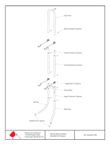
Parts / Tools

Assembly Manual
4
Item Qty Description Item Qty Description
1 4 FOOT, END CAP, FRAME 25 3 PHILLIPS SCREW 10-24X1
2 1 BASE FRAME
3 1 RIGHT FRAME RAIL (Cable Pulley Slider and Cable
are included with frame rail pulley)
26 2 THREADED STUD 1/2 X 9 1/2 BLK
4 1 LEFT FRAME RAIL (Cable Pulley Slider and Cable
are included with frame rail pulley)
27 5 LOCK NUT 3/8 G2
5 1 REAR CROSSMEMBER 28 4 LOCK NUT 1/2 G2
6 1 ABDOMINAL BRACKET 29 1 LOCK KNOB
7 1 LAT CROSS BAR W/ PULLEYS (One cable is
wrapped in each pulley bundle)
30 2 BUTTON HEAD CAP SCREW
3/8 X1
8 1 UPPER LAT TOWER 31 2 BUTTON HEAD CAP SCREW
3/8 X 2 3/4 G2-BlkO
9 1 RIGHT PULLEY ARM 32 Not used
10 1 LEFT PULLEY ARM 33 1 BRKT, AB CRUNCH
11 1 LOWER LAT TOWER FRAME 34 1 XTREME SE AB BRKT TUBE ASSY
12 1 SQUAT PULLEY FRAME 35 2 CHROME TUBE, FOAM ROLLER
13 1 SEAT BACKBONE 36 4 FOAM ROLLER
14 1 SEAT SUPPORT RAIL 37 4 END CAP, 3/4 INCH
15 4 PULLEY SLIDER 38 1 PIN, LEG EXT
16 20 BUTTON HEAD CAP SCREW
3/8 X 3/4 G2
39 1 LEG EXTENSION BACKBONE ASSEMBLY
17 1 BUTTON HEAD CAP SCREW
3/8 X 5 G2
40 1 XTREME SE SEAT ASSEMBLY
18 2 BUTTON HEAD CAP SCREW
3/8 X 3 G2
41 1 XTREME SE SEAT BACK ASSEMBLY
19 2 BUTTON HEAD CAP SCREW
5/16 X 2 1/2 G2
42 1 BOWFLEX ROD PACK 210#
20 4 BUTTON HEAD CAP SCREW
5/16 X 3/4 G2
43 1 BAR 50” BENT LAT BAR
21 3 FLAT WASHER 1/4 44 1 BAR 48” LONG WITH FOAM GRIPS
22 6 FLAT WASHER 5/16 45 1 ACC BAG LEG #1 ASSEMBLY
23 32 FLAT WASHER 3/8 46 1 PVC HANDGRIP PAIR ASSEMBLY
24 4 FLAT WASHER 1/2 47 1 AB CRUNCH STRAP ASSEMBLY
Tools
Included Not included
3/16”
7/32”
NOTE: Specifications Subject to Change Without Notice
• 7/16” Combination Wrench
• 9/16” Combination Wrench
• Adjustable Wrench
• Socket Wrench Set
• Phillips Screw Driver
• Flat Blade Screw
Driver
• Rubber Mallet
• Utility Knife
• Scissors

Assembly Manual
5
Button Head Screws:
Flat Washers:
Nylock Nuts:
Qty:2
(5/16
" x 2 1/2")
Qty: 2
(3/8" x 3")
Qty: 2
(3/8" x 1")
Qty: 4
(5/16
" x 3/4")
Qty: 20
(3/8
" x 3/4")
Qty: 2 Threaded Studs
(1/2" x 9 1/2")
Qty: 1
(3/8
" x 5")
Qty: 4
(1/2
")
Qty: 5
(3/8
")
Qty: 3
Self Threading Screws (#10 x 1
")
Qty: 32
(3/8
")
Qty: 6
(5/16
")
Qty: 3
(1/4
")
Qty: 4
(1/2
")
(NOTE: Drawings not to scale.)
Self Threading Screw:
Qty: 2
(3/8
" x 2 3/4")
Hardware

Assembly Manual
6
Step 1. Base Frame Assembly
Parts:
• Base Frame • Right Frame Rail
• Left Frame Rail • Rear Cross Member
Hardware:
• 6 Button Head Screws ( 3/8" X 3/4")
• 6 Flat Washers (3/8")
Tool: 7/32" Allen Wrench
(or Hex Wrench)
1-1
Lay all parts on floor as
shown.
1-2 Insert Frame Rail
connectors into the
Base Frame and
Rear Cross Member.
Secure with screws
and washers as shown.
Finger tighten screws
at this time.
2. Lower Lat Tower Assembly
Parts:
• Lower Lat Tower Frame
• Rod Box with Power Rod™ Pack
Hardware:
• 3 Self Threading Screws (#10 X 1")
• 3 Flat Washers (1/4")
Tool: Phillips Screw Driver
2-1
Lay parts on floor as shown. Firmly
slide Rod Box into Lower Lat Tower
Frame.
2-2 Fasten the Rod Box to the
Lower Lat Tower Frame with
screws and washers as shown.
Tighten screws until snug.
Self Threading
Screws
Flat Washers
Rod Box w/ Rods
Lower Lat Tower Frame
Rear Cross
Member
Right Frame Rail
Button Head
Screws
Flat
Washers
Flat Washers
Base Frame
Button Head Screws
Left Frame Rail
Button Head Screws
Flat Washers
Assembly

Assembly Manual
7
3. Install Lower Lat Tower Assembly
Parts:
• Lower Lat Tower Assembly
• Base Frame Assembly
Hardware:
• 2 Button Head Screws (3/8" X 3/4")
• 2 Flat Washers (3/8")
Tool: 7/32” Hex Wrench
3-1 Align the Lower Lat Tower Assembly over
the Base Frame. Push the bottom of the Lower Lat
Tower onto the connector of the Rear Cross Member
as shown.
3-2 Secure Lower Lat Tower Assembly
using screws and washers as shown.
Finger tighten screws at this time.
4. Install Seat Support Rail
Parts:
• Seat Support Rail
• Base Frame Assembly
Hardware:
• 2 Button Head Screws (3/8" X 3/4")
• 2 Flat Washers (3/8")
Tool: 7/32" Hex Wrench
4-1
Slide the bottom of the Seat Support Rail onto
the Base Frame connector as shown.
4-2 Slide the top of the Seat Support Rail onto
the Lower Lat Tower Assembly connector as
shown. Secure using screws and washers
as shown.
Finger tighten screws at this time.
Base Frame Assembly
Button
Head
Screw
Flat Washer
Button
Head
Screw
Flat
Washer
Base Frame/
Lower Lat Tower
Assembly
Seat Support Rail
Flat
Washer
Button
Head
Screw
Button
Head
Screw
Flat
Washer
Lower Lat Tower
Assembly

Assembly Manual
8
6. Install Pulley
Arms
Parts:
• Right Pulley Arm
• Left Pulley Arm
• Main Assembly
Hardware:
• 4 Washers (3/8")
• 4 Button Head Screws
(3/8" X 3/4")
Tools: 7/32" Hex Wrench
6-1
Slide Left and Right Pulley Arms onto the
connectors on the base frame as shown.
6-2 Secure Pulley Arms to Base Frame using screws
and washers as shown.
Finger tighten screws
at this time.
5. Install Squat Pulley Frame
Parts:
• Squat Pulley Frame Assembly
• Main Assembly
Hardware:
• 1 Button Head Screw (3/8" X 5")
• 1 Nylock Nut (3/8")
• 2 Button Head Screws (3/8" X 1")
• 4 Washers (3/8")
Tools: 7/32" Hex Wrench & Adjustable
or Socket Wrench
5-1
Place the Squat Pulley Frame behind the Seat
Support Rail and align the top screw holes.
Secure using a 3/8" X 5" screw, washer and nut in
the top hole as shown.
5-2 Install screws and washers into the bottom holes
of the Squat Pulley Frame as shown.
Button
Head
Screw
Flat
Washers
Nylock Nut
Squat Pulley
Frame
Flat
Washers
Button Head
Screws
Squat pulley frame not shown for clarity.
Squat pulley frame not shown for clarity.
Base Frame &
Lower Lat Tower
Assembly
Flat Washers
Button Head
Screw
Button
Head Screw
Right Pulley Arm
Left Pulley Arm
Button Head
Screws
Washers

Assembly Manual
9
8. Install Slider Pulleys
Parts:
• 2 Slider Pulleys with Cable Assembly
• Main Assembly
Tools: 3/16” Hex Wrench
8-1
Install a Slider Pulley onto each Pulley Arm as
shown.
8-2 Choose any of the four holes to secure.
Slider Pulley w/ Cable
Assembly
Slider Pulley w/ Cable
Assembly
7. Secure Pulley Arms
Hardware:
• 2 Threaded Studs (1/2" X 9 1/2")
• 4 Nylock Nuts (1/2")
• 4 Washers (1/2")
Tool: Rubber Mallet
7-1
Align the two holes in the Pulley
Arms with those in the Lower Lat
Tower Assembly and secure using
threaded studs, washers and nuts
as shown.
Flat Washers
Threaded
Studs
Nylock Nuts
Nylock Nuts
Flat Washers

Assembly Manual
10
10. Leg Extension Assembly
Parts:
• Leg Extension Backbone
• 2 Chrome Tubes
• 4 Foam Rollers
• 4 End Caps
Tool: Rubber Mallet
10 -1
Insert Chrome Tubes through the upper hole
and one of the lower holes in the Leg Extension.
(Select hole for your comfort level.)
10-2 Slide Foam Rollers onto the Chrome Tubes and
secure with end caps. A rubber mallet may be
needed to secure the end caps.
Note: The Leg Extension may be adjusted
during workout to best suit your height
and personal preferences.
9. Seat Assembly
Parts:
• Seat Backbone
• Seat Bottom
Hardware:
• 4 Button Head Screws (5/16" X 3/4")
• 4 Washers (5/16")
Tool: 3/16" Hex Wrench
9-1
Install the Seat Backbone to the
underside of the Seat Pad using screws
and washers as shown.
Button Head
Screws
Flat Washers
Seat Backbone
Seat Bottom
Leg Extension
Backbone
End Caps
Foam Rollers
Chrome Tubes
Leg Extension
Pin

Assembly Manual
11
11. Install Leg Extension Assembly
Parts:
• Leg Extension Assembly
• Lock Knob
11-1
Insert Leg Extension Backbone into open
end of Seat Backbone as shown.
11-2 Align one hole of the Leg Extension with
the hole in the Seat Backbone to fit your
height and secure with the Lock Knob as
shown.
Lock Knob
12. Install Seat Assembly
Parts:
• Seat Assembly
• Main Assembly
12-1 Align the top two hooks on the Seat
Backbone with one of the lower
pairs of pins on the Seat Support
Rail.
12-2 Tip seat front up and slide
hooks onto pins. Rotate seat down
and back to use.
Note: Use lower pins until the seat back
is installed. Reverse procedure to
remove seat.
Seat
Backbone
Leg
Extension
Backbone
Seat
Backbone
Seat Support
Rail

Assembly Manual
12
14. Upper Lat Tower Assembly
Parts:
• Upper Lat Tower
• Lat Cross Bar
Hardware:
• 2 Button Head Screws (3/8" X 3")
• 4 Washers (3/8")
• 2 Nylock Nuts (3/8”)
Tool: 7/32" Hex Wrench and Adjustable Wrench
14-1 Align the two holes on the Lat Cross Bar with those
on the Upper Lat Tower as shown.
14-2 Secure using washers and screws as shown.
13. Install Seat Back Pad
Note: The back of the Seat Back Pad
has two pairs of holes. Select the
appropriate
set based on your height.
Parts:
• Seat Back Pad
• Main Assembly
Hardware:
• 2 Button Head Screws (5/16" X 2 1/2")
• 2 Washers (5/16")
Tool: 3/16" Hex Wrench
13-1 Position Seat Back Pad against the
Seat Support Rail and align the
screw holes for your height with
those on the Seat Support Rail.
13-2 Secure Seat Back Pad to the Seat Support Rail using screws
and washers as shown.
Button Head
Screws
Flat Washers
Lat Cross Bar
Upper Lat Tower

Assembly Manual
13
15 . Ab Bracket Assembly
Parts:
• Abdominal Bracket (2 pieces)
Hardware:
• 2 Button Head Screws (3/8" X 2 3/4")
• 4 Washers (3/8")
• 2 Lock Nuts (3/8”)
Tool: 7/32" Hex Wrench
15-1 Attach the Ab Lat Cross Bar to the Ab Bracket as shown.
Ab Bracket
Ab Lat Cross Bar
Flat Washer
Lock Nut
Flat Washer
Button Head Cap Screw

Assembly Manual
14
16. Install Upper Lat Tower Assembly and Ab Bracket
Parts:
• Upper Lat Tower Assembly
• Abdominal Bracket
• Main Assembly
Hardware:
• 6 Button Head Screws (3/8" X 3/4")
• 6 Washers (3/8")
Tool: 7/32" Hex Wrench
16 -1 Slide the Upper Lat Tower Assembly onto the
Lower Lat Tower.
16-2 Place the Ab Bracket against the Lat Tower and secure the entire
assembly with 6 washers and screws as shown.
Ab Bracket on Lat
Tower

Assembly Manual
15
Chest Exercises
Leg and Squat Exercises
Abdominal Exercises
Lat Pulldown Exercises
17. Tighten Hardware
17-1 Carefully go over the entire Bowflex Xceed™ home gym and tighten all
hardware before proceeding to the next step. Pay close attention to the
hardware installed in Steps 1, 3, 4, and 6.
18. Connecting Cables
Parts:
Completed Bowflex Xceed™ home gym
Tool: Scissors or other cutting tool (not included)
18 -1
Remove the wrapping from around the coiled cable and pulley
attached to the Right and Left Frame Rails.
18-2 Remove the wrapping from around the coiled cable and pulley
attached to the left and right side of the lat tower.
18-3 Attach the cable to the home gym following the routing for the
various exercise positions.
Note: As you use your home gym, you will connect the cables and
pulleys in a variety of ways to perform the exercises. Refer
to the Owner’s Manual for information on using the Bowflex
Xceed™ home gym.

Assembly Manual
16
19. Final Inspection
Inspect your machine to ensure that all fasteners are tight and components are properly
assembled. Review all warnings affixed to machine.
Be sure to record the serial number in the field provided at the front of the Owner’s Manual. Refer
to the Safety Warning Labels and Serial Number section of the Owner’s Manual.
Failure to visually check and test assembly before use can cause damage to
the equipment. It can also cause serious injury to users and bystanders.

Assembly Manual
17

8018411.030118.A
EN
™
™
™
™
™
™
™
/