Page is loading ...

TECHNICAL CHARACTERISTIQUES
INPUT VOLTAGE CURRENT
Range ±200V ±20V ±10V ±100mV ±20mA
Resolution 0.1V 0.01V 1mV 0.1mV 0.01mA
INPUT IMPEDANCE
Volts .................................................................................. 1M
mV ................................................................................ 100M
mA .................................................................................. 12,1
ACCURACY at 23ºC ±5ºC
Max Error. ..................................... ±(0.1% of reading + 3 digits)
Temperature coefficient ........................................... 100 ppm/ºC
Warm up .................................................................... 5 minutes
POWER SUPPLY AND FUSSES (DIN 41661) (Not supplied)
LCI132-00 85–265 VAC 50/60 Hz and 100-300VDC F 0.1A/ 250V
LCI132-01 21-53 VAC 50/60Hz and 10,5-70VDC ... F 0.5A/ 250V
CONVERSIÓN
Technical ................................................................ Sigma-Delta
Resolution .................................................................... ±15 bits
Rate .................................................................................. 25/ s
3
DISPLAY
Range .................................................................. -1999 ÷ 9999
Type .......................................................... 4 dígitos rojos 10mm
Reading rate ........................................................................ 4/s
Overflow indication ..........................................................
ENVIROMENTAL
Operating temperature ....................................... -10ºC ÷ +60ºC
Storage temperature .......................................... -25ºC ÷ +85ºC
Relative humidity (non condensed). ....................... <95% ÷ 40ºC
Maximum altitude .......................................................... 2000m.
Panel sealing ...................................................................... IP65
INSTALATION AND CONECTION
DIMENSIONS
Dimensions ................................................. 48 x 24 x 70mm.
Panel cutout ...................................................... 45 x 22mm.
Weight ........................................................................ 50 g.
Case material .............................. Polycarbonate s/ UL 94 V-0
48 x 24 mm frontal
Panel meter for indication of volts, mA and mV DC, completely
programmable.
Display range –1999 ÷ 9999, programmable decimal point.
Three keys keyboard situated on the bottom of the display.
DESCRIPTION
-INDICATOR for:
-PROCESS (±0-10V, ±20mA)
-VOLTS DC (200.0V and 20.00V)
-AMP DC (shunt ext.)
-mV (±100mV)
PROGRAMATION
Display range: Input (0-10V) (0-20mA) ................ -1999 ÷ 9999
Display range: Input (50/60/100mV) .................................... -1999 ÷ 1999
Display range: Input ......................................... calibrated -199.9 ÷ 199.9
Display range: Input ......................................... calibrated -19.99 ÷ 19.99
WARRANTY
All products are warranted against defective material and workmanship for a period of three years from
date of delivery.
If a product appears to have a defect or fails during the normal use within the warranty period, please
contact the distributor from whom you purchased the product.
This warranty does not apply to defects resulting from action of the buyer such as mishandling or
improper interfacing.
The liability under this warranty shall extend only to the repair of the instrument ; no responsibility is
assumed by the manufacturer for any damage which may result from its use.
13/06/03
1. –IN (COMMON).
2. +(50/ 60/ 100)mV DC.
3. +20mA
4. +(10/ 20)V DC
5. +200V DC
Keyboard detail (bottom view)
Back view
WARNING
In order to guarantee electromagnetic compatibility, the following guidelines for
cable wiring must be followed:
Power supply wires must be routed separated from signal wires. Never run
power and signal wires in the same conduit.
Use shielded cable for signal wiring and connect the shield to ground.
The cable section must be 0.25 mm
2
INSTALLATION
To meet the requirements of the directive EN61010-1, where the unit is
permanently connected to the mains supply it is obligatory to install a circuit
breaking device easy reachable to the operator and clearly marked as the
disconnect device.
CLEANING: The frontal cover should be cleaned only with a soft cloth soaked in
neutral soap product.
DO NOT USE SOLVENTS
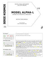
LCI132-0x
INSTRUCTIONS MANUAL
ENTER: Enter programming mode and accepts data.
SHIFT : In programming mode selects mode
or moves the blinking digit
UP : In programming mode increases the value of
the blinking digit
5 seg.
5 seg.
5 seg.
Power Input
200V and 20V
Calibrated
Ranges.
NOT
Configurable
SCAL: Programming method introducing InP1 and InP2 values by keyboard.
tEAC: Programming method where instrument learns actual values of InP1 and Inp2.
InP1 , InP2 : Input signal values corresponding to desired display dSP1 and dSP2 .
dSP1: Display value corresponding to InP1.
dSP2: Display value corresponding to InP2.
LC 0: Programming unlocked.
LC 1: Programming totally locked.( Show all parameters like dAtA) .
Valid for panel meters #258 and so on
/