
For more information, visit www.desatech.com
WARNING: If the information in this manual is not
-
— WHAT TO DO IF YOU SMELL GAS
-
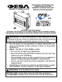
STAINLESS OUTDOOR GAS
FIREPLACE SYSTEM
OWNER’S OPERATION AND
INSTALLATION MANUAL
REMOTE CONTROL READY
NATURAL GAS MODELS (V)O36NRA SERIES AND (V)O42NRA SERIES
PROPANE/LP GAS MODELS (V)O36PRA SERIES AND (V)O42PRA SERIES
PFS
®
USC

www.desatech.com
124868-01A2
SAFETY
-
and maintenance instructions
-
known to the state of California
-
-
Early signs
of carbon monoxide poisoning resemble the
u, with headaches, dizziness or nausea. If
you have these signs, the heater may not
be working properly. Get fresh air at once!
Have heater serviced. Some people are
more affected by carbon monoxide than oth-
ers. These include pregnant women, people
with heart or lung disease or anemia, those
under the inuence of alcohol and those at
high altitudes.
Natural and
propane/LP gases are odorless. An odor-
making agent is added to the gas. The odor
helps you detect a gas leak. However, the
odor added to the gas can fade. Gas may be
present even though no odor exists.
Make certain you read and understand all
warnings. Keep this manual for reference. It
is your guide to safe and proper operation of
this replace.
this heater or its controls can
-
-
-
-
dren when they are in the area
hand-held remote accessory,
TABLE OF CONTENTS
Safety .................................................................. 2
Local Codes......................................................... 3
Product Features ................................................. 4
Locating Fireplace ............................................... 4
Product Specications ......................................... 4
Installation ........................................................... 5
Operation ............................................................11
Inspecting Burners............................................. 13
Cleaning and Maintenance ................................ 13
Wiring Diagram .................................................. 14
Specications .................................................... 14
Troubleshooting ................................................. 15
Parts .................................................................. 18
Replacement Parts ............................................ 23
Service Hints ..................................................... 23
Technical Service............................................... 23
Accessories ....................................................... 23
Warranty ..............................................Back Cover

www.desatech.com
124868-01A 3
-
-
1. This replace is only for use with the type
of gas indicated on the rating plate. This
replace is not convertible for use with
other gases.
2. Do not place propane/LP supply tank(s)
inside any structure. Locate propane/LP
supply tank(s) outdoors (propane/LP units
only).
3. If you smell gas
• shut off gas supply
• do not try to light any appliance
• do not touch any electrical switch; do not
use any phone in your building
• immediately call your gas supplier from
a neighbor’s phone. Follow the gas sup-
plier’s instructions
• if you cannot reach your gas supplier,
call the re department
4. This replace shall be used only outdoors
in a well ventilated space and shall not be
used in a building, garage or any other
enclosed area.
5. Do not use this replace as a wood burn-
ing replace. Use only the logs provided
with the replace. Do not burn solid fuels
in this replace.
SAFETY
Continued
6. Do not add extra logs or ornaments such
as pine cones, vermiculite or rock wool.
Using these added items can cause soot-
ing. Do not add lava rock around base.
Rock and debris could fall into the control
area of replace.
7. To prevent the creation of soot, follow the
instructions in Cleaning and Maintenance,
page 13.
8. Before using furniture polish, wax, carpet
cleaner or similar products, turn replace
off. If heated, the vapors from these prod-
ucts may create a white powder residue
within burner box or on adjacent walls or
furniture.
9. Do not run replace
• where ammable liquids or vapors are
used or stored
• under dusty conditions
10. Do not use this replace to cook food or
burn paper or other objects.
11. Do not use this appliance if any part has
been under water. Immediately call a
qualied service technician to inspect the
appliance and to replace any part of the
control system and any gas control which
has been under water.
12. Do not operate fireplace if any log is
broken. Do not operate replace if a log
is chipped (dime-sized or larger).
13. Turn fireplace off and let cool before
servicing. Only a qualied service person
should service and repair replace.
14. Operating replace above elevations of
4,500 feet could cause pilot outage.
15. Provide adequate clearance around air
openings.
LOCAL CODES
Install and use replace with care. Follow all
local codes. In the absence of local codes,
use the latest edition of The National Fuel
Gas Code ANSI Z223.1/NFPA 54*.
*Available from:
American National Standards Institute, Inc.
1430 Broadway
New York, NY 10018
National Fire Protection Association, Inc.
Batterymarch Park
Quincy, MA 02269
State of Massachusetts: The installation
must be made by a licensed plumber or
gas tter in the Commonwealth of Mas-
sachusetts.
Sellers of unvented propane or natural
gas-red supplemental room heaters shall
provide to each purchaser a copy of 527
CMR 30 upon sale of the unit.
Vent-free gas products are prohibited for
bedroom and bathroom installation in the
Commonwealth of Massachusetts.

www.desatech.com
124868-01A4
PRODUCT FEATURES
Your replace features a concrete refractory
brick liner. As with all concrete liners, this liner
may develop slight cracks when exposed to
heat. These cracks will not affect the perfor-
mance of the replace.
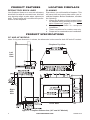
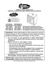
Figure 1 - Fireplace Dimensions (36" and 42" Models)
Fireplace Top View
Front View
Right
Side
View
Left
Side
View
LOCATING FIREPLACE
PLANNING
Plan where you will install the replace. This
will save time and money later when you in-
stall the replace. Before installation, consider
the following:
1. Where the replace will be located. Allow
for wall and ceiling clearances (see Instal-
lation Clearances, page 5).
2. E v e r y t hi n g ne ed e d to c om p le t e
installation.
3. These models are for outdoor use only.
4. Proper air for combustion and ventilation.
PRODUCT SPECIFICATIONS
36" AND 42" MODELS
Note: If only one dimension is shown, the dimension is the same for both 36" and 42" models.

www.desatech.com
124868-01A 5
INSTALLATION
CAUTION: Do not install the
Mantel Clearances for Built-In
Installation
If placing custom mantel above built-in re-
place, you must meet the minimum allowable
clearance between mantel shelf and top of
replace opening shown in Figure 3, page
6. These are the minimum allowable mantel
clearances for a safe installation. Use larger
clearances wherever possible to minimize
the heating of objects and materials placed
on the mantel.
minimum clearances shown in
NOTICE: If your installation does
not meet the minimum clear-
ances shown, you must do one
-
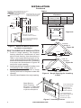
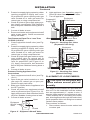
Figure 2 - Minimum Clearance for
Combustible to Wall
*Minimum 16" from Side Wall
*
Example
IMPORTANT: Make sure replace is level.
If replace is not level, log set will not work
properly.
Use dimensions shown for rough openings
to create the easiest installation (see Built-In
Fireplace Installation, page 6).
INSTALLATION CLEARANCES
WARNING: Maintain the
Carefully follow these instructions. This will
ensure safe installation. Fireplace hood
must be used if combustible mantel material
is installed.
A. Clearances from the side of the replace
cabinet to any combustible material and
wall should follow diagram in Figure 2.
Example: The face of a mantel, bookshelf,
etc. is made of combustible material and
protrudes 3
1
/
2
" from the wall. This com-
bustible material must be 4" from the side
of the replace cabinet (see Figure 2).
B. Clearances from the top of the replace
opening to the ceiling should not be less
than 42".
C. When replace is installed on carpet-
ing or other combustible material, other
than wood ooring, replace should be
installed on a metal or wood panel extend-
ing the full width and depth of enclosure.
D. Clearances from bottom of replace to the
oor is 0".

www.desatech.com
124868-01A6
BUILT-IN FIREPLACE INSTALLATION
1. Frame in rough opening. The fireplace
framing should be constructed of steel
stud or steel framing. Use dimensions in
Table 1 and rough opening layout in Fig-
ure 4a. Adjust framing so that fireplace is
flush with finished wall surface. If installing
in a corner, use dimensions in Figures 4b
and 4c for rough opening.
2. Install gas piping to fireplace location (see
Connecting to Gas Supply, page 7).
3. Carefully set fireplace in front of rough
opening with back of fireplace inside wall
opening.
4.
Carefully insert fireplace into rough opening.
INSTALLATION
Continued
Rough Opening Dimensions for Built-in
Installation
Model
Front Width
(Inside to Inside) Height
Depth
(Min.)
36" 41
1
/
2
" 40
1
/
2
" 20
3
/
4
"
42" 48
5
/
8
" 44
1
/
2
" 22
5
/
8
"
Table 1
Figure 4 - Rough Opening for Installing
in Wall
Depth
(Minimum)
Width
(Inside to Inside)
Height
Figure 4a
37"
45°
41
1
/
2
"
5
2
1
1
/
3
2
"
74"
TOP VIEW
FOR 36"
MODELS
Figure 4b
43"
45°
48
5
/8"
6
0
1
3
/
1
6
"
86"
TOP VIEW
FOR 42"
MODELS
Figure 4c
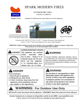
Figure 5 - Installing Firebox
Steel Stud or
Steel Framing
Required. Combustible
materials not allowed
adjacent to replace.
Figure 3 - Minimum Mantel Clearances
for Built-In Installation
Hood MUST be used if a
combustible mantel is installed.
Wire-mesh
Screen
Firebox
Noncombustible
Material May
Project Off this
Surface above
the Firebox Hood
Mantel Shelf Note: Any portion
of the mantel shelf must NOT
extend beyond this profile.
1
1
/
2
"
6
3
/
4
"
12"
Note: All vertical measurements are
from top of fireplace hood opening to
bottom of mantel shelf.
Wall board or facing material within 12 inches
must be of noncombustible
material, including decorative mantel
ornaments or other similar projections
the facing material.
Framing
Material
12"
12" Minimum
16" 20"
12 inch minimum
noncombustible
wall board or
facing material
above replace.
12 inch minimum
noncombustible wall
board or facing
material on sides.

www.desatech.com
124868-01A 7
INSTALLATION
Continued
INSTALLING DRAIN PAN DP36/DP42
The replace enclosure must allow for ad-
equate drainage and fresh air ventilation.
It is recommended that a sealed, corrosion
resistant catch pan with provision for drainage
be installed under replace within replace
enclosure (see Accessories, page 23).
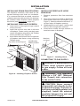
INSTALLING FIREPLACE SCREEN
1. Insert each rod through all rings located
at top of screen.
2. Insert rst rod into rear hole in left side
of replace. Fasten rod to rear hole near
center of replace using #10 x 3/8" Phillips
screw provided (see Figure 6).
3. Insert other rod into front hole on right side
of replace and fasten using remaining
Phillips screw.
Figure 6 - Installing Fireplace Screen
Screw
Rear Hole
Top View of Rod Layout
Rod
Front
Hole
Ring
Screen
Identication
Label Location
INSTALLING FIREPLACE HOOD
HS36/HS42
1. Remove protective lm from stainless
hood.
2. Align three notches located on back side
of hood with front face of replace (see
Figure 7). Notches should be at least 3
1
/
2
"
up from edge of replace opening.
3. Hold replace hood in place. Using a #10
drill bit, drill through three notches.
4. Insert three screws through notches in
hood into holes in replace.
Figure 7 - Installing Hood
Notches
on Hood
Screws
CONNECTING TO GAS SUPPLY
-

www.desatech.com
124868-01A8
INSTALLATION
Continued
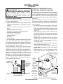
Figure 9 - Propane/LP Tank Enclosure
Minimum of 5" (12.7 cm)
From Floor T o T o p O
f
Bottom Opening
Minimum of
2" (5 cm)
From Floor
Bottom T o
Ground Level
Minimum 1/8"
(0.3 cm)
Permissible
Openings
T o p
Openings
At Valve
Level
2 Openings
T o p and
Bottom on
Each Side
Minimum
0.5 inch
2
(3.23 cm
2
)
of Free Air
Space For
Each Pound
of Fuel But No
Less Than
10 inches
2
(65 cm
2
) Total
Installation Items Needed
Before installing heater, make sure you have
the items listed below.
• approved exible gas hose and ttings
(supplied with appliance, if allowed by local
codes)
• external regulator (propane/LP models
only)
• piping (check local codes)
• sealant (resistant to propane/LP gas)
• equipment shutoff valve*
• test gauge connection*
• sediment trap
• tee joint
• pipe wrench
* A CSA design-certied equipment shutoff
valve with 1/8" NPT tap is an acceptable al-
ternative to test gauge connection. Purchase
the optional CSA design-certied equipment
shutoff valve from your dealer.
For propane/LP units, the installer must
supply an external regulator. The external
regulator will reduce incoming gas pressure.
You must reduce incoming gas pressure to
between 11" and 14" of water. If you do not
reduce incoming gas pressure, control valve
damage could occur. Install external regula-
tor with the vent pointing down as shown in
Figure 8. Pointing the vent down protects it
from freezing rain or sleet.
Propane/LP
Supply Tank
External
Regulator
with Vent
Pointing
Down
Figure 8 - External Regulator with Vent
Pointing Down
REMOTE PROPANE/LP GAS
SUPPLIES AND ENCLOSURES
If appliance is to be permanently connected
to a gas piping system from a remote supply
tank, installation must be in accordance with
local codes or, in absence of local codes, with
the National Fuel Gas Codes ANSI Z223.1/
NFPA 54.
Enclosures may be used to conceal propane/
LP supply tanks and must be constructed to
meet the following minimum construction
requirements:
• An enclosure must have either one open
side or at least four opposing vent open-
ings, top and bottom, which meet minimum
requirements for size and location (see
Figure 9).
• Each opening must provide a minimum or
1/2 inches
2
(3,23 cm
2
) of open area for each
pound propane/LP contained in enclosed
supply tank.
Example: A full enclosure for a 20 pound
propane/LP tank must have at least four,
10 inches
2
(65 cm
2
) openings [a 2" x 5" (5 x
13 cm) square].
• The top openings must be 180° opposing
and be placed at valve level.
• The bottom openings must be 180° op-
posing and be placed 5" (12.7 cm) above
bottom oor.
• There must be 2" (5 cm) minimum clear-
ance from the floor to ground level of
enclosure.

www.desatech.com
124868-01A 9
INSTALLATION
Continued
CAUTION: Use only new,
-
Installation must include an equipment shutoff
valve, union and plugged 1/8" NPT tap. Locate
NPT tap within reach for test gauge hook up.
NPT tap must be upstream from log set (see
Figure 10).
IMPORTANT: Install equipment shutoff valve
in an accessible location. The equipment
shutoff valve is for turning on or shutting off
the gas to the appliance.
Apply pipe joint sealant lightly to male NPT
threads. This will prevent excess sealant from
going into pipe. Excess sealant in pipe could
result in clogged heater valves.
We recommend that you install a sediment
trap in supply line as shown in Figure 10.
Locate sediment trap where it is within reach
for cleaning. Install in piping system between
fuel supply and appliance. Locate sediment
trap where trapped matter is not likely to
freeze. A sediment trap traps moisture and
contaminants. This keeps them from going
into heater controls. If sediment trap is not
installed or is installed wrong, heater may
not run properly.
and connections for leaks after
-
CAUTION: Make sure exter-
under Connecting to Gas Sup-
ply
PRESSURE TESTING GAS SUPPLY
PIPING SYSTEM
1. Disconnect appliance with its appliance
main gas valve (control valve) and equip-
ment shutoff valve from gas supply piping
system. Pressures in excess of 1/2 psig
will damage control valve.
2. Cap off open end of gas pipe where equip-
ment shutoff valve was connected.
Figure 10 - Gas Connection
* Purchase the optional CSA design-certied
shutoff valve from your dealer.
** Minimum inlet pressure for purpose of input
adjustment.
Approved Flexible
Gas Hose (If
allowed by local
codes)
CSA Design-Certied
Equipment Shutoff
Valve with 1/8" NPT
Tap*
Natural
From Gas
Meter (5" W.C.**
to 10.5" W.C.
Pressure)
From External
Regulator (11"
W.C.** to 14"
W.C. Pressure)
3" Min.
Pipe Cap Tee
Nipple Joint
Sediment Trap

www.desatech.com
124868-01A10
Figure 11 - Equipment Shutoff Valve
Equipment
Shutoff
Valve
Open
Closed
Figure 13 - Checking Gas Joints
(Natural Gas Only)
Control Valve
Location
Equipment
Shutoff Valve
Propane/LP
Supply Tank
Equipment
Shutoff Valve
Gas Meter
Figure 12 - Checking Gas Joints
(Propane/LP Gas Only)
Control Valve
Location
3. Pressurize supply piping system by either
opening propane/LP supply tank valve
for propane/LP gas or opening main gas
valve located on or near gas meter for
natural gas or using compressed air.
4. Check all joints of gas supply piping sys-
tem. Apply noncorrosive leak detection
uid to all joints. Bubbles forming show a
leak.
5. Correct all leaks at once.
6. Reconnect heater and equipment shutoff
valve to gas supply. Check reconnected
ttings for leaks.
1. Close equipment shutoff valve (see Fig-
ure 11).
2. Pressurize supply piping system by either
opening propane/LP supply tank valve
for propane/LP gas or opening main gas
valve located on or near gas meter for
natural gas or using compressed air.
3. Check all joints from gas meter to equip-
ment shutoff valve for natural gas or
propane/LP supply to equipment shutoff
valve for propane/LP (see Figure 12 or
13). Apply noncorrosive leak detection
uid to all joints. Bubbles forming show a
leak.
4. Correct all leaks at once.
Connections
1. Open equipment shutoff valve (see Fig-
ure 11).
2. Open main gas valve located on or near
gas meter for natural gas or open pro-
pane/LP supply tank valve.
3. Make sure control knob of appliance is in
the OFF position.
4. Check all joints from equipment shutoff
valve to gas control (see Figure 12 or 13).
Apply noncorrosive leak detection uid to
all joints. Bubbles forming show a leak.
5. Correct all leaks at once.
6. Light appliance (see Operation, page 11)
Check all other internal joints for leaks.
7. Turn off appliance.
INSTALLATION
Continued
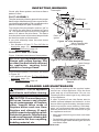
PLACEMENT OF LOOSE EMBERS
-
Two bags of loose embers are provided with
this unit. For this installation use the embers
that are approximately 1" square in size. If
needed, larger embers can be broken to size.
These embers aid in concealing the burner
pan, directing ames through the ember bed,
quiet operation of the unit and gives a natural
random ame pattern.
Place embers as follows:
1. Place embers around center ember bed
or ember pod.

www.desatech.com
124868-01A 11
INSTALLATION
Continued
Figure 14 - Placement of Embers
2. Place individual embers on their edge (not
at) along the top of burner pan. This aids
in directing ames from the burner through
ember bed.
Note: Too many embers or embers placed
at along burner pan can suppress the
ames.
3. When unit is lit, check ames for random
appearance and ember bed glowing red-
orange in color (see Burner Flame Pattern,
page 13). If this is not happening, either
add, remove or reposition loose embers.
IMPORTANT: Turn unit off and let cool
before repositioning loose embers.
OPERATION
FOR YOUR SAFETY
READ BEFORE LIGHTING
WARNING: If you do not fol-
low these instructions exactly,
-
-
WHAT TO DO IF YOU SMELL GAS
-
LIGHTING
INSTRUCTIONS
1. STOP! Read the safety information,
above.
2. Make sure switch is in the OFF position.
3. Be sure gas line shut-off valve is OPEN.
4.
Press in and turn control knob clock-
wise to the OFF position (see
Figure 15).
Note: Knob cannot be turned from PILOT
to OFF unless knob is pushed in slightly.
DO NOT FORCE.
5. Wait ve (5) minutes to clear out any gas.
If you then smell gas, STOP! Follow "B" in
the safety information in column 1. If you
don't smell gas, go on the next step.
6. Press in and turn control knob counter-
clockwise to the PILOT position.
Press in control knob for ve (5) seconds
(see Figure 15).
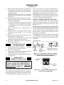
Figure 15 - Setting Control Knobs
Piezo
Ignitor
Control
Knob
Flame Adjustment Knob

www.desatech.com
124868-01A12
Note: The burner may light if hand-held re-
mote was on when selector switch was last
turned off. You can now turn the burner on and
off with the hand-held remote control unit.
IMPORTANT: Do not leave the selector switch
in the REMOTE or ON position when the pilot
is not lit. This will drain the battery.
Hold the control button on the hand-held
remote until burner turns on. Hold the con-
trol button again until burner turns off (see
Figure 17).
To Lock press both buttons on hand-held
remote control until light stops ashing. Hand-
held remote control is now locked. If the re
is on it will be turned off automatically. In the
locked state, the light will not light up when
any button is pressed.
To Unlock press both buttons together
on hand-held remote control until the light
stops ashing. The hand-held remote is now
unlocked.
Figure 16 - Setting the Selector Switch,
Control Knob and Flame Adjustment
Knob for Remote Operation
Selector Switch in
REMOTE Position
REMOTE
OFF
ON
Piezo
Ignitor
Control Knob
Flame
Adjustment
Knob
Figure 17 - On/Off Hand-Held Remote
Control Unit (HRC100)
Control
Button
Indicator
Light
OPERATION
Continued
7. With control knob pressed in, press and
release ignitor button. This will light pilot.
If needed, keep pressing ignitor button
until pilot lights.
Note: If pilot does not stay lit, contact a
qualied service person or gas supplier
for repairs.
8. Keep control knob pressed in for 30 sec-
onds after lighting pilot. After 30 seconds,
release control knob.
• If control knob does not pop out when
released, turn off gas supply and contact
a qualied service person or gas supplier
for repairs.
Note: If pilot goes out, repeat steps 4
through 8.
9. Slightly push in and turn control knob
counterclockwise to the ON
position.
10. Wait one minute and move switch to the
ON position to light burner.
Note: AUTO is only functional when using
optional remote control accessory.
11. Set ame adjustment knob to any level
between HI and LO.
TO TURN OFF GAS
TO APPLIANCE
1. Push switch into OFF position. The pilot
will remain lit for normal service.
2. Access control knobs.
3. Press gas control knob slightly and turn
clockwise to OFF. Do not force.
4. Close equipment shutoff valve (see Figure
11, page 10).
HAND-HELD
REMOTE OPERATION
-
Lighting
Instructions
After lighting, let pilot ame burn for about
one minute. Turn control knob to ON posi-
tion. Adjust ame adjustment knob anywhere
between HI and LO. Slide the selector switch
to the REMOTE position (see Figure 16).

www.desatech.com
124868-01A 13
Thermocouple
Thermopile
1/8"
Pilot Burner
Piezo
Ignitor
Figure 18 - Pilot Assembly
3/8" to 1/2"
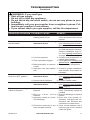
INSPECTING BURNERS
Check pilot ame pattern and burner ame
patterns often.
PILOT ASSEMBLY
The pilot assembly is factory preset for the proper
ame height. Alterations may have occurred dur-
ing shipping and handling. Call a qualied service
person to readjust the pilot if necessary.
The height of the thermopile must be 3/8" to
1/2" above the pilot ame as shown in Figure
18. The thermocouple must be at a height of
about 1/8" above the pilot ame. The ame
from the pilot burner must extend beyond both
the thermocouple and thermopile.
If you pilot assembly does not meet these
requirements:
• turn replace off (see To Turn Off Gas to
Appliance, page 12).
• see Troubleshooting, page 15.
BURNER FLAME PATTERN
Figure 19 shows correct burner ame pattern.
If burner ame pattern is incorrect, as shown
in Figure 20
• turn appliance off (see To Turn Off Gas to
Appliance, page 12).
• see Troubleshooting, page 15.
Figure 19 - Correct Burner Flame Pattern
Yellow Flames with
Orange Streaks
Figure 20 - Incorrect Burner Flame
Pattern
Dark Orange
Flames
CLEANING AND MAINTENANCE
Only limited cleaning will be required under
normal use of this appliance. Dust the front
grate and top of receiver/valve. Do not use
cleaning uids to clean logs or any other part
of the appliance.
If, after a period of use, the ames start to
exhibit unusual shapes and behavior or the
burner fails to ignite smoothly, then the burner
holes may require some cleaning. If this hap-
pens, we recommend that you contact your
nearest authorized service technician to get
the appliance serviced.
• Keep area around log set clean and clear
of debris.
• Periodically inspect the air mixer and burner
tube for foreign matter blocking the air inlet
and ame holes.
-
-
-
-

www.desatech.com
124868-01A14
WIRING DIAGRAM
SPECIFICATIONS
(V)O36NRA Series
• Rating (Variable): 28,000/41,000 Btu/Hr
• Gas Type: Natural
• Ignition: Piezo
• Manifold Pressure: 3.5" W.C.
• Inlet Gas Pressure (inches of water):
Max. 10.5" W.C., Min. 5.0" W.C.*
• Air Shutter: 3/16" OPEN
(V)O36PRA Series
• Rating (Variable): 32,000/41,000 Btu/Hr
• Gas Type: Propane/LP
• Ignition: Piezo
• Manifold Pressure: 10" W.C.
• Inlet Gas Pressure (inches of water):
Max. 14" W.C., Min. 11" W.C.*
• Air Shutter: FULLY OPEN
(V)O42NRA Series
• Rating (Variable): 32,000/47,000 Btu/Hr
• Gas Type: Natural
• Ignition: Piezo
• Manifold Pressure: 3.5" W.C.
• Inlet Gas Pressure (inches of water):
Max. 10.5" W.C., Min. 5.0" W.C.*
• Air Shutter: 3/16" OPEN
(V)O42PRA Series
• Rating (Variable): 35,000/45,000 Btu/Hr
• Gas Type: Propane/LP
• Ignition: Piezo
• Manifold Pressure: 10" W.C.
• Inlet Gas Pressure (inches of water):
Max. 14" W.C., Min. 11" W.C.*
• Air Shutter: FULLY OPEN
*For purpose of input adjustment
HEAT LIMIT SWITCH
TO PILOT
SUPPLY
MAIN GAS
INCOMING
CONTROL
VALVE
TPTH
TP
TH
OPTIONAL
ON/OFF
SWITCH
OPTIONAL
RECEIVER
REMOTER
WHITE
BLACK
BLACK
ELECTRICAL WIRE CONNECTION WILL
REQUIRE MALE TO MALE CONNECTORS

www.desatech.com
124868-01A 15
OBSERVED PROBLEM POSSIBLE CAUSE REMEDY
When ignitor button is
pressed, there is no spark
at pilot.
1. Ignitor electrode not con-
nected to ignitor cable.
2. Ignitor cable pinched or wet
3. Piezo ignitor nut is loose.
4. Broken ignitor cable.
5. Bad piezo ignitor.
6. Ignitor electrode broken.
7. Ignitor electrode positioned
wrong.
1. Reconnect ignitor cable.
2. Free ignitor cable if pinched
by any metal or tubing. Keep
ignitor cable dry.
3. Tighten nut holding piezo
ignitor. Nut is located behind
the mounting bracket.
4. Replace ignitor cable.
5. Replace piezo ignitor.
6. Replace pilot assembly.
7. Tighten electrode. Replace if
necessary.
When ignitor button is
pressed, there is spark at
pilot but no ignition.
1. Gas supply turned off or
equipment shutoff valve
closed.
2. Gas control knob not in PI-
LOT position.
3. Gas control knob not pressed
in while in PILOT position.
4. Air in gas lines when in-
stalled.
5. Depleted gas supply (pro-
pane/LP models only).
6. Pilot is clogged.
7. Gas regulator setting is not
correct.
1. Turn on gas supply or open
equipment shutoff valve.
2. Turn gas control knob to
PILOT position.
3. Press in gas control knob
while in PILOT position.
4. Continue holding down con-
trol knob. Repeat igniting op-
eration until air is removed.
5. Contact local propane/LP gas
company.
6. Clean pilot (see Cleaning
and Maintenance, page 13)
or replace pilot assembly.
7. Replace gas regulator.
Burner does not light after
pilot is lit.
1. Burner orice clogged.
2. Inlet gas pressure is too
low.
3. Thermopile leads discon-
nected or improperly con-
nected.
4. Thermopile is defective.
1. Clean burner (see Cleaning
and Maintenance, page 13)
or replace burner orice.
2. Contact local propane/LP or
natural gas company.
3. Reconnect leads to TP &
TPTH terminals on control
valve.
4. Replace thermopile.
TROUBLESHOOTING
Note: All troubleshooting items are listed in order of operation.

www.desatech.com
124868-01A16
TROUBLESHOOTING
Continued
OBSERVED PROBLEM POSSIBLE CAUSE REMEDY
Pilot lights but ame goes
out when control knob is
released.
1. Gas control knob not fully
pressed in.
2. Gas control knob not pressed
in long enough.
3. Equipment shutoff valve not
fully open.
4. Pilot ame not touching ther-
mocouple, which allows ther-
mocouple to cool, causing
pilot flame to go out. This
problem could be caused by
one or both of the following:
A) Low gas pressure
B) Dirty or partially clogged
pilot
5. Thermocouple connection
loose at control valve.
6. Thermocouple damaged.
7. Control valve damaged.
1. Press in gas control knob
fully.
2. After pilot lights, keep gas
control knob pressed in 30
seconds.
3. Fully open equipment shutoff
valve.
4. A) Contact local natural or
propane/LP gas company
B) Clean pilot (see Cleaning
and Maintenance, page 13)
or replace pilot assembly.
5. Hand tighten until snug, then
tighten 1/4 turn more.
6. Replace pilot assembly.
7. Replace control valve.
Delayed ignition burner. 1. Manifold pressure is too
low.
2. Burner porting or orifice
clogged.
3. Orice misaligned.
4. Air shutter setting incorrect.
1. Contact local propane/LP or
natural gas company.
2. Clean burner (see Cleaning
and Maintenance, page 13)
or replace burner orice.
3. Straighten alignment.
4. Set air shutter to correct
opening (see Specications,
page 14).
Burner backfiring during
combustion.
1. Burner orice is clogged or
damaged.
2. Damaged burner.
3. Gas regulator defective.
1. Clean burner (see Cleaning
and Maintenance, page 13)
or replace burner orice.
2. Replace damaged burner.
3. Replace gas control.
Slight smoke or odor during
initial operation.
1. Residues from manufacturing
processes and logs curing.
1. Problem will stop after a few
hours of operation.
Heater produces a whistling
noise when burner is lit.
1. Turning gas control knob to HI
position when burner is cold.
2. Air in gas line.
3. Dirty or partially clogged
burner orice.
1. Turn gas control knob to LO
position and let warm up for a
minute.
2. Operate burner until air is
removed from line. Have gas
line checked by local propane/
LP or natural gas company.
3. Clean burner (see Cleaning
and Maintenance, page 13)
or replace burner orice.
Fireplace produces a click-
ing/ticking noise just after
burners are lit or shut off.
1. Metal expanding while heat-
ing or contracting while
cooling.
1. This is normal. If noise is
excessive, contact qualied
service person.

www.desatech.com
124868-01A 17
OBSERVED PROBLEM POSSIBLE CAUSE REMEDY
Remote does not function. 1. Battery is not installed or
battery power is low.
1. Replace 9-volt batteries in re-
ceiver and hand-held remote
control.
Fireplace produces un-
wanted odors.
1. Gas leak.
1. Locate and correct all leaks
(see Checking Gas Connec-
tions, page 9).
Fireplace shuts off in use. 1. High or gusting winds.
2. Low line pressure.
3. Pilot is partially clogged.
4. Bad thermopile or thermo-
couple.
5. Improper vent cap installa-
tion.
1. Fireplace has been tested for
up to 40 mph winds. However,
extreme conditions may oc-
cur. See Lighting Instructions
on page 11.
2. Contact local propane/LP or
natural gas company.
3. Clean pilot (see Cleaning and
Maintenance, page 13).
4. Replace faulty component.
5. Check for proper installation
and freedom from debris or
blockage.
Gas odor even when control
knob is in OFF position.
1. Gas leak.
2. Control valve defective.
1. Locate and correct all leaks
(see Checking Gas Connec-
tions, page 9).
2. Replace control valve.
Gas odor during combustion.
1. Gas leak.
1. Locate and correct all leaks
(see Checking Gas Connec-
tions, page 9).
Dark residue on logs or
inside of replace.
1. Air holes at burner inlet
blocked.
2. B u r n e r f l a m e h o l e s
blocked.
3. Improper venting or exces-
sive blockage.
4. Excessive amounts of em-
bers and pan material.
1. Clean out air holes at burner
inlets. Periodically repeat as
needed.
2. Remove blockage or replace
burner.
3. Have the vent system in-
spected, including the ter-
mination cap. Remove any
restrictions or obstruction.
4. Clear excess embers until a
minimum gap of 1/2" remains
under the grate.
TROUBLESHOOTING
Continued
-

www.desatech.com
124868-01A18
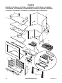
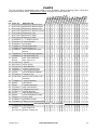
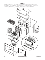
PARTS
MODELS VO36NRA, VO36PRA, VO36NRRA, VO36PRRA, VO36NRHA,
VO36PRHA, VO36NRRHA, VO36PRRHA, O36NRA, O36PRA, O36NRHA,
O36PRHA, O36NRRA, O36PRRA, O36NRRHA AND O36PRRHA
27
28
29
30
24
21
25
5
6
7
8
9
13
26
17
18
19
2
1
3
4
23
18
31
32
10
11
12
14
33
22
16
20
15
29

www.desatech.com
124868-01A 19
DESCRIPTION
1
See Page 22
Refractory, Bottom Rear • • • • • • • • • • • • • • • • 1
2
See Page 22
Refractory, Bottom Right • • • • • • • • • • • • • • • • 1
3
See Page 22
Refractory, Bottom Left • • • • • • • • • • • • • • • • 1
4
See Page 22
Refractory, Bottom Center • • • • • • • • • • • • • • • • 1
5
See Page 22
Refractory, Left • • • • • • • • • • • • • • • • 1
6
See Page 22
Refractory, Right • • • • • • • • • • • • • • • • 1
7
See Page 22
Refractory, Rear • • • • • • • • • • • • • • • • 1
8 114936-02 1
1
/
4
" Elbow Venturi • • • • • • • • • • • • • • • • 1
9 112370-01 Venturi Gasket • • • • • • • • • • • • • • • • 1
10 116559-01 Air Shutter • • • • • • • • • • • • • • • • 1
11 114365-11 Brass Orice NG • • • • • • • • 1
114365-12 Brass Orice LP • • • • • • • • 1
12 111824-01 3/8" Compression Nut/
Sleeve
• • • • • • • • • • • • • • • • 1
13 108084-02 Pilot Assembly (Natural) • • • • • • • • 1
108084-03 Pilot Assembly (LP) • • • • • • • • 1
14 14389 Gas Valve (Natural) • • • • • • • • 1
14390 Gas Valve (LP) • • • • • • • • 1
15 117427-02 Log Set • • • • • • • • • • • • • • • • 1
16 097159-04 Piezo Ignitor • • • • • • • • • • • • • • • • 1
17 107741-03 Valve Bracket • • • • • • • • • • • • • • • • 1
18 106683-01 Firebox Support Leg • • • • • • • • • • • • • • • • 4
19 108033-01 Leg Support Bracket • • • • • • • • • • • • • • • • 2
20 14396 3/8 x 3/8 Brass Adapter • • • • • • • • • • • • • • • • 1
21 107940-01 Fireplace Top • • • • • • • • • • • • • • • • 1
22 111817-08 Dormont T6-18 3.8 x 18"
Flextube
• • • • • • • • • • • • • • • • 1
23 119686-01 Log Set Retainer • • • • • • • • • • • • • • • • 2
24 20280 Top Spacer • • • • • • • • • • • • • • • • 4
25 20027 Firebrick Retainer • • • • • • • • • • • • • • • • 2
26 119702-01 High Limit Switch • • • • • • • • • • • • • • • • 1
27 106641-01 Fireplace Surround • • • • • • • • • • • • • • • • 1
28 117891-01 Handle Bracket • • • • • • • • • • • • • • • • 4
29 21171 Gas Conduit Cover • • • • • • • • • • • • • • • • 4
30 20042 Cover Outside Air Plate • • • • • • • • • • • • • • • • 5
31 106691-01 Screen Rod • • • • • • • • • • • • • • • • 2
32 110890-01 Stainless Screen • • • • • • • • • • • • • • • • 2
33 116786-01
Fitting, 1/2" FLR x 3/8" MPT
• • • • • • • • • • • • • • • • 1
PARTS AVAILABLE — NOT SHOWN
108005-01 Wire Harness • • • • • • • • • • • • • • • • 1
14253 Flex Gas Line • • • • • • • • • • • • • • • • 1
112799-01 Ember Flakes Kit • • • • • • • • • • • • • • • • 2
PARTS
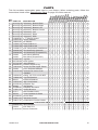
This list contains replaceable parts used in your replace. When ordering parts, follow the
instructions listed under Replacement Parts on page 23 of this manual.
VO36NRA
VO36PRA
VO36NRHA
VO36PRHA
O36NRA
O36PRA
O36NRHA
O36PRHA
O36NRRA
O36PRRA
O36NRRHA
O36PRRHA
VO36NRRA
VO36PRRA
VO36NRRHA
VO36PRRHA

www.desatech.com
124868-01A20
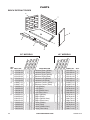
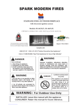
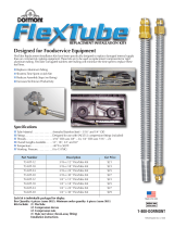
PARTS
MODELS VO42NRA, VO42PRA, VO42NRRA, VO42PRRA, VO42NRHA,
VO42PRHA, VO42NRRHA, VO42PRRHA, O42NRA, O42PRA, O42NRHA,
O42PRHA, O42NRRA, O42PRRA, O42NRRHA AND O42PRRHA
5
7
6
25
34
3
4
12
11
10
20
16
9
8
13
18
18
17
14
22
21
1
2
29
31
30
15
23
32
33
26
27
28
34
19
24
Page is loading ...
Page is loading ...
Page is loading ...
Page is loading ...
-
 1
1
-
 2
2
-
 3
3
-
 4
4
-
 5
5
-
 6
6
-
 7
7
-
 8
8
-
 9
9
-
 10
10
-
 11
11
-
 12
12
-
 13
13
-
 14
14
-
 15
15
-
 16
16
-
 17
17
-
 18
18
-
 19
19
-
 20
20
-
 21
21
-
 22
22
-
 23
23
-
 24
24


Ask a question and I''ll find the answer in the document
Finding information in a document is now easier with AI
Related papers
-
Desa (V)KC42PE SERIES, (V)KC42NE SERIES User manual
-
-
Desa L32 User manual
-
-
-
-
FMI VSGF36PRA User manual
-
-
-
Other documents
-
 Spark LBS-OD36 Owner's Operation And Installation Manual
-
-
FMI O36NRB Owner's manual
-
 Spark Modern Fires SS-36P Owner's Operation And Installation Manual
-
 Design Dynamics DVF-36S-N User manual
-
Vantage Hearth VFS32PRK User manual
-
 Spark Modern Fires FT60 5ft Installation guide
-
Emberglow CVS303 Installation guide
-
 Dormont Mfg T3-KIT-18 Installation guide
-


