Page is loading ...

3.568.5275.226
© Copyright 2016
EXPER
TISE SOLUTIONS SUST
AINABILITY
IM-P343-16
CH Issue 7 - 2016
1. Safety information
2. Introduction
3. Installation
4. Commissioning
5. Maintenance
6. Spare parts
7. Faultnding
EP5 and ISP5 Series
Electropneumatic Positioners
Installation and Maintenance Instructions
Attention: Additional instructions are required when a ATEX
intrisically safety instrument ISP5 is used in an explosion risk area.

3.568.5275.226
2
1. Safety information
Safe operation of these products can only be guaranteed if they are properly installed, commissioned,
usedandmaintainedbyqualiedpersonnel(seeparagraph1.11)incompliancewiththeoperating
instructions.Generalinstallationandsafetyinstructionsforpipelineandplantconstruction,aswell
astheproperuseoftoolsandsafetyequipmentmustalsobecompliedwith.
WARNING: The maximum process uid temperature must be suitable for use if the
unit is to be used in any potential explosive atmosphere. For the device maintenance
inapotentiallyexplosiveatmosphere,werecommendtheusageoftoolswhichdonot
produce and / or propagate sparks.
1.1 Intended use
Referring to the Installation and Maintenance Instructions, name-plate and Technical Information
Sheet, check that the product is suitable for the intended use / application. The products comply
withtherequirementsoftheEuropeanDirective2014/34/EU(ATEX).
1.2 Access
Ensuresafeaccessandifnecessaryasafeworkingplatform(suitablyguarded)beforeattempting
toworkontheproduct.Arrangesuitableliftinggearifrequired.
1.3 Lighting
Ensureadequatelighting,particularlywheredetailedorintricateworkisrequired.
1.4 Hazardous liquids or gases in the pipeline
Considerwhatisin thepipeline orwhat mayhave beenin thepipeline atsome previoustime.
Consider:ammablematerials,substanceshazardoustohealth,extremesoftemperature.
1.5 Hazardous environment around the product
Consider:explosion riskareas, lack ofoxygen (e.g.tanks, pits),dangerous gases,extremes of
temperature,hotsurfaces,rehazard(e.g.duringwelding),excessivenoise,movingmachinery.
1.6 The system
Considertheeectonthecompletesystemoftheworkproposed.Willanyproposedaction(e.g.
closingisolationvalves,electricalisolation)putanyotherpartofthesystemoranypersonnelatrisk?
Dangersmightincludeisolationofventsorprotectivedevicesortherenderingineectiveofcontrols
oralarms.Ensureisolationvalvesareturnedonandoinagradualwaytoavoidsystemshocks.
1.7 Pressure systems
Ensurethatanypressureisisolatedandsafelyventedtoatmosphericpressure.Considerdouble
isolation(doubleblockandbleed)andthelockingorlabellingofclosedvalves.Donotassumethat
thesystemhasdepressurisedevenwhenthepressuregaugeindicateszero.
1.8 Temperature
Allowtimefortemperaturetonormaliseafterisolationtoavoiddangerofburns.
1.9 Tools and consumables
Beforestartingworkensurethatyouhavesuitabletoolsand/orconsumablesavailable.Useonly
genuine Spirax Sarco replacement parts.

3.568.5275.226
3
1.10 Protective clothing
Considerwhetheryouand/orothersinthevicinityrequireanyprotectiveclothingtoprotectagainst
thehazardsof,forexample,chemicals,high/lowtemperature,radiation,noise,fallingobjects,and
dangers to eyes and face.
1.11 Permits to work
Allworkmustbecarriedoutorbesupervisedbyasuitablycompetentperson.
Installation and operating personnel should be trained in the correct use of the product according
to the Installation and Maintenance Instructions.
Whereaformal'permittowork'systemisinforceitmustbecompliedwith.Wherethereisnosuch
system,itisrecommendedthataresponsiblepersonshouldknowwhatworkisgoingonand,where
necessary,arrangetohaveanassistantwhoseprimaryresponsibilityissafety.
Post'warningnotices'ifnecessary.
1.12 Handling
Manualhandlingoflargeand/orheavyproductsmaypresentariskofinjury.Lifting,pushing,pulling,
carryingorsupportingaloadbybodilyforcecancauseinjuryparticularlytotheback.Youareadvised
toassesstheriskstakingintoaccountthetask,theindividual,theloadandtheworkingenvironment
andusetheappropriatehandlingmethoddependingonthecircumstancesoftheworkbeingdone.
1.13 Residual hazards
In normal use the external surface of the product may be very hot. If used at the maximum permitted
operating conditions the surface temperature of some products may reach temperatures of 176°F.
Manyproductsarenotself-draining.Takeduecarewhendismantlingorremovingtheproductfrom
aninstallation(referto'Maintenanceinstructions').
1.14 Freezing
Provisionmustbemadetoprotectproductswhicharenotself-drainingagainstfrostdamagein
environmentswheretheymaybeexposedtotemperaturesbelowfreezingpoint.
1.15 Disposal
UnlessotherwisestatedintheInstallationandMaintenanceInstructions,thisproductisrecyclable
andnoecologicalhazardisanticipatedwithitsdisposalprovidingduecareistaken.
1.16 Returning products
CustomersandstockistsareremindedthatunderECHealth,SafetyandEnvironmentLaw,when
returningproductstoSpiraxSarcotheymustprovideinformationonanyhazardsandtheprecautions
tobetakenduetocontaminationresiduesormechanicaldamagewhichmaypresentahealth,safety
orenvironmentalrisk.ThisinformationmustbeprovidedinwritingincludingHealthandSafetydata
sheetsrelatingtoanysubstancesidentiedashazardousorpotentiallyhazardous.

3.568.5275.226
4
2. Introduction
1 =Receiver0.2to1bar(3to15psi)
2 =Amplifierrelay
3 =Adjustableorifice:sensitivitysetting
4 =Damping:outletairflowadjustment
5 = Flapper
6 = Reaction spring
7 =Zeroscrew
8 = Positioner lever
9 =Lock-nut
10 = Slider
11 = Sector lever
A = Control signal
I = I /P converter output
S =Airsupply
O = Positioner output
U1 =Increaseactionnozzle
U2 =Decreaseactionnozzle
8
7
9
6
5
U1 U2
1
S
2
O
I
+
-
11
10
A
4
3
2.1 Introduction
TheEP5isa2wirelooppoweredpositionerrequiringa4-20mAcontrolsignal,andisdesigned
forusewithlinearpneumaticvalveactuators.Thepositionercomparestheelectricalsignalfrom
a controller with the actual valve position and varies a pneumatic output signal to the actuator
accordingly.Thedesiredvalvepositionisthereforemaintainedforanycontrolsignalandtheeects
ofvaryingdierentialpressure,stemfrictionandhysterisisareovercome.Amountingkitissupplied
tosuitallNAMURstandardcolumnsoryokes.
Note:A0-10VdcinputsignalandanintrinsicallysafeversionISP5arealsoavailable.
2.2 Operating principle
TheEP5operatesonaforcebalanceprinciplebymeansofanozzle/appermechanismanda
feedbackspring(refertoFigure1).
The electrical control signal (A) is converted into a proportional air pressure (I). This pressure is
appliedtotheapper(5) via the receiver (1),causingadeectionoftheapperrelativetothenozzles
U1/U2. From the air supply (S)areducedbleedofairisfedtotheamplierrelay(2) and into one
ofthenozzlesU1/U2.Astheappermovesthepressuredropthroughthenozzleissensedbythe
amplierrelay.Theamplierrelayoutputsasignal(O)totheactuatorwhichisproportionaltothe
pressuredropthroughthenozzle.
Astheactuatormoves,connectinglever(8) causes a change in tension of the reaction spring (6).
Thistensionisappliedtotheappercausingittomovetoanewpositionatwhichtheforcesapplied
by the spring and the applied pressure (I) balance.
Important:Thisinstrumentbleedsairinnormaloperationatarateofapproximately0.7N
m³ / hour at a supply pressure of 6 bar.
Fig. 1

3.568.5275.226
5
3. Installation
Note: Before starting any installation observe the 'Safety information' in Section 1.
This publication is provided as a guide and it is recommended that it is read thoroughly prior to
installation.AlsorefertotheseparateInstallationandMaintenanceInstructionsforthecontrolvalve
and actuator.
3.1 Location
Thepositionershouldbemountedinsucientspacetoallowremovalofthecoverandprovide
accesstoconnections.Whenttingtoanactuator,ensurethepositionerwillnotbeexposedtoan
ambient temperature outside the range -15°C to +65°C. The positioner enclosure is rated to IP54
seeBSEN60534-6-11998.
Connectionofairsupplypressure(1.4to6barg)andcontrolsignal(4-20mAor0-10Vdc)should
be considered prior to choice of location.
3.2 Mounting the positioner onto the actuator
TheEP5positionermayhavebeensuppliedalreadyfactoryttedontothevalveactuator.However,
using the mounting kit provided it can be attached retrospectively onto any other type of valve and
actuatorconformingtoNAMURstandards.
Step 1 Identify actuator type
Forcorrectoperationitisimportanttoknowtwofactorswhichwillaectoptimummovementofthe
positioner feedback mechanism:
- Thedistancebetweentheaxesofthevalve/actuatorstemandthepositionerslidepin.
- The travel of the valve actuator.
To ensure these are set correctly, please note the following:
- WhenattachinganEP5toanySpiraxSarcovalveactuator,ignoreStep3.
- For non-Spirax Sarco actuators, ignore Step 2.

3.568.5275.226
6
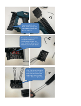
Step 2 For attachment to Spirax Sarco actuators
Usingthe2oM6panheadscrews,securelyattachthe'T'shapedslidingpinholdertothevalve
actuatorcouplingblock(Figure2).ApplyLoctitetotheslidingpinandscrewintohole'Y'(asshown)
on the sliding pin holder and tighten.
Usingthe2oM8x15hexheadscrewsand8mmspringwashers,attachthemountingplatetothe
backofthepositioner,utilisingholesNo.2inthebracket(Figure3).Takecarenottoover-tighten
thesescrewsandstripthethreads.
Step 3 For attachment to non-Spirax Sarco actuators
Usingthe2offM6panheadscrews,securelyattachthe'T'shapedslidingpinholdertothevalve
actuatorcouplingblock(Figure2).Dependingonthetravelofthevalveactuator,applyLoctiteto
slidingpinandscrewintothecorrectholeontheslidingpinholderandtighten.UseFigure2and
Table 1 to determine the correct hole to use.
Fig. 2
Close-up of
sliding pin holder
fitted to valve
coupling.
Fig. 3
Valve travel Hole to be used
8-15mm X
15-30mm Y
above30mm Z
Table 1
Usingthe2offM8x15hexheadscrewsand8mmspringwashers,attachthemountingplate
to the back of the positioner. The correct fixing hole may be determined by reference to Figure
3, Table 2 and Figure 4. Take care not to over-tighten these screws and strip the threads.
Z
X
Y
Valve
actuator
coupling
block
'T'shaped
sliding pin holder
1
3
4
2
Positioner
Mounting plate

3.568.5275.226
7
Fig. 5
Table 2
D Hole to be used
Upto125mm 1
125to150mm 2
150to175mm 3
above 175 mm 4
Fig. 4 Pillar/yoke spacing, showing 50 % travel.
Actuator
spindle
Actuatorpillar
or yoke
100%
50%
0%
D
Valve
position
indicator
Slide pin
Step 4 Temporarily apply adequate air pressure directly into the actuator so that the valve is
at50%oftravel(Figure5).
Step 5Engagetheslidepinintothepositionerlever(seeFigure5,notingthepositionofthe
spring,abovethepin)andlooselyxthepositionertotheactuator.Foryokeactuatorsusethesin-
gleelongatedscrewholewiththeM8x20screwandspringwasher,forpillarsusetheU-clamps.
Important:Slidepositionerverticallyupordowntheyoke/pillarssothepositionerleverishorizontal
at50%travel,andtheindicatoratLHSisaligned(Figure5).Securethetighteningscrews/nuts.

3.568.5275.226
8
Step 6Fittheangledprotectionplatetotherearofthepositionerusingthe2ocaptiveM3pan
headscrews.Accesstothesecaptivescrewsisfrominsidethepositioner.
Step 7 Adjusttheairsupplypressuretostroketheactuatorfrom0%to100%andensurethe
positioner lever rotates freely. Remove the temporary air supply from the actuator.
Step 8 Fitting a gauge block (optional)
ToaidcommissioningitisrecommendedtotagaugeblockandpressuregaugestoallEP5s.Please
note that gauges and gauge block can be supplied as spare parts if required.
FitgaugestotheblockbeforeattachingtheblocktotheEP5.Usethreadsealanttoensureairtight
connections.TheuppergaugedisplaystheoutputoftheI/Pconverter,andisnormally0-2barg.The
lowergaugedisplaysthepositioneroutputpressure,sothegaugerangewilldependontheactuator.
RemoveanyairttingsandblankingplugfromtheEP5,thenattachtheassembledblocktotheEP5
usingthe2osocketheadcapscrewssupplied.Ensurethesealing'O'ringsarecorrectlyttedto
sealthejointsbetweentheEP5bodyandthegaugeblock.Replacethettingsandblankingplug
into the corresponding ports on the gauge block.
3.3 Connecting up
3.3.1 Pneumatic connections (with or without a gauge block)
Warning:Airsupplymustbedry,oilanddustfreetoISO8573-1:class2:3:1.Acoalescinglter
regulatorsuchasaSpiraxSarcoMPC2willremoveoilanddirttomeetthisstandardifpro-
perlyttedandmaintained.Dirtyairsupplymaydamagetheproductandinvalidatewarranty.
The supply air pressure must not exceed the maximum allowable air pressure of the actuator.
Avoiduseoffer rouspipeworkaf tert heM PC2.Forbestper formanc e,settheairsupplypressure
toabout0.5bargabovethepressurerequiredtofullytraveltheactuator.
Chec kallco nnec tionsfo rleaks.Pleas en otehowevert hattheEP5blee dsairinnor maloper ation
atarateofapproximately0.7Nm³/hour at 6 bar supply pressure.
PneumaticconnectionsarelocatedattherighthandendofthepositionerandidentiedI, S
and Oasfollows:
I - NotusedonEP5,t¼" NPT plug.
S - Airsupply-1.4bargto6barg,dependinguponrequiredactuatorspringrange.
O - Outputsignaltotheactuator.
Connections are ¼"NPTfemale. Interconnectionbetweenpositioner andactuator shouldbeat
least6mmODtube.

3.568.5275.226
9
3.3.2 Electrical connections
CablingshouldbeinstalledinaccordancewithBS6739-InstrumentationinProcessControlSy-
stems: Installation design and practice or local equivalent.
TheEP5onlyrequiresa4-20mA(standard)or2-10Vdc(ifrequested)signal.Removethefront
coverandlocatetheterminalblockandearthterminalpost(Figure6).
Note:Ensureresistancefromearthposttolocalearth(e.g.pipework)islessthan1Ω.
ConnectiontotheunitisthroughthePg13.5cablegland(assupplied),whichwhenusedwithsuitable
cablewillensuretheIP54protectionrating.Appropriateconduitconnectionsmaybeusedinstead.
Connectconductors(0.5to2mm²)totheterminalblockandearthpost(3mm²)notingthepolarity
+/-showninFigure6.
InhazardousareasusemodelISP5withintrinsicprotection(typeEExiallCT6,T5,T4)ensuringthe
powersupplyfromadjoiningequipmentiscertiedinaccordancewithEN50.014andEN50.020
standards,inrespectofthelimitsofelectricfeaturesshownatapprovalstage.Refertoapproval
certicatesuppliedwitheachISP5product.
Fig. 6
Cable
gland
Terminal
block
-
+
Earth
terminal
post
I
S
O

3.568.5275.226
10
4. Commissioning
Once the positioner has been mounted and connected up, proceeed as follows.
Step 1 Set the valve action
Establishingthecorrectactionofthevalveisdoneby:
a. ConnectiontoeitherU1orU2nozzles(seeFigure7)and
b. Settingthesliderintheupperorlowerportionofthecrescentshapedsectorlever(Figure8).
U1 = Increase action = Withincreasingelectricalcontrolsignaltheairpressuretotheactuator
willincrease.
U2 = Decreaseaction = Withincreasingelectricalcontrolsignaltheairpressuretotheactuator
willdecrease.
To change the working nozzle connections (U1 or U2):
Disconnecttheairsupply.Loosentheretainingplateandrotateitclearofthetubeholder.Pull
the tube holder clear of its seat and re-insert the tube holder into the alternative seat location.
Lockinplacewithalternativeretainingplate(lockunusedretainingplatetopreventlossofplate).
Reconnect air supply.
Fig. 7
Connection
tonozzleU2
Connection
tonozzleU1

3.568.5275.226
11
To change the slider location:
RefertoFigure8todeterminethecorrectportion.Tochangethesliderslackenthescrewandslide
it into the correct portion of the arm.
*Thearrowshowsthestemmovementdirectionwhentheinputcontrolsignalincreases.
Fig. 8a Increase action and spring extend
Fig. 8b Increase action and spring retract
Fig. 8c Decrease action and spring extend
Fig. 8d Decrease action and spring retract
Upper
sector
Upper
sector
Lower
sector
Lower
sector
U1nozzle
*
U2nozzle
*
U2nozzle*
U1nozzle
*
I
O
S
I
O
S
I
O
S
I
O
S

3.568.5275.226
12
Step 2 Set sensitivity
Thepositionersensitivityisadjustedusingthesensitivityscrew(Xp%,seeFigure10).Itissetde-
pending on air supply pressure. Before the commissioning stage it is essential to set the sensitivity
withinaproportionalbandof(3%to6%).UseFigure10toadjustthesensitivityscrewbyrstlyfully
closingthescrew(clockwise),thenreopenthescrew:-
Supply pressure (S) 1.4 bar -
Screwopen
¾ of a turn
4.0bar -
Screwopen
¼ of a turn
6.0bar - Screwopen
of a turn
Note: AdjustmentoftheXp%screwcausesachangeofpositioner'zero'point,anditistherefore
importanttorepeatthezeroingandtravelsettingprocedures(Steps4and5)afteranychanges.
Toincreasepositionersensitivityclosetheadjustingscrew,todecreasesensitivityopenthescrew.
Do notopenthescrewbeyondthemechanicallock.
Fig. 9
Fig. 10
Xpcorrectvalue
Openingdegree
¾
½
¼
0
3
6
1.4 bar
4.0bar
6.0bar
(Xp%)
Supply pressure
Sensitivityscrew

3.568.5275.226
13
Step 3 Set damping
Thenal adjustmentofdampingscrew shouldbeperformed withplantin operation,inorder to
limit,ifnecessary,theactuationspeed.Duringthecommissioningsetthedampscrewushwith
the body see Figure 11.
Thereductionofairowratecapacitytotheactuatorwillslowdownthevalvemovementtolimitthe
eectofcyclinghunting.Closingthescrew(clockwise)increasesdamping,andviceversa.
Step 4 Set zero point
Check all air and electrical connections are in place. Check air supply pressure (S)iscorrect(see
Section3.3.2).Checkelectricalcontrolsignal(A)(seeSection3.3.3)isattheminimumrequired
(normally4mAor0V),buttheapplicationmayrequireadierentsetting.Itmayalsobeadvisable
toincreasetheminimumby0.5mAor0.25Vtoensurethevalveiscompletelyclosed.For3-port
valves(oriftheactionhasbeenreversedfor2-portvalves)ahigherelectricalsignalcorresponds
totheclosedvalveposition,itmaybebenecialtodecreasethemaximumelectricalcontrolsignal
to19.5mAor9.75V.Thiswillensurethatthevalveisrmlyseatedwhenthefullelectricalsignal
of20mAor10Visapplied.
Locatezeropointadjustmentscrew(seeFigure12)andreleasethelockingring.Adjustscrewuntil
thevalvestartstomoveandlocktheadjusterinplace.
Checkthezeropointbyreducingtheelectricalcontrolsignal(A)(seeSection3.3.3)tozero.Slowly
increasetheelectricalcontrolsignaltowardstheminimumlevelwhilstmonitoringvalvemovement.
Shouldmovementtakeplacebeforeoraftertheminimumcontrolsignalthenrepeatadjustment
untilmovementcoincideswithminimumcontrolsignal.
Fig. 11
Dampscrew
Fig. 12
Slider
Lockingring
Zero point
adjustmentscrew
Sector lever
Centrallockingscrew
Note:Positionersfittedwithagaugeblockhavethebenefitofanticipatingvalvemovementby
indicating increases of output air pressure.

3.568.5275.226
14
Step 5 Set travel
Increasetheelectricalcontrolsignaltotheuppervalue(normally20mAor10V,butthisdependson
theapplication)andnowcheckthetravelofthevalve.Ifrequired,slackenthecentrallockingscrew
(seeFigure12)andadjustthesliderupordowntheupperorlowerportionofthecrescentshaped
sectorlever.Movingthesliderawayfromthepivotwillreducethetravel,andviceversa.Normally,
exceptwith3-portvalves,thefullyopenpositionisachievedbeforethevalveplughitstheupper
mechanicalstopofthevalve/actuator.Avoidsettingsofthepositionerthatallowcontactwiththis
mechanicalstop.Varytheelectricalcontrolsignalaroundtheuppervaluetoverifythetravelsetting,
andifnecessaryrepeattheadjustmentoftheslideruntiltherequiredtraveloccursattheuppervalue.
Important:ZeroandtravelsettingsonEP5arenotindependentofeachother,sore-checkthezero
setting as described in Step 4. It may prove necessary to repeat Steps 4 and 5 several times until
acceptablezeroandtravelsettingsareachieved.Forneadjustmentofthetravel,thepotentiometer
showninFigure13canbeused.Thisshouldonlybeusedfornaladjustmentof+/-5%.
Whencomplete,lockbothzeroandtraveladjustments.
Split range operation
EP5maybesplitrangedtosequentiallyactuatetwovalvesfromonecontrolsignal
(Forexample:valve1setto4-12mAandvalve2setto12-20mA).Splitrangingisachieved
byadjustmentofthezeroandtravelsettingsrefertoSteps4and5.
Fig. 13
Traveladjustment
potentiometer

3.568.5275.226
15
5. Maintenance
5.1 Regular maintenance
1. Drainanybuild-upwithintheairsupplyltersetasimpuritiessuchasoil,wateranddirt
willcauseinconsistentoperation.
2. Ensureairsupplyisatthecorrectpressure(seeSection3.3.2andrefertoactuatorTI).
3. Make visual checks to ensure the valve is operating correctly.
5.2 Corrective maintenance
5.2.1 Removal and cleaning of sensitivity adjuster (see Figure 14):
- Loosenandremovelock.
- Notesettingthenremovesensitivityscrew.
- Washadjusterwithsolvent,checkingconditionoftheconeandensuring0.35mmside
hole is clear.
- Drywithcleancompressedairtoensurenoremainingcontaminants.
- Retthecleanedadjusterandunscrewit1turnfromitsstop.
- Retthelocktotouchtheadjustertopandsecurewithlock-nut.
- Set sensitivity see Step 2, Section 4, Commissioning.
- Resetzeroandspanifrequired.
Fig. 14

3.568.5275.226
16
5.2.3 Check damping grease:
- Ensuregapof1mmexistsbetweenfacesofdamper.Adjustifnecessary.
- Verifygreaseispresentbetweenfaces.
- Replacegreaseifnecessary(contactSpiraxSarcofordetails).
5.2.2 Removalandcleaningofcapillaryorice (see Figure 15):
- Loosenlockingplatescrew.
- Rotatelockingplatetoexposecapillaryorice.
- Usingsuppliedextractor/cleanerpulltheoricefromthebody.
- Cleanthesmalloriceandcrossdrillingusingonlythespecialcleaningwiresupplied.
- Reassembletheoriceensuringboth'O'ringsareinplaceandthelockplatecoverstheorice.
Fig. 16
Lockingplate
Capillary orifice
Dampingfaces
Capillary extractor /cleaner
Fig. 15
Extracting
thread
Cleaningwire
Extractor/cleaner
Capillary orifice
Spare'O'ring

3.568.5275.226
17
6. Spare parts
Available spares
Gaugeblock(withoutgauges) 1
Gauge0-2bar 2
Gauge0-4bar 3
Gauge0-7bar 4
Springs and tubes 5
Set of gaskets, diaphragms and orifice 6
Amplifyingrelayset 7
How to order spares and accessories
Always order spares by using the description in the column headed 'Available spares' and a
descriptionoftheproduct,togetherwiththeTAGnumber.
Example:1offGauge0-2barforaSpiraxSarcoEP5positioner,TAG907.
Product return procedure
Pleaseprovidethefollowinginformationwithanyequipmentbeingreturned:-
1. Yourname,Companyname,addressandtelephonenumber,ordernumberandinvoice
and return delivery address.
2. Descriptionofequipmentbeingreturned.
3. Descriptionofthefault.
4. Iftheequipmentisbeingreturnedunderwarranty,pleaseindicate:
i. Dateofpurchase
ii.Originalordernumber
Please return all items to:
ReturnsInvestigationsDepartment
Runnings Road,
KingsditchTradingEstate
Cheltenham
Glos,GL519NX
UnitedKingdom
Alternatively, please return any items to your local Spirax Sarco branch.
Pleaseensureallitemsaresuitablypackedfortransit(preferablyintheoriginalcartons).
Fig. 17
1
2
3 or 4
76
5
TAGnumber

3.568.5275.226
18
7.Faultnding
Output pressure too low or zero
Cause Remedy
a. No control signal a.RestoremAsignal
b.Lowairsupplypressure b.Verifyactuatorairpressurerequirement
c.Cloggedordirtysensitivityadjuster c.CleanadjusterseeSection5.2.1
d. Clogged or dirty capillary orifice d. Clean orifice see Section 5.2.2
e. Incorrect set-up e. Recalibrate see Section 4, Steps 1 to 5
f.Damagedpneumaticactuatororpiping f.Verifyreplaceasnecessary
g. Port I not blanked or leaking g. Insert ¼" NPT blank in port I
Output pressure too high
Cause Remedy
a.Sensitivityadjusteropentoofar a. Recalibrate see Section 4, Step 2
Actuator movement too slow
Cause Remedy
a.Lowairsupplycapacity a.Checksupplycapacityandpipesizes
b.Dampingscrewclosedtoofarorclogged b. Recalibrate see Section 4, Step 3
Actuator failing to close
Cause Remedy
a.Outputpressuretoolow a. Refer to previous fault
b.Incorrectzeropoint b. Recalibrate see Section 4, Step 4
c.Dampingscrewclosedorclogged c.CleanscrewandrecalibrateseeSection 4, Step 3
d.Valve / actuatorcouplingincorrect d.Reset(refertovalve/actuatorIMIs)
e.Actuatortoosmall e. Fit correct actuator
Actuator failing to fully open valve
Cause Remedy
a.Outputpressuretoolow a. Refer to previous fault
b.Incorrecttraveladjustment b. Recalibrate see Section 4, Step 5
c.Dampingscrewclosedorclogged c.Clean screw andrecalibrateseeSection 4,Step 3
d.Valve /actuatorcouplingincorrect d.Reset(refertovalve/actuatorIMIs)
e.Actuatortoosmall e. Fit correct actuator
Hunting
Cause Remedy
a.Incorrectcontrollersetup(P, I, and D) a.Verify and adjust accordingto process requirement
b. Sensitivity orifice closed too far b.Adjustbyopeningsensitivityscrew
see Section 4, Step 2
c.Excessivevalvefriction c.VerifyandmaintainasvalveIMI
d.Controlvalveover-sizing d. Verify operating conditions againstvalve capacity.
Note:Theeffectsofhuntingcausedbyvalveover-sizingorunstableprocessconditionscanbe
reducedbyadjustmentofdampingscrewseeSection4,Step3.

3.568.5275.226
19

3.568.5275.226
20
/